![]()
Page History
This page provides information on the V-Ray Spot Light.
Overview
...
The V-Ray Spot Light is a V-Ray specific light source that can be used to create a physically accurate light that directs a narrow beam of light with falloff.
UI Paths:
||obj Network|| > V-Ray > V-Ray Spot Light
...
| Section | |||||||||||||||||
|---|---|---|---|---|---|---|---|---|---|---|---|---|---|---|---|---|---|
|

...
...
| Anchor | ||||
|---|---|---|---|---|
|
Example: Cone Angle
...
This example demonstrates how the light changes with the change of the Cone Angle. The Penumbra Angle is set to 20 for all renders, only the degrees of the Cone Angle change. Notice how lower degrees result in sharp shadows and focused light, while higher degrees make the light diffused and the shadows blurrier.
| Section | ||||||||||||||||||||||||||||||||||||||||||||||||||||
|---|---|---|---|---|---|---|---|---|---|---|---|---|---|---|---|---|---|---|---|---|---|---|---|---|---|---|---|---|---|---|---|---|---|---|---|---|---|---|---|---|---|---|---|---|---|---|---|---|---|---|---|---|
|


...
Anchor penumbra penumbra
Example: Penumbra Angle
...
This example demonstrates the behavior of the light when changing the Penumbra Angle. The Cone Angle is set to 20 for all renders.
| Section | |||||||||||||||||||||||||||||||||||||||||||||||||||||
|---|---|---|---|---|---|---|---|---|---|---|---|---|---|---|---|---|---|---|---|---|---|---|---|---|---|---|---|---|---|---|---|---|---|---|---|---|---|---|---|---|---|---|---|---|---|---|---|---|---|---|---|---|---|
|


...
| Anchor | ||||
|---|---|---|---|---|
|
| Multiexcerpt | ||||||
|---|---|---|---|---|---|---|
| ||||||
|
...
|


...
|


...
|
...
|


...
|


...
...
|
...
|


...
...
Shadows
...
| Section | |||||||||||||||||
|---|---|---|---|---|---|---|---|---|---|---|---|---|---|---|---|---|---|
|

...
Textures
...
| Section | |||||||||||||||||
|---|---|---|---|---|---|---|---|---|---|---|---|---|---|---|---|---|---|
|

...
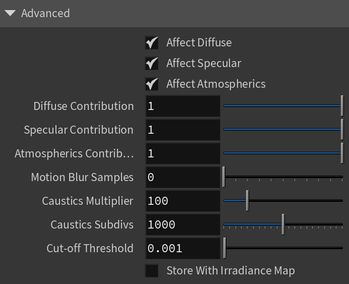
Advanced
...
| Section | |||||||||||||||||
|---|---|---|---|---|---|---|---|---|---|---|---|---|---|---|---|---|---|
|