Versions Compared

Key

  • This line was added.
  • This line was removed.
  • Formatting was changed.

...

Section
Column
width60%

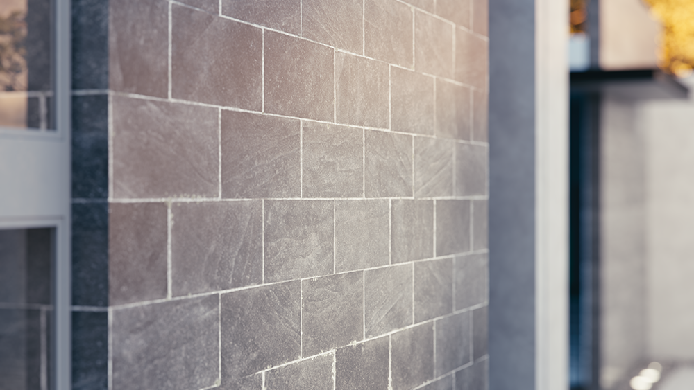
Displacement mapping is a technique for adding detail to geometric objects without having to model it first. The concept is very similar to bump mapping. However, bump mapping is a shading effect that only changes the appearance of a surface, while displacement Displacement mapping actually modifies the surface.

The image slider on the right shows the effect of the Displacement mapping.

Column
width5%


Column
width35%
Before after
afterLabelenabled
beforeLabeldisabled
Panel
borderStylenone
Panel
borderStylenone

...

Section
ui
Fancy Bullets
typecircle
  • Create a Displacement geometry in the Asset Editor from the Geometry drop-down menu or from Create Asset > Geometries > Displacement and assign a texture to the Map slot.
    Currently, the displacement Displacement geometry is not assigned to any object in the Revit model and it is not visible during rendering.
  • In the Appearance Manager, navigate to the material that needs displacementDisplacement.
  • From the V-Ray drop-down menu next to it,  select select Displacement. A grey dot indicates that the Displacement is assigned to that material. All objects that have the material assigned to them also acquire the Displacement.
  • A drag-and-drop option is also available for assigning Displacement to any material in the Appearance Manager.
  • Materials with assigned Displacement can be filtered from the Filter icon (Image Added), which is located in the search window.
text-box
UI Text Box
colorlight-blue
iconinfo

Image Added - Asset Editor - Enables/disables the Displacement, applied for all the materials, globally.

Image Added - Appearance Manager - Enables/disables the Displacement, applied on the selected material

typetip

Displacement assigned to a material can be disabled from the Displacement (Image Removed) icon in the Appearance Manager when the material is selected.

Section
Column
width15%


Column
width70%

Image Modified

Column
width15%


...

Anchor
water
water

...

Example: Level Height 


The Level Height parameter is absolute in world units. For this example, Amount is set to 5.0 and Shift is set to 0.0. Note that when Level Height reaches Amount + Shift, all geometry is clipped.

...

Anchor
edgeLength
edgeLength
 

...

Example: Edge Length


This example shows the effects of increasing the Edge Length parameter. In this example View Dependent is enabled, so Edge Length is expressed in pixels. In the examples, the closeup view is a blow-up rather than a zoomed view. This means that Edge Length in the closeup view refers to pixels in the original image, not the blow-up rendering. Click the images for a larger view.

...

Anchor
Keep
Keep

...

Example: Keep Continuity


The Keep Continuity option is useful for objects with disjoint normals on neighboring triangles, usually because of different smoothing groups. In the middle image below you can see the edge splits produced by disjoint normals. Using the Keep Continuity option avoids this problem. This option also helps to produce a smoother result across material ID boundaries for objects that have been assigned MultiSubObject materials.

...