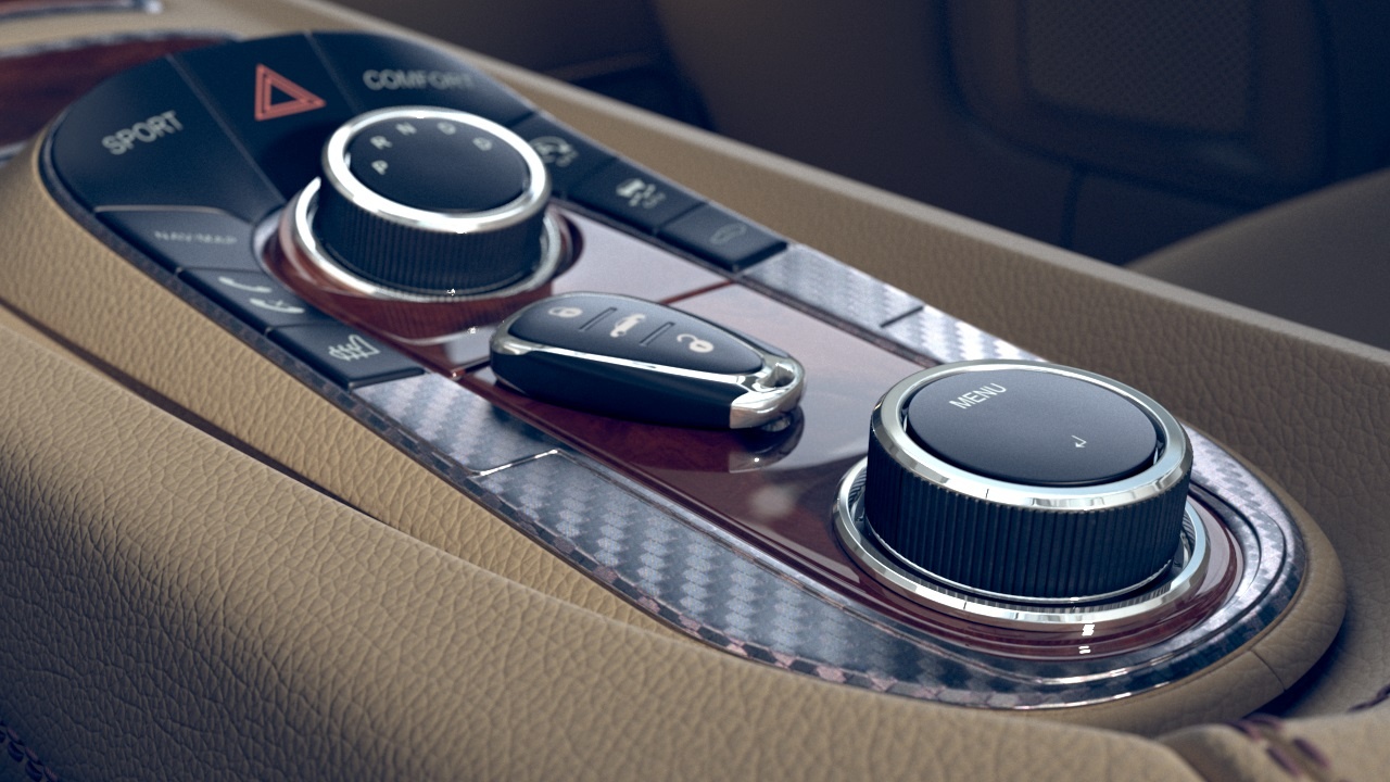
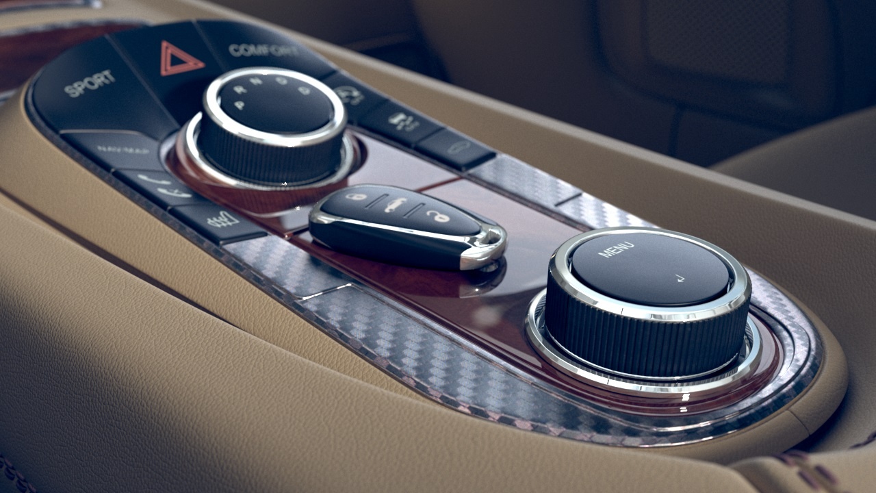
The Corona Scanned Material allows you to use Chaos Scans with Corona.
There are some materials that are impossible to recreate with any number of parameters and maps in a generalized material, as they have a unique way of responding to light. This is where Chaos Scans comes in. Each material in the library is meticulously scanned to capture how it interacts with light so that you can drag-and-drop it into your scene for 100% accuracy in both look and scale.
Column
width
5%
Column
width
45%
...
Section
Column
width
50%
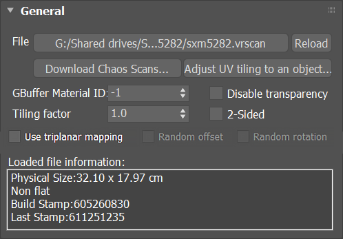
File – The file name with the data for the scanned material; usually has a .vrscan extension.
Reload – Refreshes the .vrscan file loaded in the material.
Download Chaos Scans... – This button redirects you to the Chaos Scans download web page.
UI Text Box
type
note
The material preview remains empty until the scanned material is loaded.
UI Text Box
type
info
Additionally, a scanned material file can be loaded by dragging and dropping it in the Load from file... button.
UI Text Box
type
tip
All scanned materials are listed in the Asset Tracking window, like any other asset in the scene.
2-Sided – Forces the back-facing polygons to be shaded in the same way as the front-facing ones. When disabled, the back-facing polygons appear black. This can be useful for objects like curtains. Note that this option is always considered enabled when rendering transparent materials.
Disable transparency – Disables transparency for materials that store such information. This can be useful for speeding up the rendering, especially when the transparency produces little or no effect.
Information – Displays some useful information contained in the .vrscan file, such as the actual material sample size.
Use triplanar mapping – Enables the triplanar mapping for the scanned material.
Random offset – Enables the random offset for the scanned material.
Random rotation – Enables the random rotation for the scanned material.
UI Text Box
type
note
The Random offset and rotation parameters are only available when the Triplanar mapping is enabled; otherwise, they remain inactive.
Column
width
5%
Column
width
45%
Image RemovedImage Added
Appearance
...
Section
Column
width
50%
Filter Color – A color multiplier for the material sample that can be used to tint the material. (It affects the color of the reflections as well. Acts as a post effect.) See the Filter Color example below.
Paint Color – Changes the color of the material without losing the texture or changing the reflection color. For example, it can be used to change the color of wood or leather without losing the material texture.
Gamma – Controls the color curve correction of the material.
Saturation – Controls the saturation of the material (including Filter Color and Paint Color if used) as a post-effect. See the Saturation example below.
Column
width
5%
Column
width
45%
...
Section
Column
width
50%
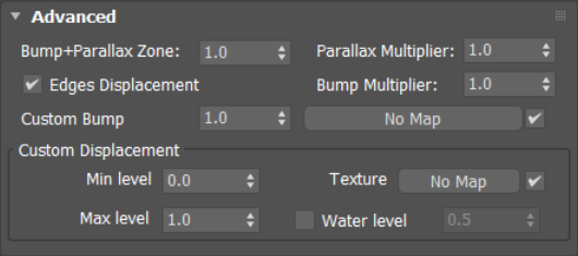
Bump + Parallax Zone – Determines the point where additional bump and parallax no longer exist and only natural height effects remain. This option is especially useful for shallow angles of view to the material, where it might appear flat or less detailed. A value of 0 adds no additional bump and parallax. A value of 1 adds additional bump and parallax equally regardless of the view angle. All scanned materials by default have the most suitable value loaded for this parameter to achieve the most realistic look. If you need full control over the bump and the parallax, set the value to 1 and work with the Parallax and Bump Multipliers.
Parallax Multiplier – Adjusts additional parallax and edge displacement strength.
Bump Multiplier – Adjusts the additional bump.
Edges Displacement – Uses a special technique that makes the edges of the geometry appear slightly jagged inwards. This option is useful when rendering close-ups of materials with bumps. It is faster than actual displacement and helps to achieve better realism.
Custom Bump – Allows loading a specific texture map for the bump.
Custom Displacement
Min level – Displacement distance applied to areas with black (0.0) texture. Measure in world space units.
Max level – The strength of the displacement effect. It is the world-space displacement distance applied to areas with white (1.0) texture.
Texture – Allows loading a specific texture map for displacement.
Water level – Displacement cutoff threshold. Any micro triangles with displacement texture value below this level are removed.
Column
width
5%
Column
width
45%
Image RemovedImage Added
Clear Coat
...
Section
Column
width
50%
Enable – Enables the tracing of a clear coat layer for the material.
Strength – Specifies the strength of the coat reflections.
IOR – Determines the IOR of the coat layer, and from that controls the strength of the reflections. A value of 1.0 does not produce any reflections and disables the coat layer. Higher values produce stronger clear coat reflections. The .vrscan files typically contain the correct value for this parameter and it is set automatically when the file is loaded.
Bump multiplier – The coat layer has a built-in bump map stored in the material sample file. This allows control over the strength of that bump.
Coloring – Colors the coat reflections.
Glossiness – Controls the sharpness of reflection. A value of 1.0 means perfect glass-like reflection; lower values produce blurry or glossy reflections.
Glossiness variation – Controls the effect of glossiness growth under shallow observation angles. This parameter represents a real physical effect proper to materials like brushed metals, plastics, etc. The parameter range is 0-1. Higher values produce faster transition of the glossiness to 1 when the observation angle goes to zero.