Versions Compared

Key

  • This line was added.
  • This line was removed.
  • Formatting was changed.

This page provides a tutorial on creating a lava simulation with Phoenix FD in 3ds Max.

Overview

...

UI Text Box
sizemedium
typeinfo

This is an Advanced Level tutorial. The workflow for setting up the shot, and the Phoenix FD settings involved in the simulation are explained in detail. However, creating a production quality shot of a similar nature may require some tweaks to the lighting, materials and/or the Phoenix FD simulation.

Section
Column
width40%

Requires Phoenix FD 3.13 Release build or later and V-Ray Next Hotfix 1 Official Release for 3ds Max 2015+. If you notice a major difference between the results shown here and the behavior of your setup, please send an email to support@chaosgroup.com

The instructions on this page guide you through the process of using Phoenix FD's Variable Viscosity capabilities in order to simulate molten lava or metal cooling and hardening over a period of time.

The Download button below provides you with an archive containing the scene file.


UI Button
sizelarge
icondownload
titleDownload Project Files
urlhttps://drive.google.com/uc?export=download&id=1yPrxYGiLRBjVBwr9Mth4ngmxoJ-CJmXb

Column
width60%

Videoautoplayloop
0lava_finalRender.mp4
1100%
2100%
3true
4false
5true

Units Setup

...


Section
Column
width40%

Scale is crucial for the behavior of any simulation. The real-world size of the Simulator in units is important for the simulation dynamics. Large-scale simulations appear to move more slowly, while mid-to-small scale simulations have lots of vigorous movement. When you create your Simulator, you must check the Grid rollout where the real-world extents of the Simulator are shown. If the size of the Simulator in the scene cannot be changed, you can cheat the solver into working as if the scale is larger or smaller by changing the Scene Scale option in the Grid roll-out.

The Phoenix FD solver is not affected by how you choose to view the Display Unit Scale - it is just a matter of convenience.

Go to Customize -> Units Setup and set Display Unit Scale to Metric Centimeters.

Also, set the System Units such that 1 Unit equals 1 Centimeter.

Column
width60%


Scene Layout

...


Section
Column
width40%

The final scene consists of the following elements:

  1. A Standard Primitives → Box used as the source geometry for the liquid. An animated Noise modifier is applied to the geometry to break up the emission.
  2. A set of rocks provided with the rocks.abc file.
  3. Phoenix FD Liquid Source with the Box in its Emitter Nodes list. The Source is in Surface Force mode and Noise is enabled for extra randomization.
  4. Phoenix FD Liquid Simulator with some tweaks in the Grid, Dynamics, and Rendering roll-outs.
  5. Phoenix FD Mapper used to tweak the Viscosity of the liquid during the simulation.
  6. V-Ray Physical camera with minor tweaks for final rendering.
  7. A V-Ray Dome Light using a custom HDRI.
  8. V-Ray Plane used as an infinite ground surface.

Column
width60%


Scene Setup

...


Section
Column
width40%

Set the Time Configuration → Animation Length to 150 so that the Time Slider goes from 0 to 150.

Column
width60%

...

Section
Column
width40%

To the right is a Viewport Preview showing the result of the simulation so far.

The difference after modifying the Viscosity with a texture is not immediately obvious but once the Cell Size is reduced for the final simulation, individual chunks of lava will start forming based on the different viscosity values.

Column
width60%

Videoautoplayloop
0009_addLiqSrc_ViscosityTexture.mp4
1100%
2100%
3true
4false
5true


Solidifying with a Phoenix FD Mapper

...


Section
Column
width40%
UI Text Box
sizemedium
typeinfo

In this section of the tutorial, we look into the process of using the Phoenix FD Mapper to gradually increase the viscosity of the lava over time. Real-world lava solidifies as it cools down - we want to replicate this behavior.

Create a Helpers → Phoenix FD → Mapper. The Phoenix FD Mapper can directly affect the components of the simulation. For instance, it can be used to overwrite the Viscosity values for certain cells of the Simulator.

Disable the Initializer option - if enabled, the Mapper will only work on the first frame of the simulation. When disabled, the Mapper is always active.

Set the Channel to affect to Visocsity.

Set Buildup Time to 0 so the Mapper will instantly set the cells of the Phoenix FD Simulator to the values of the Map texture for each frame of the simulation.

Finally, plug an Output texture to the Map slot of the Mapper. When you start a simulation, the Mapper will look at this texture to determine what values to apply to the cells of the Simulator.

Column
width60%

...

Section
Column
width40%

To the right is a low-quality render of the liquid mesh with a Phoenix FD Grid Texture reading the RGB Grid Channel applied to a V-Ray Material's Diffuse slot.

Column
width60%

Videoautoplayloop
0015_liqSrc_RGBTexture.mp4
1100%
2100%
3true
4false
5true


Camera & Light

...


Section
Column
width40%

Add a Command Panel → Cameras → V-Ray → VRayPhysicalCamera.

The exact position of the Camera is XYZ: [ 2, 318, 108 ].

The exact position of the Camera Target is XYZ: [ 16, 11, 44 ].

The Aperture → F-Number is set to 0.8.

The Aperture → Shutter Speed is set to 1000.

Both Depth of Field and Motion Blur are Enabled.

Color & Exposure → White Balance is set to D50.

Bokeh Effects → Blades is Enabled, with a value of 7. Rotation is set to 15, with a Center Bias of 1.

UI Text Box
sizemedium
typeinfo

 The V-Ray Settings → Rendering Output Width / Height is set to 800 / 450 for the example renders below.

Column
width60%

...

Section
Column
width40%

Add a V-Ray Infinite Plane by going to Geometry → Standard Primitives → VRayPlane.

To the right is a rendered image of the current setup plus the basic materials we create in the next section.

Column
width60%

Materials for the Rocks and Ground

...


Section
Column
width40%

Assign a V-Ray Material to the V-Ray Plane and rename it to mtl_ground.

Set the Diffuse to [ 2, 2, 2 ]

Set Reflect to [ 21, 21, 21 ]

Set Reflection Glossiness to 0.65.

Column
width60%

...

Section
Column
width40%

Here's a rendered image of the Rocks geometry with mtl_rocks applied.

Column
width60%


Material for the Solid Lava

...


Section
Column
width40%

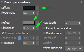
For the solid lava (the one with high Viscosity), assign a V-Ray Material to the Phoenix FD Simulator and rename it to solidLava. This material is the base for the final Complex Lava material we create in the next section.

Set the Diffuse to [ 1, 2, 3 ].

Set Reflect to [ 55, 55, 55 ].

Set Reflection Glossiness to 0.72.

Reduce the Bump to 15 under the Maps roll-out of the V-Ray material.

Column
width60%

...

Section
Column
width40%

Here's a rendered image of the Lava with the solidLava material applied to the Simulator.

Column
width60%


Material for the Liquid Lava

...


Section
Column
width40%

The material for the liquid lava consists of a regular V-Ray Material (coldLiquidLava) and a V-Ray Light Material (hotLiquidLava) blended together based on the output of a Phoenix FD Grid Texture reading the simulation's RGB Channel.

The hotLiquidLava Light Material is the core of the lava shader - the emitted light's color is based on the RGB Channel read through a Grid Texture.

The coldLiquidLava V-Ray Material is added into the mix for additional variation. Even very hot lava flows in real life has chunks of rocks that do not emit light. Having only a single Light Material would look unrealistic.

The Blend input of the liquidLava Blend Material is driven by the same RGB Channel - a Color Correct and Output nodes are used in-between to de-saturate and increase the contrast of the RGB Channel values.

Column
width60%

...

Section
Column
width40%

Plug the incOutputRGB Output texture into the Blend 1 slot of the liquidLava Blend Material.

To the right is a rendered image of the current setup.

Column
width60%


Complete Lava Shader

...


Section
Column
width40%

The final material for the lava consists of the coldSolidLava and liquidLava materials we prepared in the previous two sections of this tutorial.

A V-Ray Blend Material is used at the final wrapper. The Blend Material is driven by a Phoenix FD Grid Texture reading the Viscosity Grid Channel. Recall that the Viscosity in the simulation increases as the simulation progresses in time. Thus, higher viscosity values should correspond to solid lava with the coldSolidLava material applied.

The purpose of the Output node is to invert the values coming in from the Grid Texture. Note that the Coat 1 input of the Blend material is the liquidLava material. The Coat 1 is applied where the Blend texture is white. Therefore, if the Grid Texture output is not inverted, the high-viscosity areas of the simulation will receive the liquidLava material which would be incorrect.

Column
width60%

...

Section
Column
width40%

To the right is a rendered image of the final Lava material.

Column
width60%


Mesh Smoothing for the Lava Mesh

...


Section
Column
width40%


Optionally, you may choose to enable some Simulator → Rendering → Mesh Smoothing options if your lava simulation looks too sharp / jagged.

The settings for the smoothed image to the right are Simulator → Rendering → Use Liquid Particles enabled, and a Smoothness of 5.

Column
width60%
Image slider
Panel

Lava No Smoothing

Panel

Lava With Smoothing


V-Ray Frame Buffer

...


Section
Column
width40%

For the final image, some corrections are made in the V-Ray Frame Buffer.

Bloom/Glare Effect is enabled from the Lens Effects panel. The Size is set to 22, with a Bloom of 0.11.

Exposure is enabled from the Corrections panel and reduced to -1 to counter the brightening effect of the Bloom effect.

White Balance is also enabled and Temperature set to 8000 to pull the image away from the blue overall tint created by the Bloom effect.

Column
width60%

...