Versions Compared

Key

  • This line was added.
  • This line was removed.
  • Formatting was changed.

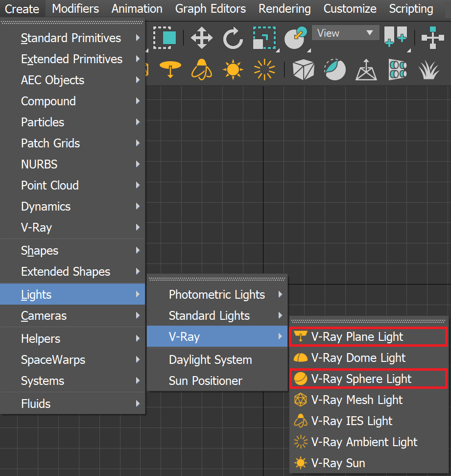
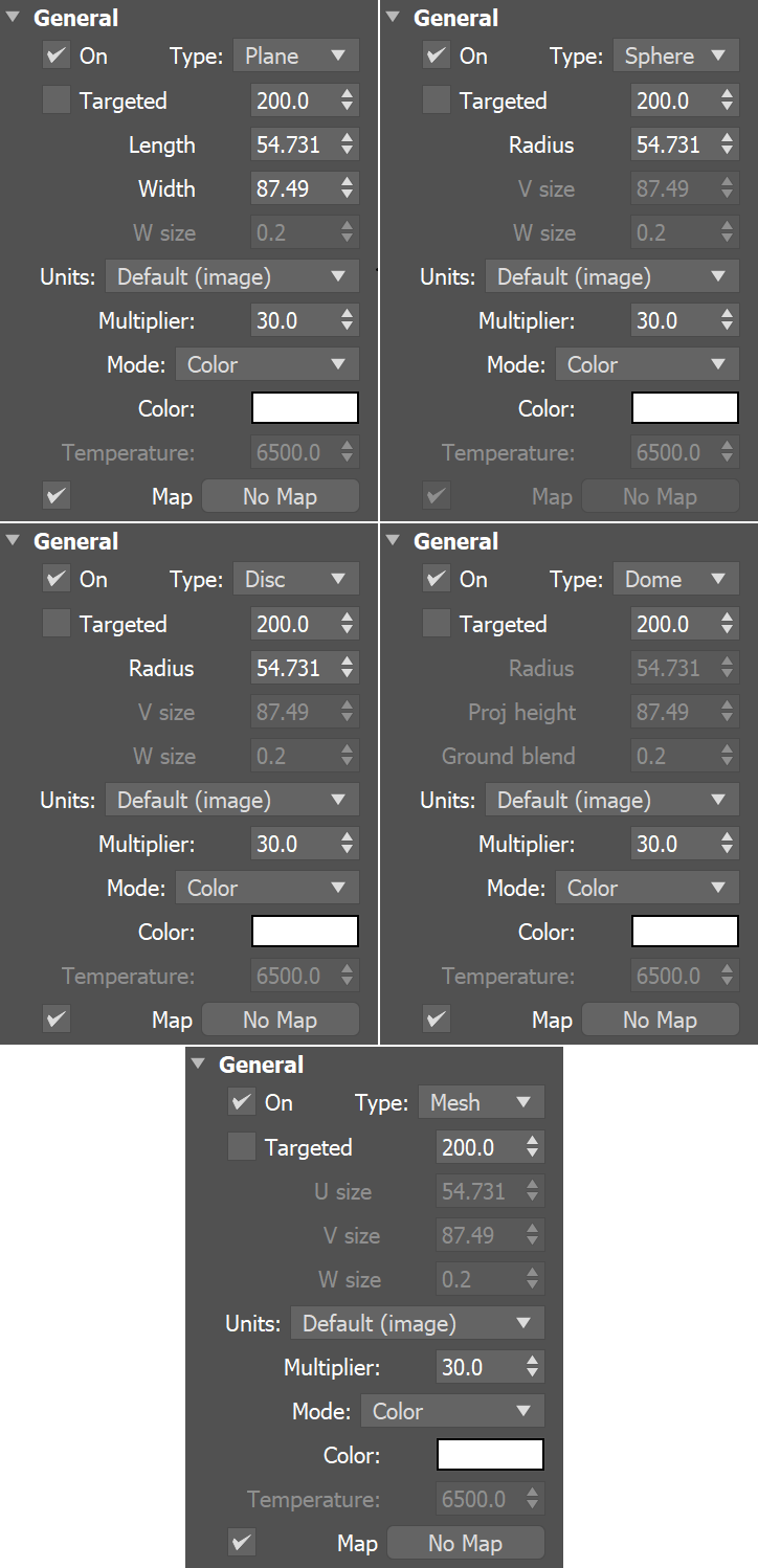
The Plane, Disc, and Sphere are each a type of VRayLight with similar options.


Overview

...

Plane, Disc, and Sphere lights are types of VRayLight objects. These are good general-purpose V-Ray lights for lighting scenes to simulate real-world light sources like lamps and ceiling lights.


UI Expand
expandedtrue
titleUI Path: ||Create menu|| > Lights > V-Ray...
Section
Column
width40%

||V-Ray Toolbar|| > V-Ray Plane/Sphere/Disc Light button > Click and drag in a viewport


Column
width2%


Column
width55%57%

||V-Ray menu|| > Create > Lights > V-Ray Plane/Sphere Light


Section
Column
width40%

||Create menu|| > Lights > V-Ray > V-Ray Plane/Sphere Light > Click and drag in a viewport

Column
width2%


Column
width57%55%

||Command panel|| > Create tab > Lights > Choose V-Ray from dropdown > VRayLight > Click and drag in a viewport 

...

UI Text Box
typeinfo

For disc and plane lights, press the Alt key while creating the light to point it in a backward direction of the plane.


Sample Uses

...

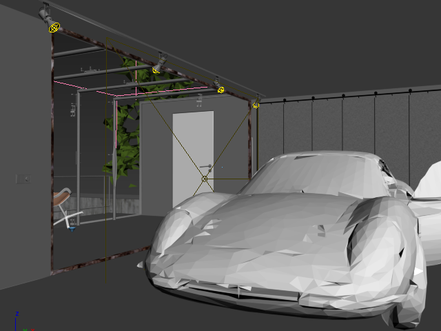
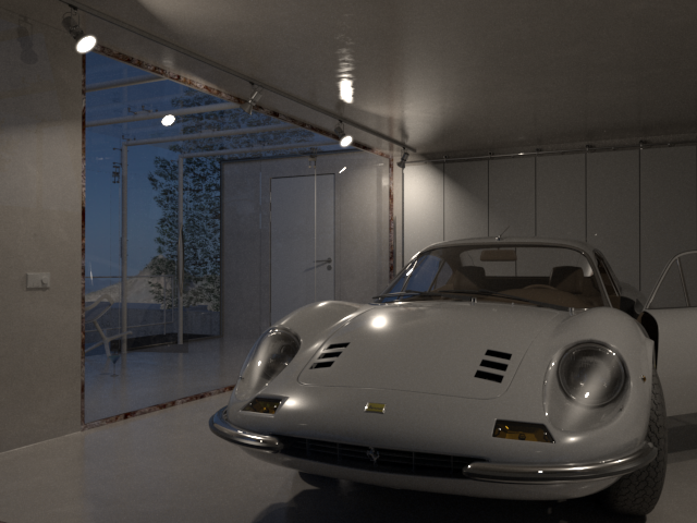
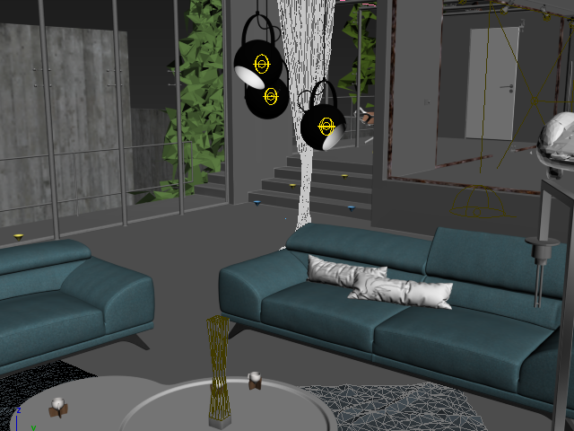
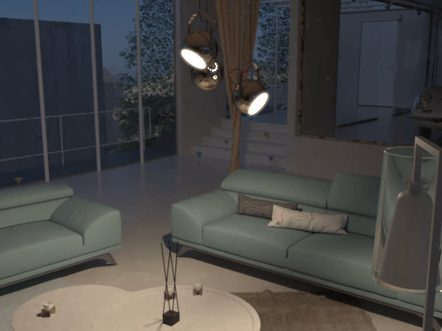
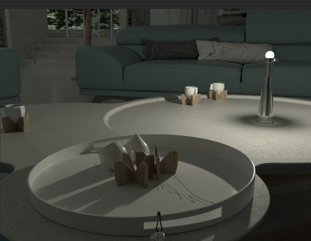
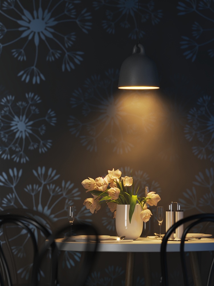
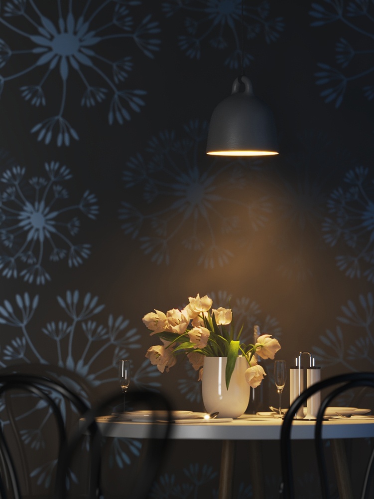
By default, V-Ray renders the light source if it is seen in the camera, as shown in the examples below. To render without seeing the light source, enable the light's lnvisible option.

Note: When a PlaneDisc, or Sphere light is visible in the rendering, aliasing at the edges of the light source can occur. Lens Effects such as the Bloom Effect (as used in the example images below) and Glare Effect are one way to hide the aliasing, while another is the use of a VRaySoftBox map. For information on the cause of the aliasing and solutions for it, see Notes below.


Section
Column
width10%


Column
width40%


Plane
 lights in viewport


Column
width40%


Plane lights rendering (with slight Bloom Effect) 


Column
width10%


Section
 
Column
width10%


Column
width40%


Disc
lights in viewport


Column
width40%


Disc lights rendering (with slight Bloom Effect)


Column
width10%


Section
 
Column
width10%


Column
width40%


Sphere
lights as light bulbs in hanging fixture


Column
width40%


Sphere lights rendering (with slight Bloom Effect)


Column
width10%


Parameters - General Rollout

...

Section
Column
width60%

On – Turns the VRayLight on and off.

Type – Specifies the shape and function of the light:

Anchor
Plane
Plane
Plane – The VRayLight takes the shape of a planar rectangle.
Sphere
 – The VRayLight has the shape of a sphere.
Dome – The VRayLight emanates from a spherical or hemispherical dome around the scene extents. See the Dome Light page.
Mesh
 – Allows the usage of any mesh object as the shape of the light. See the Mesh Light page.
Disc – The VRayLight takes the shape of a planar disc.

Targeted – When enabled, a separate target object is attached to the light source. This target object can be moved separately from the light source, making it easier to point the light within the scene. The value specifies the distance from the light source to the target. While any type of VRayLight can have a target, the target is truly useful only with Plane and Disc lights. This option can be changed only in the Modify tab.

Length – The length of a Plane light source, measured in scene units.

Width – The width of the Plane light source, measured in scene units.

UI Text Box
sizemedium
typetip

Using the length, width or V size parameters is the recommended method for controlling the light's size. Avoid scaling the light. Uniform scaling can be used when the scene needs to be scaled up or down, but non-uniform scaling produces skewed or elliptical shapes, which may produce incorrect results.

Radius – The radius of the Sphere or Disc light source, measured in scene units.

Note: The size of the light source sometimes affects the light's intensity, shadows, and light diffusion depending on what is selected for the Units parameter. For more information, see Example: Light Units, Light Size and Shadow Crispness.

Units – Specifies the light units. Using correct units is essential when you work with the VRayPhysicalCamera. The light automatically takes the scene's unit scale into consideration to produce the correct result for the scale you are working with. The possible values are:

Default (image) – The color and multiplier directly determine the visible color of the light without any conversion. The light surface appears with the given color in the final image when seen directly by the camera (assuming there is no color mapping involved).
Luminous power (lm) – Total emitted visible light power measured in lumens. When this setting is used, the intensity of the light does not depend on its size. A typical 100W incandescent light bulb emits about 1500 lms of light.
Luminance (lm/m²/sr)
 – Visible light surface power measured in lumens per square meter per steradian. When this setting is used, the intensity of the light depends on its size. 
Radiant power (W)
 – Total emitted visible light power measured in watts. When using this setting, the intensity of the light does not depend on its size. Keep in mind that this is not the same as the electric power consumed by a light bulb for example. A typical 100W light bulb only emits between 2 and 3 watts as visible light. 
Radiance (W/m²/sr)
 – Visible light surface power measured in watts per square meter per steradian. When this setting is used, the intensity of the light depends on its size.

Multiplier – Multiplier for the light color, and also the light intensity for some Units settings.

Mode – Specifies the mode in which the color of the light is determined:

Color – Тhe Color swatch specifies the color of the light rays and of the light source itself when visible in renderings. For Units settings other than Default (image), this color is normalized so that only the color hue is used. 
Temperature
 – Тhe color of both light rays and the light source itself is specified by the Temperature value expressed in Kelvin.

Map – Enables the use of a texture for the light surface when a Plane or Disc light type is used. The button under this option selects the map to use. The texture intensity is also affected by the Multiplier value. The light uses the texture's alpha as opacity map.

 
Column
width5%


Column
width35%


Anchor
normalizeIntensity
normalizeIntensity

...

The following images show how the size of a Sphere light source affects shadows. Larger light sources produce blurrier shadows, while smaller light sources produce sharper shadows:

...


Section
 
Column
width25%


Column
width50%
Image slider
Panel
borderStylenone


 Radius = 0.5Units set to Luminous power (lm)

Panel
borderStylenone


 Radius = 1.0Units set to Luminous power (lm)

Panel
borderStylenone


 Radius = 2.0Units set to Luminous power (lm)

Column
width25%


...

Example: Light Size and Intensity

...

The same is not true for other Units settings. With the Default (image), Luminance (lm/m²/sr) and Radiance (W/m²/sr) settings, the light's intensity is directly affected by the size of the light source. 


Section
Column
width25%


Column
width50%
Image slider
Panel
borderStylenone


 Radius = 0.5Units = Default (image)

Panel
borderStylenone


 Radius = 1.0; Units = Default (image)

Panel
borderStylenone


 Radius = 2.0; Units = Default (image)

Column
width25%


...


...


Parameters -   Rectangle/Disc Light Rollout

...

Section
Column
width60%

This rollout is only available when the Type the Type is set to to Plane or Disc.

Directional – By default, the light from the Plane or Disc light is spread out equally in all directions on the side in which the light points. As this parameter is increased toward a value of 1.0, the spread narrows, making the light more directional. A value of 0 (default) makes the light shine in all directions around the light source. A value of 0.5 pushes the light cone to a 45-degree angle, and a value of 1.0 (maximum) makes a 90-degree light cone. For more information, see the Directional Spread example below.

Directional strength – Controls the blend between diffuse distribution and directional distribution. For example, setting the directional strength to 0.9 makes the light emit a portion of its energy (i.e. 10 percent) with diffuse distribution. This makes the light visible from the side in the reflections.

Preview – Allows the light's spread angle to be seen Preview – Allows the light's spread angle to be seen as a wireframe in the viewport, as it is set by the light's Directional parameter.

Always – The preview is always displayed. 
Selected – The preview is displayed only when the light is selected. 
Never – The preview is never displayed.

Preview texmap – If a texture is used to drive the light, enabling this shows the texture in the viewport. This option is grayed out if your 3ds Max viewport is configured to use Nitrous viewport driver. To enable, switch to the direct3D viewport.

 
Column
width5%


Column
width35%

Image Removed

...

Max2024_VRay6.2_Plane_RectangleImage Added


Anchor
DirectionalExample
DirectionalExample
 

...


Example: Directional Spread

...


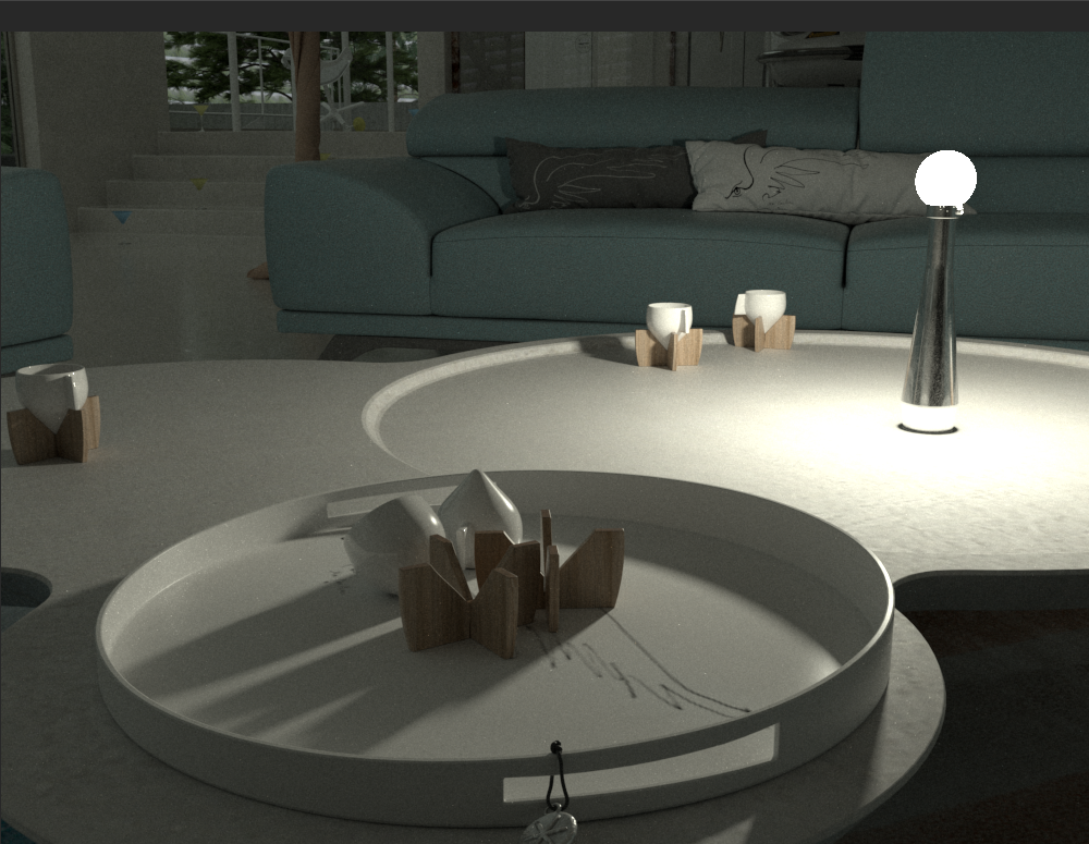
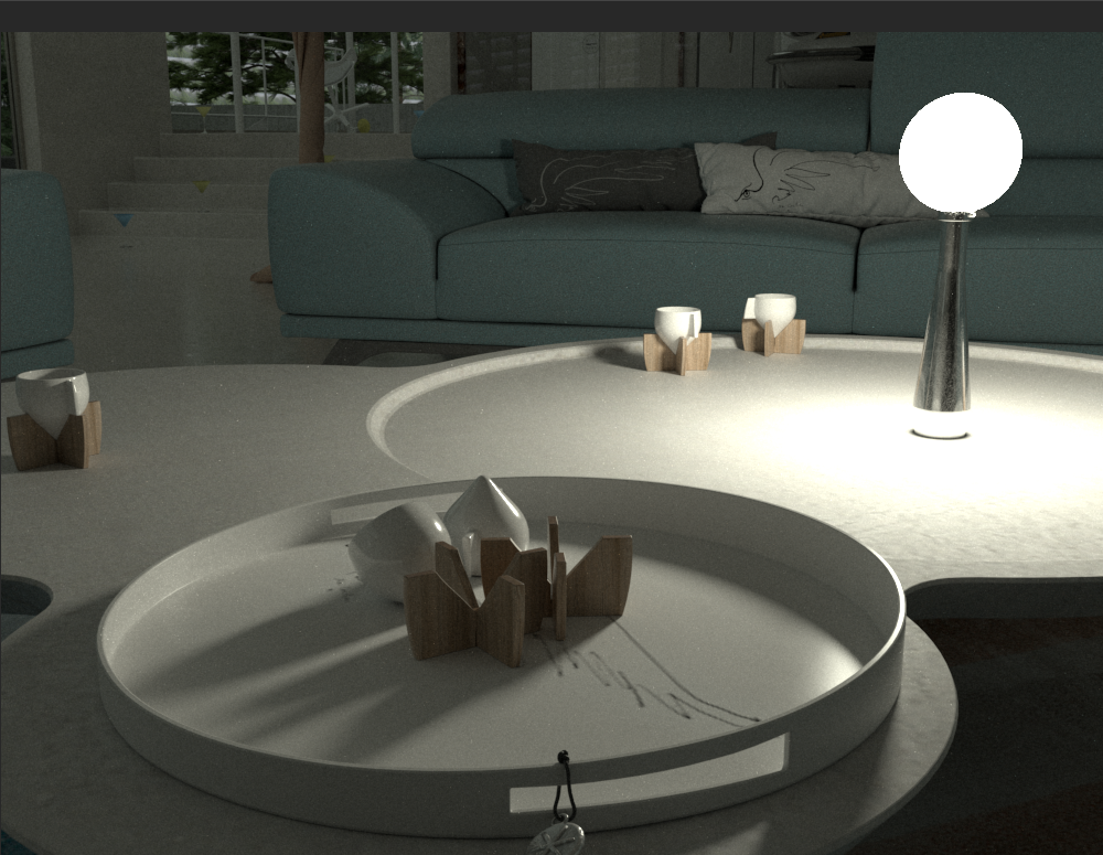
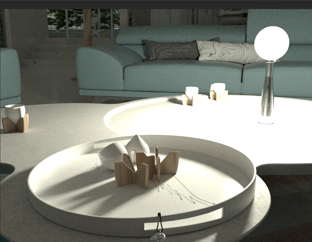
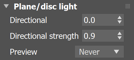
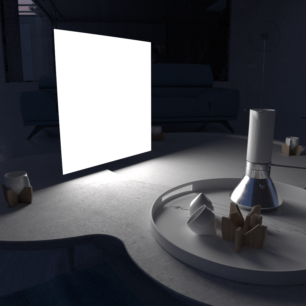
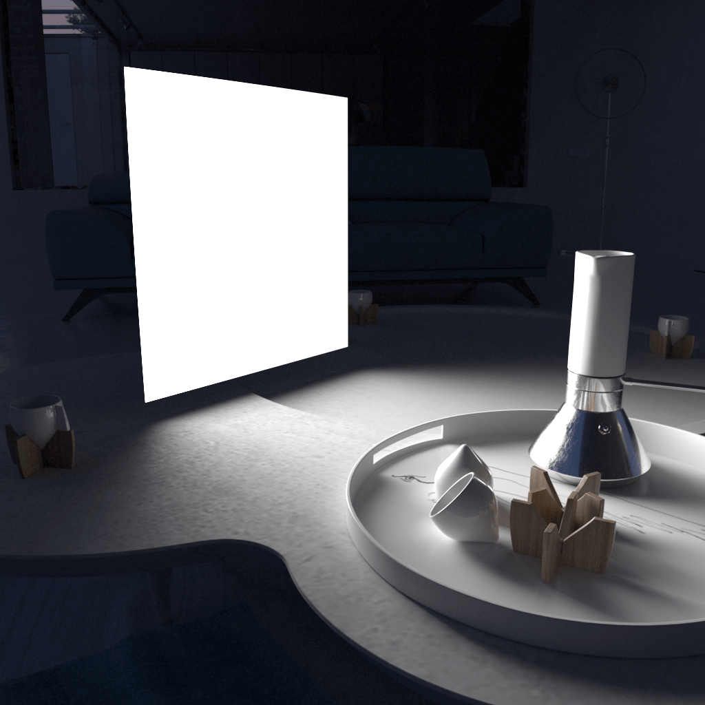
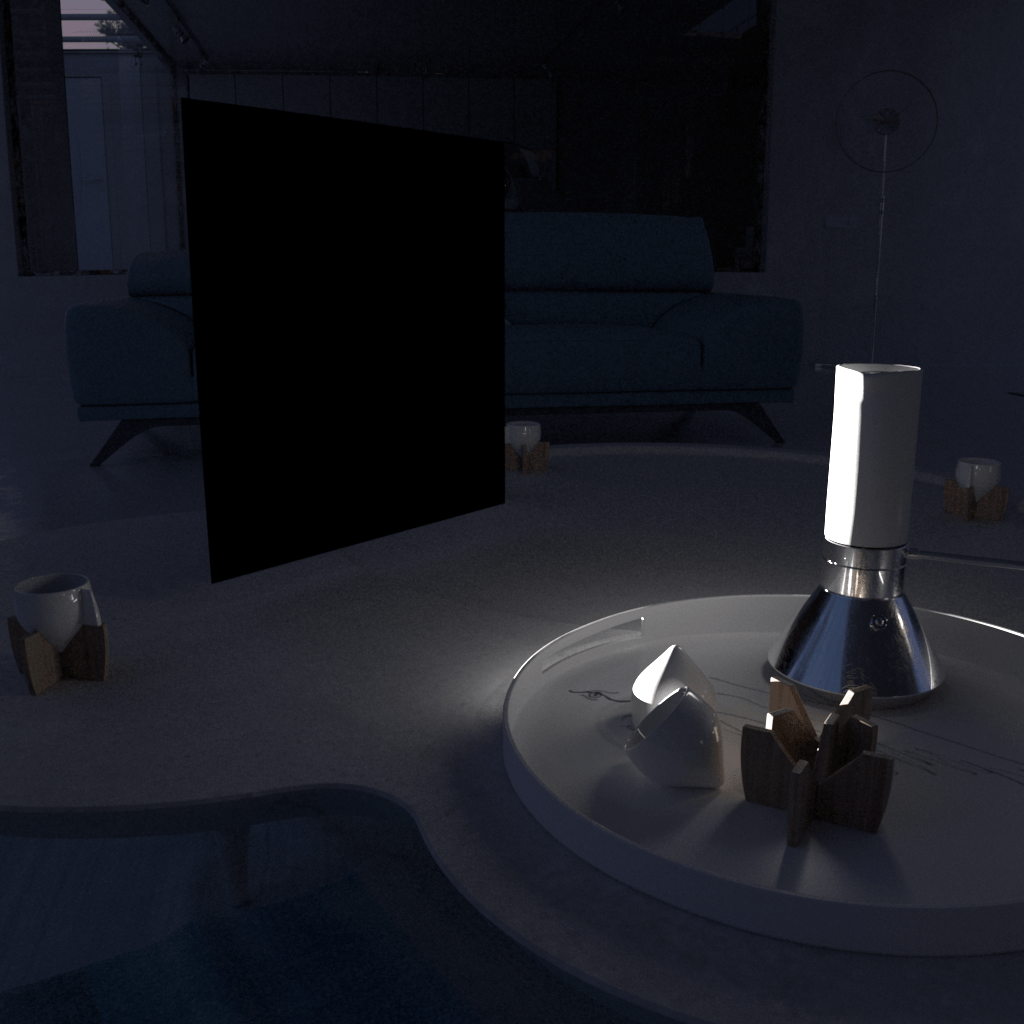
The Directional parameter controls the spread of the Plane or Disc light. A value of 0 produces the maximum spread of light in all directions as seen in figure 1, while a value of 1 creates a narrow light beam as seen in figure 3.


Section
Column
width20%


Column
width60%

Column
width20%


Plane light with Directional = 0, 0.5, 1.0
Preview = Always

...


The following example shows the effect of the Directional parameter. Note that the plane light itself appears to turn black as the value gets closer to 1.0. This is due to the simplified directional distribution. The light is forced only in the forward direction, so the plane appears dark when viewing it from the side. This phenomenon does not occur with real-world lights because they exhibit more complex directional distribution. 


Section
 
Column
width25%


Column
width50%
Image slider
Panel
borderStylenone

Directional = 0.0

Panel
borderStylenone

Directional = 0.6

Panel
borderStylenone

Directional = 0.8

Panel
borderStylenone

Directional = 1.0

Column
width25%


...


...


Anchor
Options
Options

Parameters - Options Rollout

...

Section
Column
width60%

Exclude – Opens the 3ds Max Exclude/Include window for selection of objects to be excluded or included in illumination and/or shadow-casting for this light.

Cast shadows – When enabled (the default), the light casts shadows. Turn this option off to disable shadow casting for the light.

Double-sided – When the light is a Plane or Disc type, this option controls whether light is beamed from both sides of the light icon. This field has no effect for Sphere type of light source. For more information, see The Single-Sided vs Double-Sided Lights example below.

Invisible – Controls whether the shape of the light source is visible in the rendered image. When this option is disabled, the light source is rendered in the color specified by the Color or Temperature setting in the Intensity rollout. This option only affects the visibility of the light when seen directly by the camera or through refractions. The visibility of the light with respect to reflections is controlled by the Affect reflections option.

Note: Regardless of whether this option is enabled, the light source is still taken into account by Global Illumination calculations, which might cause secondary GI rays to be blocked by or bounced off the light's surface. To make the light completely invisible to GI, place a VRayColor texture map into the light's texture slot and set the alpha value for the VRayColor map to 0.0.

Occlude other lightsControls the behavior of invisible lights in relation to other light sources. When enabled, the light blocks the lighting from other lights as if it's visible. Also in reflections the light behaves as it's visible and occludes other lights. When disabled, the light is transparent for other lights and does not occlude them. This option doesn't affect visible lights (as they always occlude other lights) and dome lights (which are always additive).

Affect diffuse – Determines whether the light affects the diffuse portion of the materials. The value controls the light's contribution to the diffuse portion of the materials.

Affect specular – Determines whether the light affects the specular portion of the materials. The value controls the light's contribution to specular reflections.

Affect reflections – Specifies whether the light source appears in reflections.

Affect atmospherics - Specifies whether the light influences the atmospheric effects in the scene. The value determines the amount of involvement.

Column
width5%


Column
width35%


Anchor
SSvsDS
SSvsDS

...

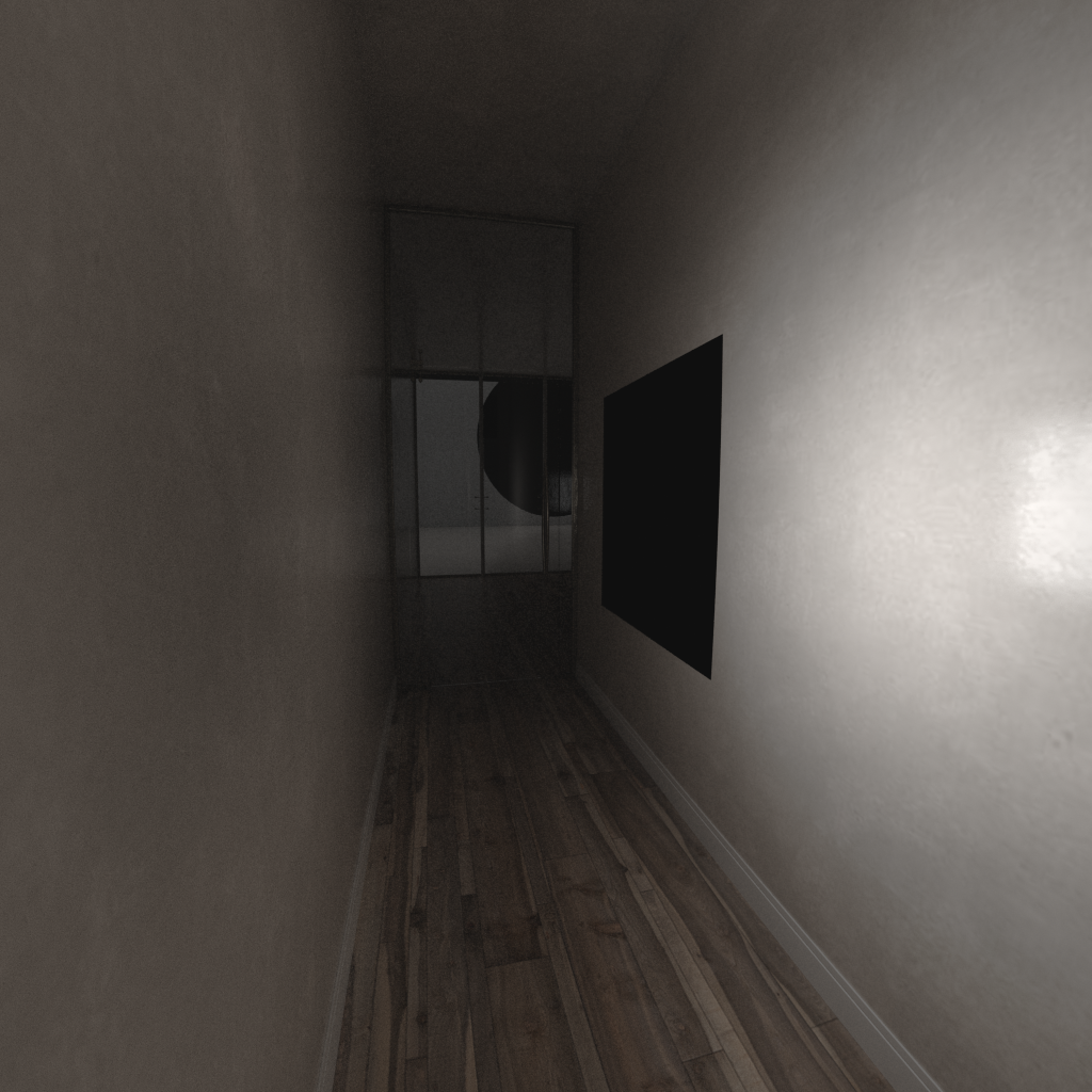
Example: Single-Sided vs Double-Sided Lights

...

This example demonstrates how a Plane light is affected when the Double-sided option on the Options rollout is enabled or disabled. The light is pointed away from the hallway. 


The VRayLight in the viewport.


Section
 
Column
width25%


Column
width50%
Before after
afterLabelEnabled
beforeLabelDisabled
Panel
borderStylenone

Panel
borderStylenone

 
Column
width25%


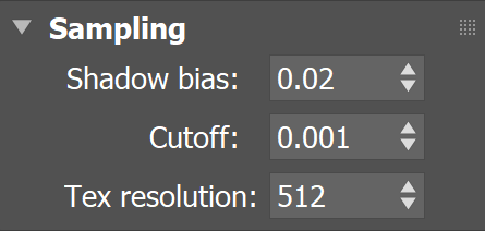
Parameters - Sampling Rollout

...

Section
Column
width60%

Shadow bias – This value moves the shadow toward or away from the shadow-casting object (or objects). Higher values move the shadow toward the object(s), while lower values move it away. If this value is too extreme, shadows can "leak" through places they shouldn't or "detach" from an object. Other effects from extreme values include Moire patterns, out-of-place dark areas on surfaces, and shadows not appearing at all in the rendering.

Cutoff – Specifies a threshold for the light's intensity, cutting off the light's effect on a surface when it falls below this value. Lights lose intensity due to GI bouncing or decay. When light hits a surface but its intensity falls below the cutoff, the effect of the light on that surface is not computed. This can be useful in scenes with many lights, where you want to limit the effect of the lights to some distance around them or reduce computations (and thus reduce rendering time) where the light's impact is negligible. Larger values limit the light's effect on objects to a smaller area around the light source, while lower values increase the range of the light's effect. If you specify 0.0, there is no cutoff and the light is calculated for all surfaces regardless of intensity loss. The default value is 0.001. This parameter is not available when the renderer is set to GPU.

Tex resolution – Specifies the resolution at which the texture is resampled for importance sampling.

 
Column
width5%


Column
width35%

...


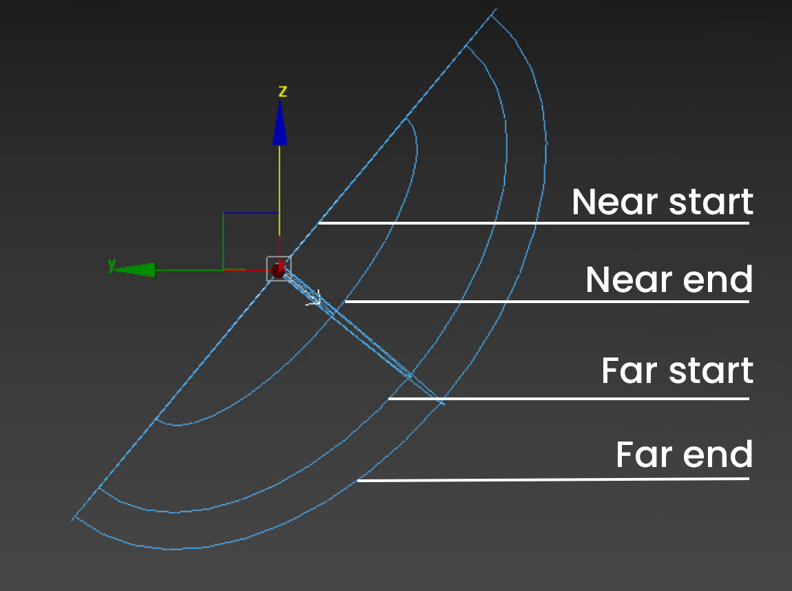
Parameters - Decay Rollout

...

The Decay parameters determine how the light fades in and out. The Near Decay determines how light fades in. The light isn't at its maximum value at its source, but instead gradually increases until it reaches the Near end. The Far Decay determines how light fades out. The light isn't at its maximum value at its end, but instead gradually decreases after the Far start.

Section
Column
width25%
 

Column
width50%

Column
width25%


Section
Column
width60%

Near on – Toggles near decay on and off. See the Near decay examples below for more information.

Near start – Determines where the fade in starts. Anything before this point is rendered dark.

Near end – Determines where the fade in ends. After this threshold, the light is at its full value.

Far on – Toggles far decay on and off. See the Far decay examples below for more information.

Far start – Determines where the fade off starts.

Far end – Determines where the light reaches a value of 0, i.e. completely fades off.

Preview - Determines whether light decay is visible in the viewport. Refer to the Preview Gizmo graphic to see how the Preview looks in the viewport.

Selected – Light decay is visible only when the light is selected.
Always – Light decay is always visible in the viewport, even when the light is not selected.
Never – Light decay is not visible in the viewport.

 
Column
width5%

Column
width35%


Anchor
previewGraphic
previewGraphic

...

Preview Gizmo

Section
 
Column
width25%

Column
width50%

Column
width25%


...


...

Anchor
near
near

Section
 
Column
width5%


Column
width35%

Example: Near Decay Start

This example shows the variances achieved by changing the Near decay start parameters only.

Image slider
Panel
borderStylenone

Near decay start 10, Near decay end 60

Panel
borderStylenone

Near decay start 30, Near decay end 60

Panel
borderStylenone

Near decay start 50, Near decay end 60

Column
width10%


Column
width35%

Example: Near Decay End

This example shows the variances achieved by changing the Near decay end parameters only.

Image slider
Panel
borderStylenone

Near decay start 0, Near decay end 10

Panel
borderStylenone

Near decay start 0, Near decay end 30

Panel
borderStylenone

Near decay start 0, Near decay end 50

Column
width5%


...

Anchor
far
far

Section
 
Column
width5%


Column
width35%

Example: Far Decay Start

This example shows the variances achieved by changing the Far decay start parameters only.

Image slider
Panel
borderStylenone

Far decay start 10, Far decay end 60

Panel
borderStylenone

Far decay start 30, Far decay end 60

Panel
borderStylenone

Far decay start 50, Far decay end 60

Column
width10%


Column
width35%

Example: Far Decay End

This example shows the variances achieved by changing the Far decay end parameters only.

Image slider
Panel
borderStylenone

Far decay start 60, Far decay end 60

Panel
borderStylenone

Far decay start 60, Far decay end 100

Panel
borderStylenone

Far decay start 60, Far decay end 120

Column
width5%


...


...


Section
Column
width35%


Column
width35%

Example: Near and Far Decay

This example shows some artistic lighting results achieved by using both Near and Far decay options.

Image slider
Panel
borderStylenone

Near decay start 0, Near decay end 15, Far decay start 30, Far decay end 60

Panel
borderStylenone

Near decay start 20, Near decay end 35, Far decay start 40, Far decay end 55

Panel
borderStylenone

Near decay start 30, Near decay end 60, Far decay start 90, Far decay end 120

Column
width30%


...


Parameters -  Viewport Rollout

...

Section
Column
width60%

Enable viewport shading – When enabled, the effect of the light is visible in the viewport. 

Viewport wire color – When enabled, the light's wireframe is displayed in the specified color in viewports.

Intensity rays – Helps with setting the desired streaks size of lights. This is just a visual tool and it depends on the Multiplier value under the General rollout. When the multiplier is increasing, the viewport indicators for VRayLight are expanding. If the multiplier is decreasing, the indicators are shrinking. See the Intensity Rays example below.

Icon text – Enables or disables the preview of the light name in the viewport.

Column
width5%


Column
width35%

...


Anchor
IntRaysEx
IntRaysEx

...


Example: Intensity Rays


Section
Column
width25%


Column
width50%

Image Added

Column
width25%


Anchor
Notes
Notes

Notes

...

Fancy Bullets
typecircle
  • When using texture-mapped Plane lights, it is best to have GI enabled. This allows V-Ray to use combined direct and indirect sampling for the light, which greatly reduces the noise for surfaces close to the light.

  • The effect of all textured V-Ray lights can be shown through the Nitrous preview in the viewport.
  • When an Area light is visible in a rendering, the edges of the light source can appear to be aliased. This happens because the light source color is usually very, very bright, far beyond the range of what an ordinary monitor can display, and antialiasing involves changing the colors of pixels at the edges of objects to a color midway between two other colors. When V-Ray applies antialiasing to a light source's edges, any colors midway between the light color and surrounding object colors are still very bright, beyond what a monitor can display, and the pixels that are supposed to provide a smooth transition from the light source to the surrounding objects appear to be the same color as the light source. As a result, there appears to be no antialiasing at all around the light source. To solve this problem, use a VRaySoftbox texture on the light source to cause its brightness to reduce at the edges, or use Lens Effects to soften and blur the aliased edges of the lights after rendering.