![]()
Page History
This page provides information about the Toon Override material in V-Ray for SketchUp.
Overview
...
| Section | ||||||||||||||||||||
|---|---|---|---|---|---|---|---|---|---|---|---|---|---|---|---|---|---|---|---|---|
|
UI Path
...
||V-Ray Asset Editor|| > Materials (right-click) > Toon Override
||V-Ray Asset Editor|| > Materials (left-click) > Toon Override
UI Options
...
| Section | |||||||||||||||
|---|---|---|---|---|---|---|---|---|---|---|---|---|---|---|---|
|

...
Contour
| Section | ||||||||||||||||||||
|---|---|---|---|---|---|---|---|---|---|---|---|---|---|---|---|---|---|---|---|---|
|

Override Control
Can be Overridden – When enabled, the material can be overridden by the Material Override option in the Settings.
Attributes
The attributes from the following expandable menus are available for the Toon Override material.
| Anchor | ||||
|---|---|---|---|---|
|
| Expand | |||||||||||||||||
|---|---|---|---|---|---|---|---|---|---|---|---|---|---|---|---|---|---|
| |||||||||||||||||
Translucency
|
| Expand | |||||||||||||||||
|---|---|---|---|---|---|---|---|---|---|---|---|---|---|---|---|---|---|
| |||||||||||||||||
Bump
|

| Expand | |||||||||||||||||||||||||||
|---|---|---|---|---|---|---|---|---|---|---|---|---|---|---|---|---|---|---|---|---|---|---|---|---|---|---|---|
| |||||||||||||||||||||||||||
Displacement
|

| Expand | |||||||||||||||||
|---|---|---|---|---|---|---|---|---|---|---|---|---|---|---|---|---|---|
| |||||||||||||||||
Raytrace Properties
|

| Expand | |||||||||||||||||
|---|---|---|---|---|---|---|---|---|---|---|---|---|---|---|---|---|---|
| |||||||||||||||||
Override
|
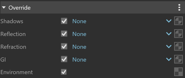
| Expand | ||||||||||||||||||||||
|---|---|---|---|---|---|---|---|---|---|---|---|---|---|---|---|---|---|---|---|---|---|---|
| ||||||||||||||||||||||
Material ID
|
