This page provides information on V-Ray's photometric lights.
Overview
Photometric lights utilize an .ies file which contains the distribution profile for the light. An .ies file contains complete specifications of a real world light bulb or tube including the shape of the light's cone and the steepness of the light's falloff. Such files are usually provided by the manufacturer of the real-world bulb, and the information in those files, gathered through lab experiments, is extremely accurate in its representation of the light source. By loading an .ies file, the light's properties are recreated within Maya and used by V-Ray during rendering.
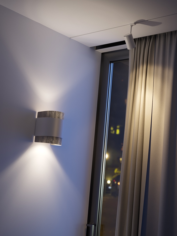
IES lights are particularly useful for architectural interior renderings, where it can be important to show an accurate representation of the use of specific man-made light sources in the scene.
||V-Ray Shelf|| > VRayLightIES button

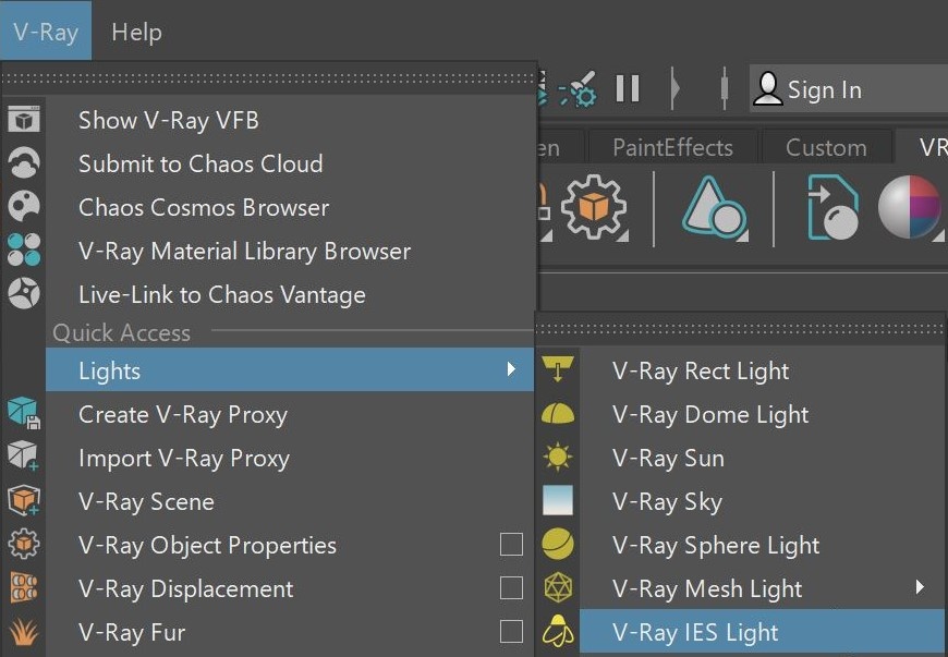
||V-Ray menu|| > Lights > V-Ray IES Light
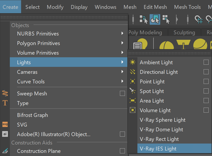
||Create menu|| > Lights > V-Ray IES Light
You can create a VRayLightIES object with a light profile loaded in it by dragging and dropping an .ies file directly in your active viewport.
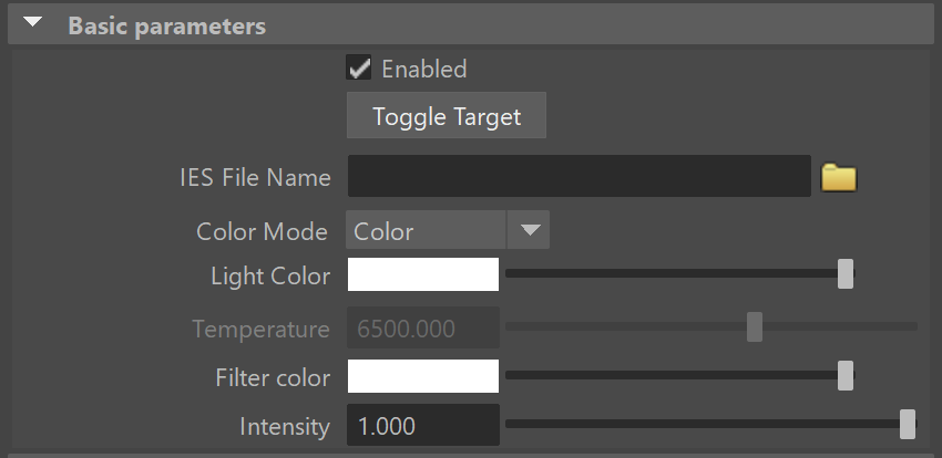
Basic Parameters
Enabled – Turns the light on and off.
Toggle Target – Switches the light between being targeted and not targeted (free light). The Maya default "t" hotkey can also be used.
IES File Name – Load an .ies file to use for the current light.
Color Mode – Chose the mode in which the color of the light will be specified.
Light Color – When Color Mode is set to Color, controls the color of the light. When using photometric units, this color is normalized so that only the color hue is used, whereas the light intensity is determined by the Intensity parameter.
Temperature – When Color Mode is set to Temperature, this parameter controls the color of the light.
Filter color – A color multiplier for the light.
Intensity – An intensity multiplier of the light.
Shadows
Shadows – When enabled (default), the light casts shadows. Turn this option off to disable shadow casting for the light.
Soft Shadows – Sometimes the .ies file contains information about the physical shape and size of the bulb. When this option is enabled the light will cast shadows according to this information. Otherwise the light will cast shadows as if it was a Point Light.
Shadow bias – Moves the shadow toward or away from the shadow-casting object (or objects). Higher values move the shadow toward the object(s), while lower values move it away. If this value is too extreme, shadows can "leak" through places they shouldn't or "detach" from an object. Other effects from extreme values include moire patterns, out-of-place dark areas on surfaces, and shadows not appearing at all in the rendering.
Shadow Color – Controls the color of shadows for this light. Note that anything different from black is not physically correct. This options is inactive when using the V-Ray CUDA engine.

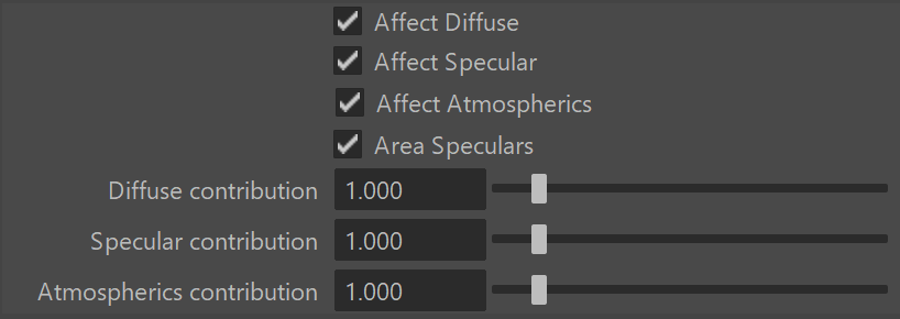
Options
Affect Diffuse – Determines whether the light is affecting the diffuse properties of the materials.
Affect Specular – Determines whether the light is affecting the specular of the materials. This means glossy reflections.
Affect Atmospherics – When enabled, the light influences the atmospheric effects in the scene.
Area Speculars – When enabled, the specular highlights are computed with the real light shape as defined in the .ies files. For this to work you also have to enable Soft Shadows. When this parameter is disabled, the specular highlights are computed using a point light approximation instead of the real shape.
Diffuse contribution – A multiplier for the effect of the light on the diffuse.
Specular contribution – A multiplier for the effect of the light on the specular.
Atmospherics contribution – Determines the amount of influence the light has on the atmospheric effects such as VRayEnvironmentFog, VRayVolumeGrid or Phoenix effects.
Sampling
Light cutoff threshold – Specifies a threshold for the light intensity, below which the light will not be computed. This can be useful in scenes with many lights, where you want to limit the effect of the lights to some distance around them. Larger values cut away more from the light; lower values make the light range larger. If you specify 0.0, the light will be calculated for all surfaces. This parameter is not available when the renderer is set to CUDA.
Override motion blur samples – Overrides the default number of samples that are used to sample the current light for motion blur.
Motion blur samples – When Override motion blur samples is enabled, this value is used when sampling the motion blur created by the current light.

Decay
The Decay parameters determine how the light fades in and out. The Near decay determines how light fades in. The light isn't at its maximum value at its source, but instead gradually increases until it reaches the Near end. The Far decay determines how light fades out. The light isn't at its maximum value at its end, but instead gradually decreases after the Far decay start.
Decay option is useful for creating hotspots or controlling the length of a "God Rays" effect created with Environment Fog.

Near decay on – Toggles near decay on and off. See the Near examples below for more information.
Near decay start – Determines where the fade in starts. Anything before this point is rendered dark.
Near decay end – Determines where the fade in ends. After this threshold, the light is at its full value.
Far decay on – Toggles far decay on and off. See the Far examples below for more information.
Far decay start – Determines where the fade off starts.
Far decay end – Determines where the light reaches a value of 0, i.e. completely fades off.

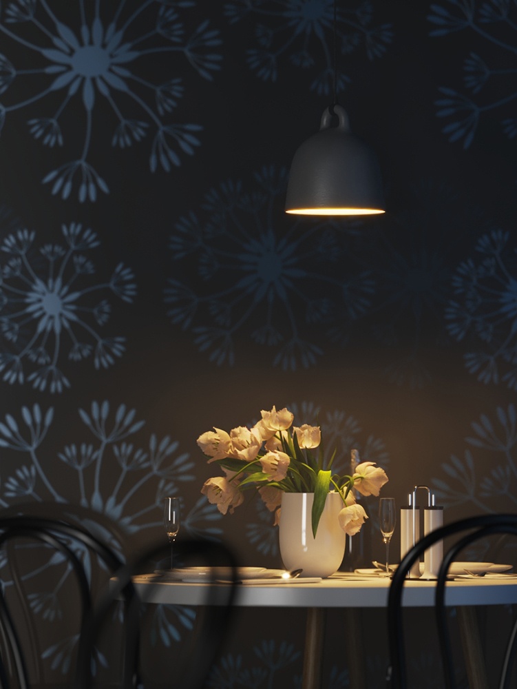
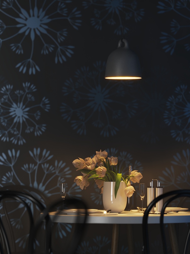
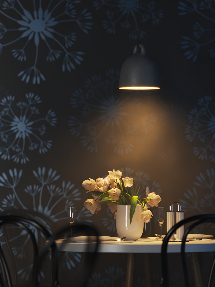
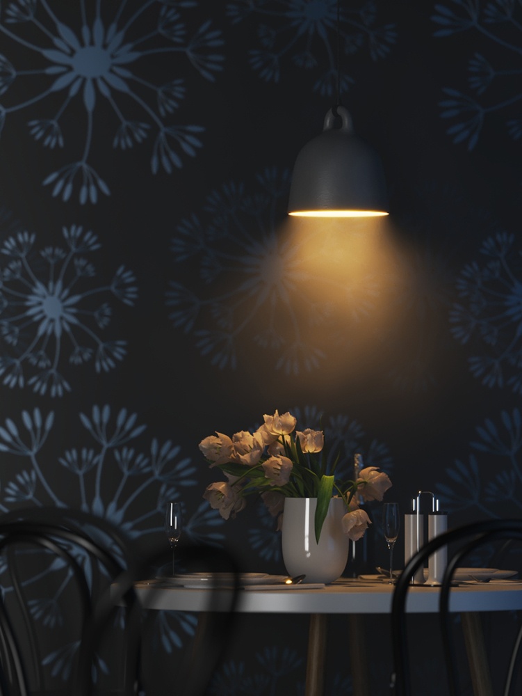
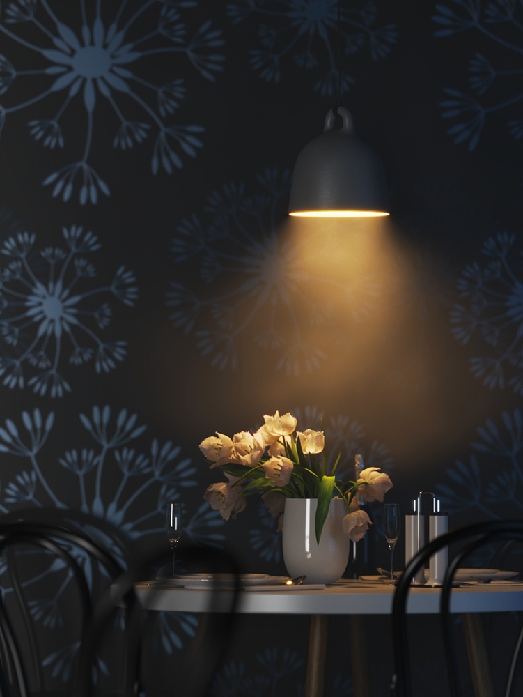
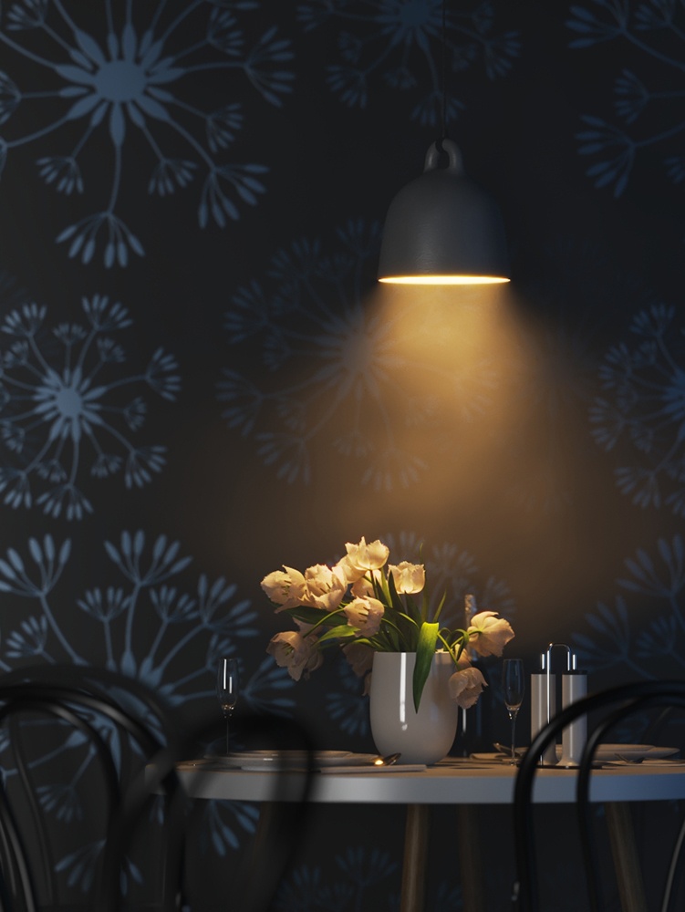
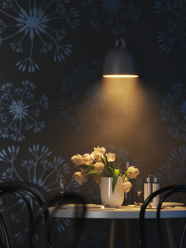
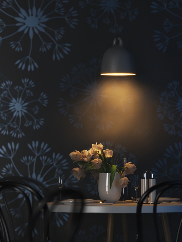
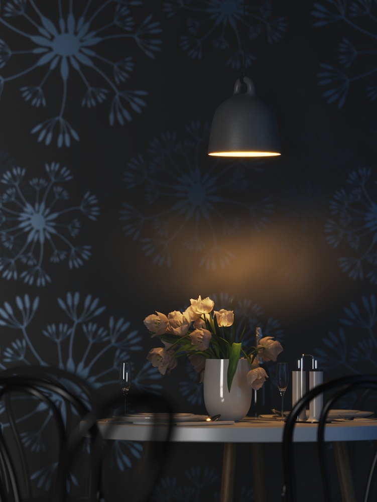
This example shows the variances achieved by changing the Near decay start parameters only. Near decay start 10, Near decay end 60 Near decay start 30, Near decay end 60 Near decay start 50, Near decay end 60 This example shows the variances achieved by changing the Near decay end parameters only. Near decay start 0, Near decay end 10 Near decay start 0, Near decay end 30 Near decay start 0, Near decay end 50 This example shows the variances achieved by changing the Far decay start parameters only. Far decay start 10, Far decay end 60 Far decay start 30, Far decay end 60 Far decay start 50, Far decay end 60 This example shows the variances achieved by changing the Far decay end parameters only. Far decay start 60, Far decay end 60 Far decay start 60, Far decay end 100 Far decay start 60, Far decay end 120 This example shows some artistic lighting results achieved by using both Near and Far decay options. Near decay start 0, Near decay end 15, Far decay start 30, Far decay end 60 Near decay start 20, Near decay end 35, Far decay start 40, Far decay end 55 Near decay start 30, Near decay end 60, Far decay start 90, Far decay end 120 Example: Near Decay Start
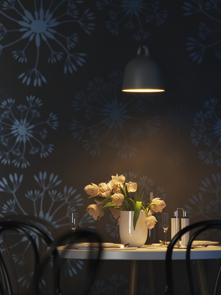
Example: Near Decay End


Example: Far Decay Start

Example: Far Decay End

Example: Near and Far Decay

Photon Emission
This rollout is inactive when using V-Ray GPU.
Caustics subdivs – Used by V-Ray when calculating Caustics. Lower values mean more noisy results, but render faster. Higher values produce smoother results but take more time.
Caustics multiplier – A multiplier for the generated caustics by the selected object. Note that this multiplier is cumulative - it does not override the multiplier in the Caustics render rollout section.

UI
Locator Scale – Multiplies the size of the locator in the viewport. This does not affect the render.

Light Shape
Light Shape – Determines the shape of the light when calculating Soft Shadows. By default, VRayLightIES uses the shape information stored in the .ies file. Overrides for the light shape can be specified from the list below.
- Point
- Rectangular
- Circular
- Sphere
- Vertical cylinder
- Horizontal cylinder oriented along lum. length
- Horizontal cylinder oriented along lum. width
- Ellipse oriented along luminaire length
- Ellipse oriented along luminaire width
- Ellipsoid oriented along luminaire length
- Ellipsoid oriented along luminaire width
See the Light Shape example below.
Width – Specifies the width for applicable Light Shape types.
Length – Specifies the length for applicable Light Shape types.
Height – Specifies the height for applicable Light Shape types.
Diameter – Specifies the diameter for applicable Light Shape types.

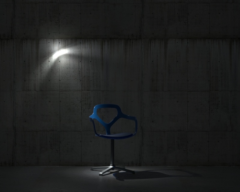
Example: Light Shape
This example shows how light is affected by the different shapes of the IES Light. Circle and Sphere shapes examples are also compared with different diameters - 1.0 and 10.0.

Circular, Diameter = 1.0

Circular, Diameter = 10.0

Default shape From the IES light
Point

Sphere, Diameter = 1.0
Sphere, Diameter = 10.0