This article explains the settings and values for the Chaos Scatter object.
You are viewing technical documentation of Chaos Scatter for Corona for Cinema 4D. To learn more about usage examples, troubleshooting, and using Chaos Scatter with other features of Corona, please see this Help Center article.
Overview
Chaos Scatter lets you quickly and efficiently populate surfaces, splines, and volumes with vast numbers of objects. Its major features include:
- A library of ready-to-use presets is available in Chaos Cosmos
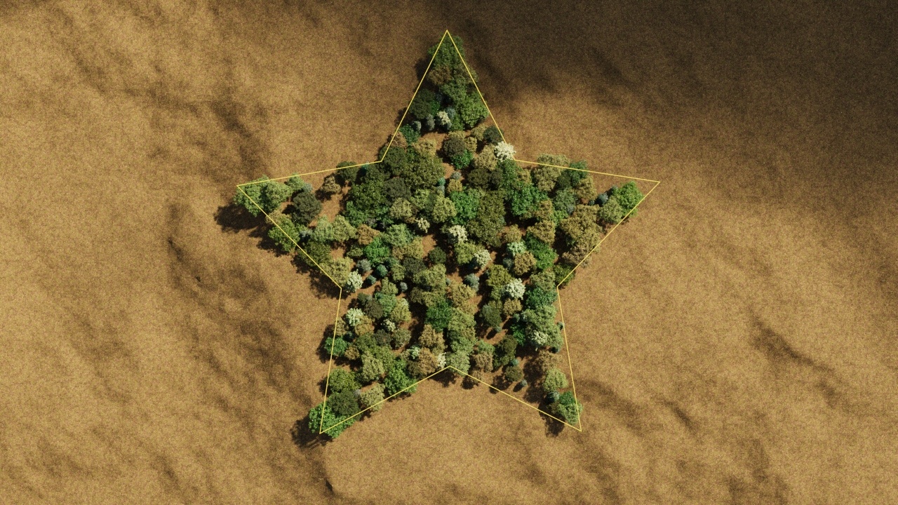
- Edge trimming (removing any elements of scattered models that stick outside of the defined area)
- Slope limiting for the scattered instances (no trees growing out of cliffs)
- Including/excluding scattering areas using splines (closed or open)
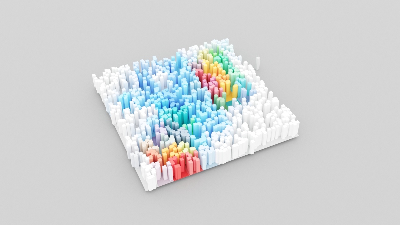
- Surface color shader (coloring scattered instances based on pattern textures on rugs, ground, etc.)
- Limiting scattering only inside the camera field of view (camera clipping)
- Efficient viewport display
- and more...

Tutorial: Using Chaos Scatter with Corona for Cinema 4D
Object Properties
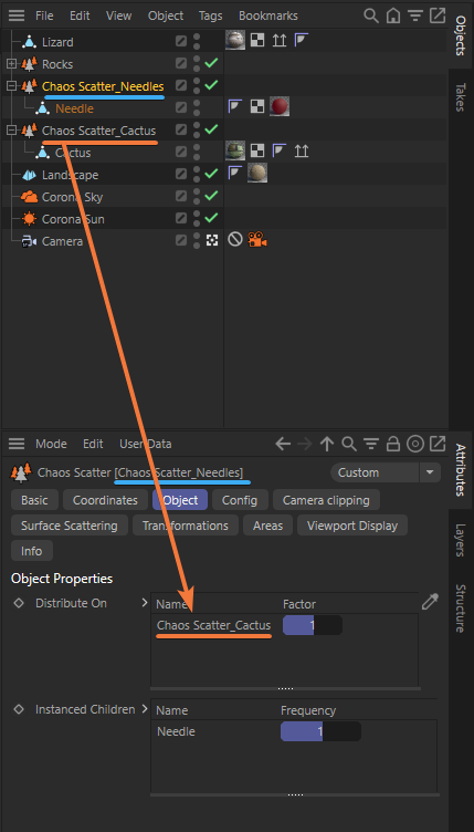
Distribute On – List of scene objects used as the base for distributing the scattered instances.
Factor – In either case, if the scattering is defined just by the Count option, it works as a relative weight factor determining how many instances get scattered for the currently selected distribute-on object. Alternatively, in case of scattering instances to reach some density defined by Count and Per square/cube options, it works as a density factor (multiplier) affecting the final density there.
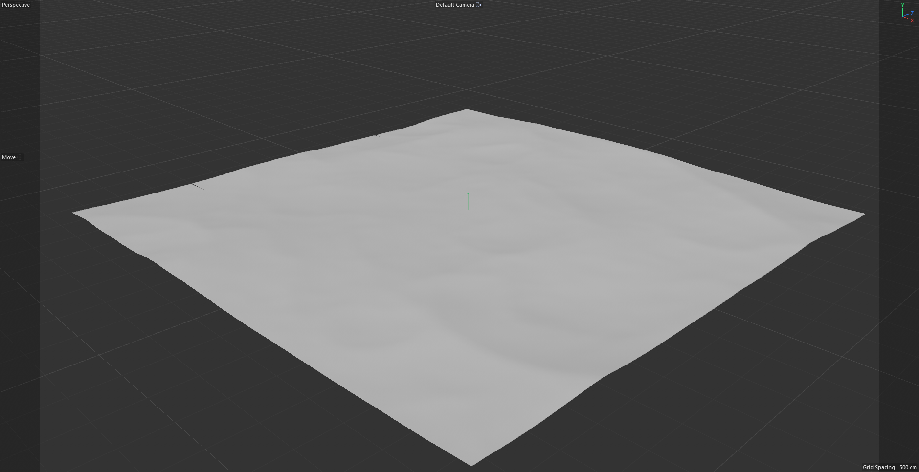
Drag & drop any object to use it as the base surface to scatter objects.
The Factor is disabled in case a spline is used as the distribution object
Instanced Children – List of scene objects that are being scattered on the distribute-on objects.
Frequency – Available only if there is more than one instanced object. Sets the frequency of the currently selected instanced object relative to others.
Only the nested objects (children) into the Chaos Scatter object are considered as the Instanced children.


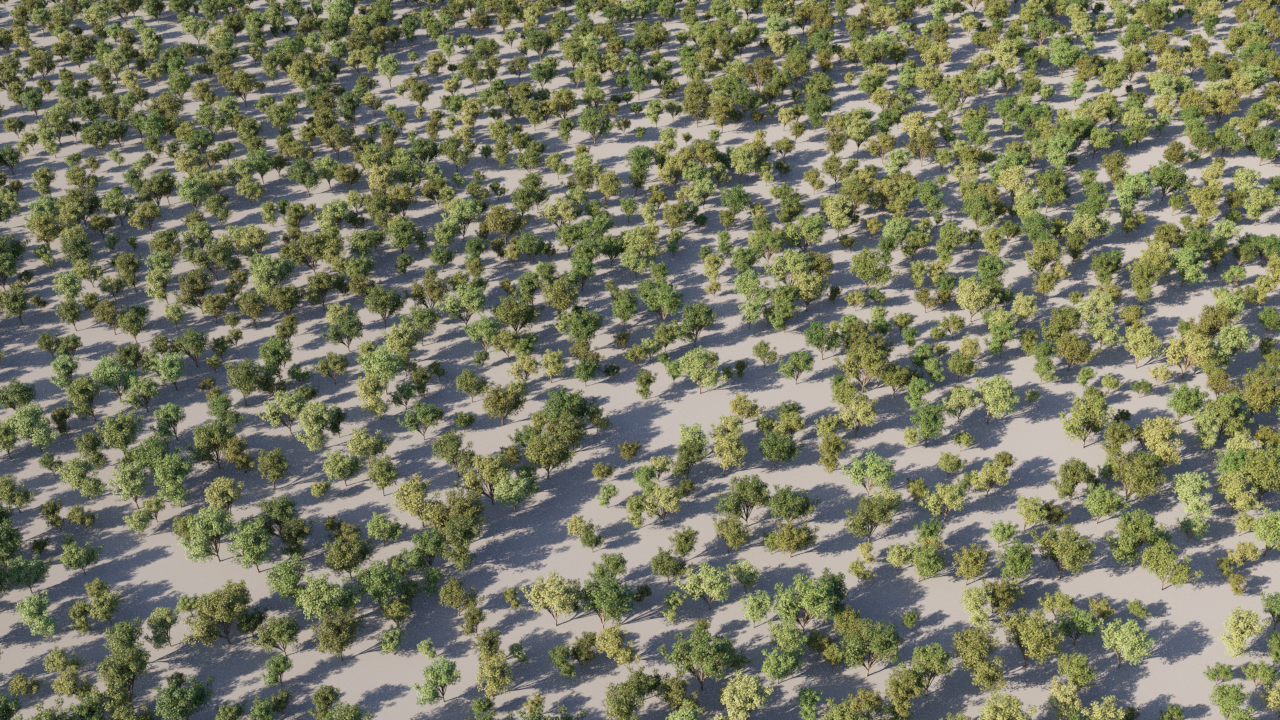
In the case of scattering trees on the ground, the tree models are used as Instanced (nested) objects, and the ground plane is used as the Distribute-on object.
Config
Max limit – Limits the maximum number of scattered instances. Note that there is always another mode-dependent parameter (spacing, density, or count) that determines how many instances to scatter. This parameter is intended as a constant value "safety measure" to prevent crashes/freezes from scattering too many instances, e.g., when setting the density too high.
Random seed – Determines the particular random distribution used. Changing the value makes random permutations of the scattered objects.
Scattering mode – Allows selecting between different scattering modes. Available scattering modes are:
1D - On splines – Scatters instances along splines. Works with both open and closed splines.
2D - On surfaces – Scatters instances on the surface of the selected objects. Works with closed splines too, treating the spline area as the surface to scatter on.
3D - In bounding box – Scatters instances inside the bounding boxes of the selected objects.
Avoid collisions – When enabled, the instances that collide with other ones are discarded, resulting in no overlaps between instances. Note that when using this feature, the real number of created instances may be lower than the number specified in the settings.
Spacing – This value is a multiplier for enlarging/shrinking the bounding boxes used to detect and remove collisions of the scattered objects. Use lower values to achieve a higher density of the scattered objects at the cost of some minor collisions. Use higher values to keep scattered objects farther apart from each other.

Example: Scattering mode


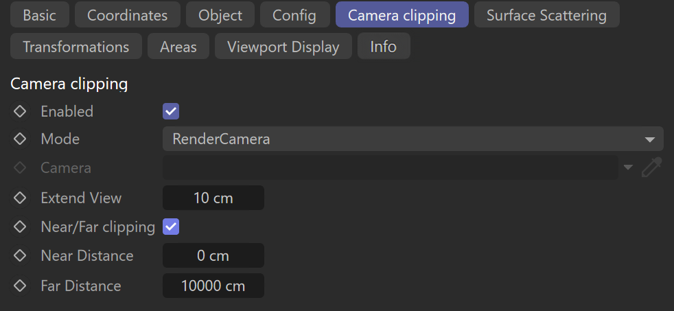
Camera clipping
Enabled – When enabled, scattering is limited only to the camera view, and instances that are not visible are clipped away. It is an optimization - it may improve scene parsing performance and lower memory requirements; however, it can cause missing reflections/shadows. To compensate for this, you can use the Extend view parameter.
Mode – Allows selecting between different camera clipping methods. Available modes are:
Render Camera – Clips the instances based on the active camera view used for rendering. The clipping is not visible in the viewport unless changing clipping parameters or running IR. This is because otherwise, the clipping would be too intrusive during regular scene work.
Selected Camera – Uses a selected camera for the clipping. In this case, the clipping is always visible.
Camera – Allows defining the camera used when the clipping mode is set to Selected Camera.
Extend view – Specifies a uniform extension to the camera view in all directions (as distance), adding an extra zone beyond the camera view (behind the camera too) where the instances are not clipped. This is useful for ensuring correct shadows or reflections from instances that would otherwise be clipped.
Near/Far clipping – When enabled, allows using the Near and Far distance parameters to control the camera clipping extension.
Near Distance – Specifies the near threshold distance from the camera. Instances closer than the near value are clipped away.
Far Distance – Specifies the far threshold distance from the camera. Instances farther than the far value are clipped away.
Example: Camera Clipping "Render Camera"


Example: Camera Clipping "Selected Camera"


Example: Camera Clipping "Extend View"


The camera clipping is purely an optimization feature! It can speed up scene parsing and lower memory usage by hiding some of the rendered objects that would be otherwise visible and, therefore, would need to be parsed and allocated in the memory. It must NEVER be used to limit the scattered instances to a specific area. Other features should be used for this, such as spline include/exclude and slope limitation!
If you are experiencing a lag in the viewport due to camera clipping being enabled, you can disable ''Immediate updates'' from within the Viewport Display settings, which will then only update scatter objects in your scene when releasing the mouse button.
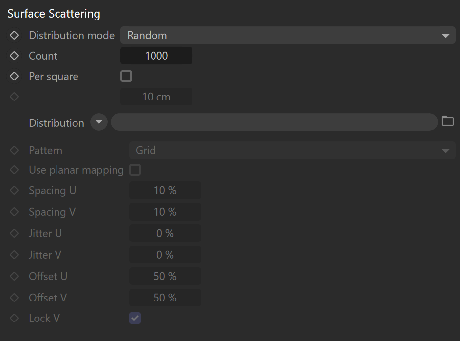
Surface Scattering
Distribution mode – Allows selecting between different distribution modes. Available distribution modes are:
Random – Scatters randomly on all mesh and closed spline distribution objects.
UV – Uses the distribution objects' UVW mapping to scatter the instances in regular patterns.
Count – Defines an exact number of instances to scatter - either overall or per area in the case of scattering defined by density (Per square option). The number is always limited by the Max. limit option.
Per square – When enabled, the number of instances to scatter is defined by density (Count per square having the given edge length). The number of instances is always limited by the Max. limit option. The specified value is the edge length of a square defining an area for computing the scatter density.
Distribution – Specifies a texture map or shader used for instance distribution. White areas of the texture are treated as maximum density, and black areas are treated as areas with no instances.
Count, Per square, and distribution parameters are only available when the distribution mode is set to Random.
Pattern – Allows to select between different distribution patterns. Choose which pattern to use for scattering:
Grid – Rectangular grid.
Running grid – Rectangular grid with every other row offset by half of the grid spacing.
Hexagonal grid – Hexagonal point arrangement.
Use planar mapping – When enabled, simple planar UVW mapping is applied to the distribution object and used instead of its existing UVW channel.
Spacing U – Scales the pattern in the U axis - 100% spacing makes the pattern occupy the whole 0-1 UV space; with 50% spacing, the pattern gets repeated 2 times in U.
Spacing V – Scales the pattern in the V axis - 100% spacing makes the pattern occupy the whole 0-1 UV space; with 50% spacing, the pattern gets repeated 2 times in V.
Jitter U – Randomly jitters each instance in the U axis, with 0% being entirely deterministic placement (no jitter) and 100% being entirely random placement.
Jitter V – Randomly jitters each instance in the V axis, with 0% being entirely deterministic placement (no jitter) and 100% being entirely random placement.
Offset U – Offsets the pattern in the U axis. Each 100% added or subtracted moves the pattern by one entire repetition - which means that, e.g., 0% and 100% offsets yield the same result.
Offset V – Offsets the pattern in the V axis. Each 100% added or subtracted moves the pattern by one entire repetition - which means that, e.g., 0% and 100% offsets yield the same result.
Lock V – Locks the V coordinate for Spacing, Jitter, and Offset to the same value as the U coordinate.
The following parameters are only available when the distribution mode is set to UV: Patter, Use planar mapping, Spacing U/V, Jitter U/V, Offset U/V, and Lock V.
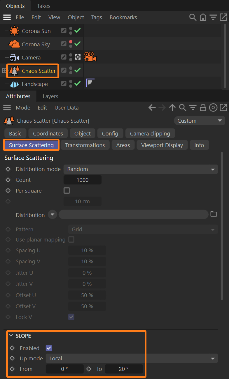
Slope
Enabled – This checkbox enables/disables the use of the slope feature.
Up mode – Allows selecting between different modes for the up axis. Available modes are:
Local – The up vector of each individual distribute-on object is used to define the slope limitation.
World – The world Y-axis up vector is used for all distribute-on objects to define the slope limitation.
From/To – These values define a range of angles, measured in degrees between either the "Local" or the "World" up vector and the surface normal, to which scattering is limited. Instances scattered outside of this range get filtered out.

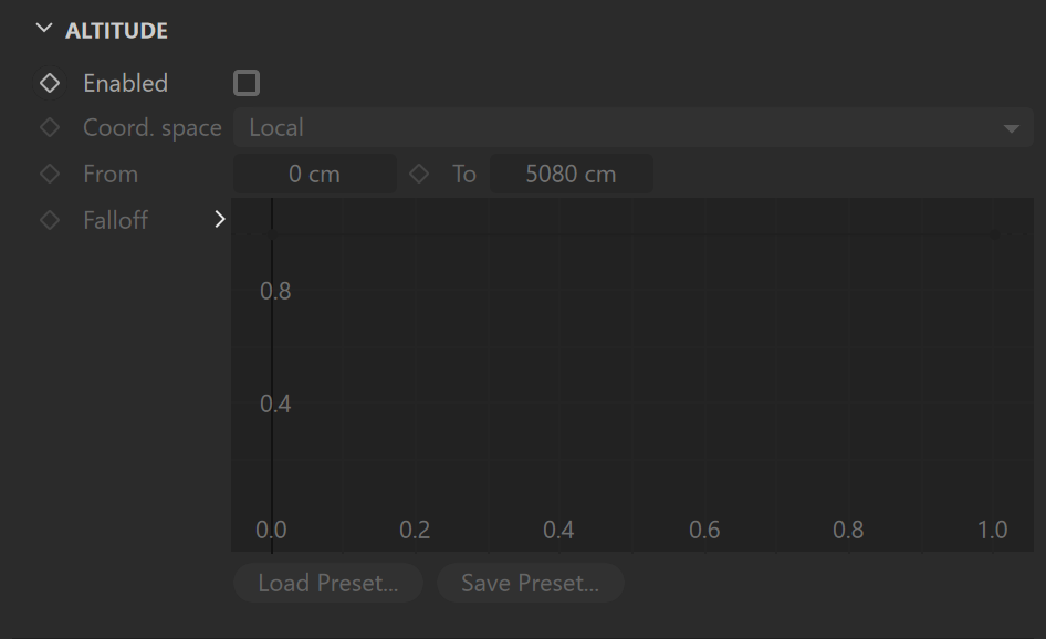
Altitude
Enabled – Enables/disables instance limitations in the given altitude range.
Coord. space – Allows selecting between different modes for the coordinate space. Available modes are:
Local – Using this mode, the altitude of the surface points on each individual distributed object is evaluated relative to the object center, while the object's rotation and scale still affect the altitude.
World – Using this mode, the altitude of the surface points on each individual distributed object is evaluated using the world coordinate system (after all transforms).
From/To – Defines the range of altitude units used to limit instance distribution on the distribution object considering the selected coordinate space.
Fallof – This fallof curve allows specifying the density of the scattered objects depending on their altitude. Lowering the point on the left side of the curve results in lowering the density of the objects closer to the minimum (From) altitude range. Lowering the point on the right side of the curve results in lowering the density of the objects close to the maximum (To) altitude range.
Example: Surface scattering

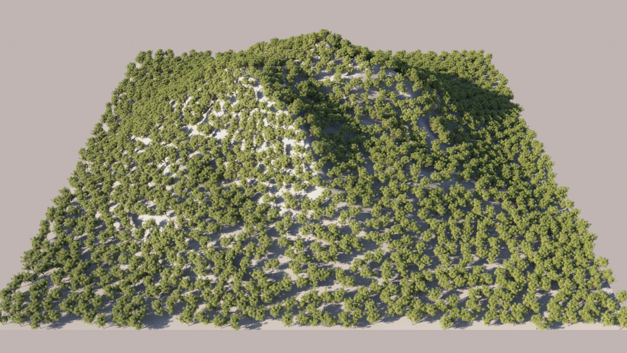


Example: Altitude limit


Transformations
Translation
From/To – Specifies the translation range for the X, Y, and Z axes, in world units.
Texture – Specifies the texture map or shader to use for translation.
Stepping – When nonzero, switches the random translation from a continuous to a discrete one, with steps specified by this parameter value. The From and To are still used as bounds. This effect is used only for the selected axes.
Step in X, Y, Z – Allows defining the axes affected by the stepping value.

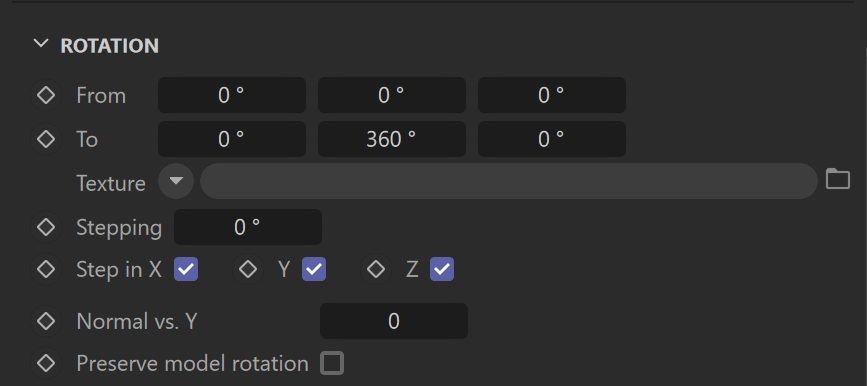
Rotation
From/To – Specifies the rotation range for X, Y, and Z axes, in degrees.
Texture – Specifies the texture map to use for rotation.
Stepping – When nonzero, switches the random rotation from a continuous to a discrete one, with steps specified by this parameter value. The From and To are still used as bounds. This effect is used only for the selected axes.
Step in X, Y, Z – Allows defining the axes affected by the stepping value.
Normal vs. Y – Allows to define the instanced object's orientation using the base object's normals. A value of 1 means instanced objects remain vertical regardless the base object's normals direction, while a value of 0 means instanced objects are oriented according to the base object's normals.
Preserve model rotation – When enabled, instances preserve the original rotation of their models (instanced objects). Otherwise, the original rotation is ignored.
Look At
Enabled – When enabled, instances in a range get turned towards a specified direction.
Target object – Allows to pick an object according to which the direction is calculated. When a geometry object is picked, each instance gets oriented towards the center of the target object's bounding box. When a camera object is picked, each instance gets oriented towards the camera.
Look axis – Selects which of the object's axes gets turned towards the direction.
Horizontal – When enabled, the selected look-at axis gets turned only within the plane which is perpendicular to the normal.
Falloff distance – Specifies the range in which instances get affected by the look-at specifications. When non-zero, only the in-range instances get affected; otherwise, all the instances get affected. Note that there is no effect when a sun object is picked.

Scale
From/To – Specifies the scale range for X, Y, and Z axes, in percent.
Texture – Specifies the texture map to use for scaling.
Stepping – When nonzero, switches the random scaling from a continuous to a discrete one, with steps specified by this parameter value. The From and To are still used as bounds. This effect is used only for the selected axes.
Step in X, Y, Z – Allows defining the axes affected by the stepping value.
Uniform – When enabled, instances get scaled in all axes using the values for the X-axis. When disabled, each axis uses independent values.
Preserve model scale – When enabled, instances preserve the original scale of their models (instanced objects). Otherwise, the original scale is ignored.

Example: Transformations

![]()


Example: Look At


Areas
Spline includes – A list of splines where the instances are allowed to be scattered.
Spline excludes – A list of splines where the instances are not allowed to be scattered.
Additional Spline include/exclude options
Near/Far – Falloff distance from the selected spline projected to the selected axis plane up to which all instances get included or excluded, depending on the type of the spline. The scale and density of instances between the near and far falloffs change linearly - from 1.0 to 0.0 in the case of inclusion and contrariwise in the case of exclusion.
Scale – Scale factor further affects instances between the near and far falloffs.
Density – The density factor further affects instances between the near and far falloffs.
Axis – Based on which axis to project the spline include/exclude areas.

Example: Areas


Viewport Display
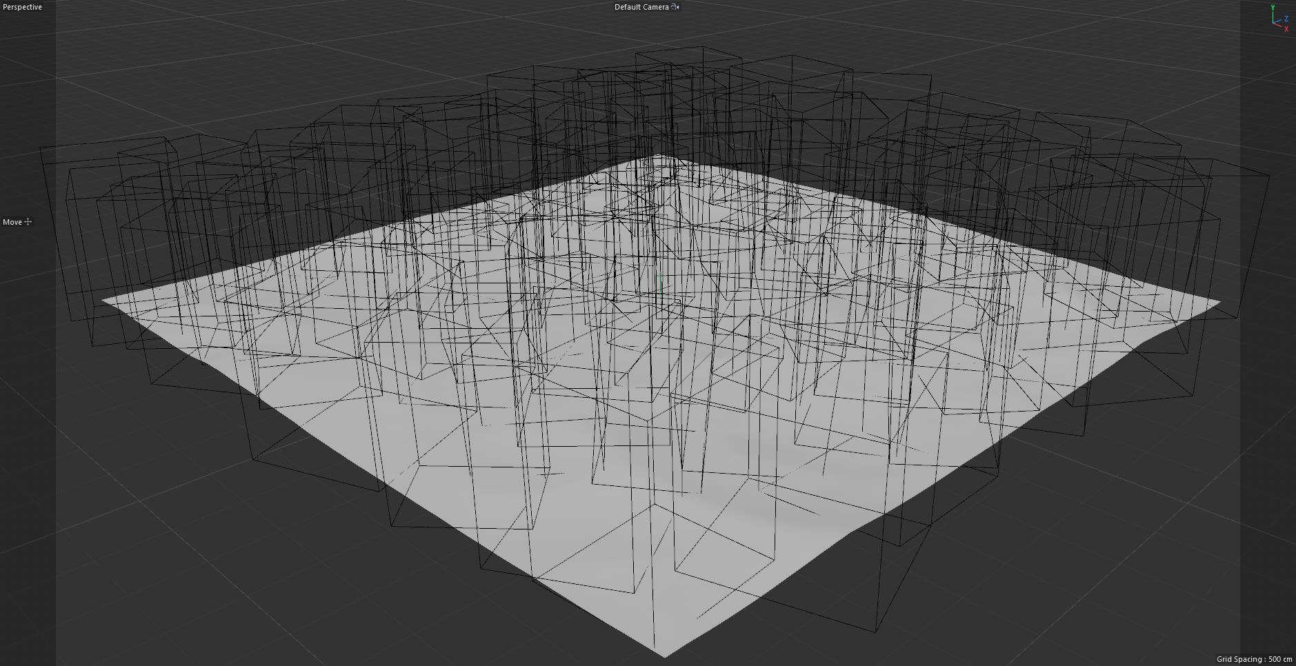
Display mode – Selects how to display scattered instances in the viewport. Affects viewport performance. Available display modes are:
None – Instances are not displayed at all.
Dot – Each instance is displayed as a single dot.
Box – Each instance is displayed as a solid box.
Wire box – Each instance is displayed as a wire box.
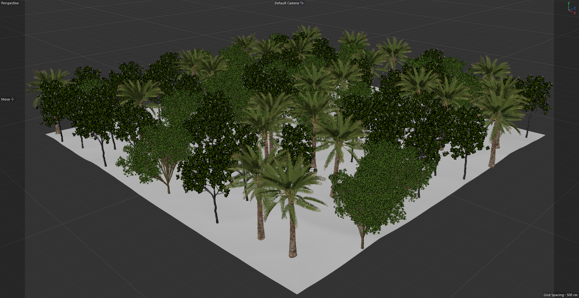
Full – Each instance is displayed as the full mesh.
Max instances – Maximum number of scattered instances being displayed in the viewport. When this limit gets exceeded, some instances are randomly hidden. If increasing this number would display more instances, the label is colored.
Immediate updates – Forces re-computation of the scattering.


Spline scattering
This tab is only available when the Scattering mode is set to "1D - On splines" in the Config tab.
Spacing – Sets spacing between scattered instances measured in world units.
Jitter – Randomly jitters every instance along the spline. The value means how much of the Spacing (half on each side) can be used to jitter around the original position of each instance, e.g. 200% means that every instance jitters by up to the entire Spacing on the left and the entire Spacing on the right.
Offset – Moves all scattered instances along the spline. The value means by how much of the Spacing the instances shall move, e.g. 100% moves the first instance by entire Spacing so that it appears instead of the second one, the second one instead of the third one, etc.
Follow spline – Controls how scattered instances get oriented along the spline. Using the default 100% value, instances follow the spline and are oriented along the local tangent direction. For 0%, instance orientations are unchanged.

Scattering instances on existing Scatter objects
It is possible to scatter objects onto another Chaos Scatter object within your scene. Chaos Scatter objects are supported for use as Distribute on objects.
Example: Scatter object used as Distribute on surface


Chaos Scatter Shaders
Edge Trimming shader
The Edge Trimming shader allows you to trim scattered instances consisting of multiple mesh elements so that they stay within the boundaries of the distribute-on objects.
To learn more about it, please visit the following:
The Edge Trimming shader is located under the plugins > ChaosScatter category when loading a shader.

Surface color
Mode – Allows setting the mode for the Surface color shader
- Custom shader – Uses a custom shader as the surface color. You can then randomize this map's hue and gamma using the built-in controls.
- Surface diffuse/base shader – Automatically uses the distribute-on object's diffuse/base shader.
Hue random – Controls randomization of the resulting color hue. The value specifies the maximal distance from the original hue (in the range of 0-100%), where 0% disables hue randomization and 100% applies maximal hue randomization.
Gamma random – Adds additional randomization of mid-tones (gamma) to the result (in a range of 0-100%), where 0% disables randomization and 100% applies maximal reasonable gamma randomization.
The Surface Color Shader automatically takes the diffuse color of the Chaos Scatter distribute-on object and passes it to the instances which are scattered on it. The shader itself takes only the distribute-on diffuse color, but it can be applied to any material property of the scattered instance (e.g. roughness, opacity, self-illumination, or any other).
To learn more, see: How to use Chaos Scatter with Corona for Cinema 4D
The Edge Trimming shader is located under the plugins > ChaosScatter category when loading a shader