eThis page provides information on the Voxel Shader component.

Overview


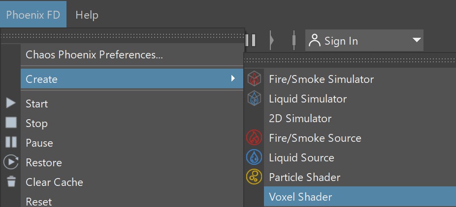
The Voxel Shader node is used to shade Fire/Smoke simulations and meshes in a single Simulator.

Phoenix has multiple rendering modes that can be divided into two types: Volumetric and Surfaces. The volumetric modes are used for fire and smoke. Maya materials can't be used to shade volumetrics because they don't have surfaces. Instead their shading is described in the FireSmoke Color and Smoke Opacity rollouts. Unlike the volumetric modes, in surface modes the Simulator behaves just as any regular geometry - Maya materials can be applied to the Simulator and there is no need for a dedicated shader.


Rendering


Voxel Grid - Specifies the Phoenix Simulator or V-Ray Volume Grid from where the voxel grid data will be read.

Render Presets – Opens a menu for loading and saving different presets. The following options are available:

  • Default Phoenix Render Settings;
  • Fire/Smoke from FumeFX;
  • Fire/Smoke .vdb from Houdini;
  • Liquid .vdb from Houdini;
  • Fire/Smoke .vdb from Maya Fluids.

Step % | rendstep – Specifies the ray marching step of the camera rays as a percentage of the cell size. As the renderer traces rays through the Simulator, this value controls how often to read information from the Grid. If this value is more than 100, some cells will start getting skipped and artifacts may appear. Usually you don't need to lower this below 90%, unless you use render curves or texture maps for the Fire or Smoke opacity or color - in these cases you might need to lower the step in order to capture the details which are smaller than a voxel, otherwise these details will either be skipped or will render very noisy. However, decreasing the step will make the render slower.

Shadow Step %rendshadstep – Specifies the ray marching step of the rays used to evaluate the lighting (shadow rays) as a percentage of the Cell Size. Usually, this value can be higher than Step %, as generally shadows will not need so much detail. Increasing the Shadow Step % will also speed up rendering performance, particularly with dome and area lights.

Border Fade (units) | borderFade – Makes the content near the Grid's boundaries more transparent to prevent sharp edges from being rendered. This parameter controls how far from the boundaries the transparent effect should start, in Scene Units.

Sampler Type | sampler – Determines the blending method between adjacent grid voxels. Used to balance between rendering speed and quality.

Box – Displays voxels as cubes. There is no blending between neighbor voxels. This is the fastest mode.
Linear – Linear blending occurs between neighbor voxels to smooth out the fluid's look. Sometimes this mode may unveil the grid-like structure of the fluid. Up to 20-30% faster than the Spherical option.
Spherical – Uses special weight-based sampling for the smoothest looking fluid. With increasing resolution, the visual advantage of this method over the Linear method becomes less noticeable.

Motion Blur Multiplier | mbmult – Specifies a multiplier that affects the strength of the motion blur. This value can be a negative number. 

Volumetric Motion Blur | volMoblurMethod – Specifies the type of Motion Blur that will be used.

Ray-traced – The default Volumetric Motion Blur method.
Grid-based – This method could be used instead of the default Ray-traced method in cases when you need more visible motion blur streaks, especially with faster moving fluids. The method requires a pre-pass and uses more memory.

Note that the Grid-based method only affects the Volumetric, Volumetric Geometry, and Volumetric Heat Haze Modes and it doesn't apply to Mesh, Ocean Mesh, Cap Mesh, or Isosurface Modes.

Velocity Texture | rendVelTexture – Specifies a custom texture used for motion blur when rendering Fire/Smoke simulations. The colors of the texture represent the velocity direction for each cell, similar to how Vector Displacement textures are evaluated. Every Simulator cell receives a certain color from the texture, treats it as a direction vector and stretches the contents of the Simulator along to produce motion blur. This parameter can be used with a V-Ray User Color texture for motion blur in a single direction (e.g. by setting the color to (0, 1, 0) for motion blur in the +Z axis), or any other Maya texture applied as a 3D projection. The texture overrides the Velocity grid channel even if available in the cache files. Note that the Y and Z components of the velocity vectors are flipped - they are sampled respectively from the Blue and Green color values of the texture.  


Surface


Surface Channel | sarg – Specifies the channel that will define the surface of the fluid. It is used for solid rendering and displacement.

Texture - the values of a custom texture will define the fluid surface.
Liquid/Temperature - the Liquid/Temperature channel will define the fluid surface. Temperature is typically in the range 0-1 for Liquid simulations and 600-2000 for Fire/Smoke simulations.
Smoke - the Smoke channel will define the fluid surface. Smoke is typically in the range of 0-1 for Fire/Smoke simulations.
Speed - the Speed channel will define the fluid surface. Speed channel output has to be enabled for this to work. Speed is calculated as the length of the velocity vector for each voxel.  
Fuel - the Fuel channel will define the fluid surface. Fuel channel output has to be enabled for this to work.
Viscosity - the Viscosity channel will define the fluid surface. Viscosity channel output has to be enabled for this to work.  

Texture | rendEffectTex – If the Surface Channel is set to Texture, this slot specifies the texture. For more information on texture mapping in Phoenix, please check the Texture mapping, moving textures with fire/smoke/liquid, and TexUVW page.

Isosurface Level | rendSurfLevel_x, rendSurfLevel_t, rendSurfLevel_s, rendSurfLevel_v, rendSurfLevel_f –  Allows you to specify a threshold value for the generation of the geometry surface. Grid cells below this value will be ignored. By default, the Isosurface Level is set to 0.5 and should only be modified if there is flickering in the generated geometry.

Invert Volume | rendInvertNorm – By default the values above the surface level are considered internal. When enabled, this option swaps the inside and outside.


Render Cutter


Use Render Cutter | rendUseGizmo – When enabled, rendering will occur only inside the selected geometric object's volume. If Fire Lights are enabled, only those inside the cutter will be rendered. Note that the Cutter Geometry will not work when the Render as Geometry option is enabled.

Set Selected Object as Render Cutter - When a polygon mesh and a Phoenix Simulator are selected, the selected mesh will be used as the Render Cutter for the geometry generated by the Simulator. 

Invert Cutter | rendInvGizmo – When enabled, rendering will occur only outside of the render cutter. This is not the same as a cutter with inverted geometry because any rays that do not intersect the cutter will be shaded as well.

Render as Geometry | geommode – This method requires V-Ray. It produces the same result as the default Volumetric option by using procedural geometry made up from multiple transparent layers. Used when rendering Fire/Smoke for exporting deep images and Render Elements such as Normals, Velocity, Multi Matte, etc. which would not be available in default Volumetric mode. Note that enabling this option would slow down rendering.


Displacement


Displacement Amount | rendDisplrendDisplEnbl – Specifies a displacement strength multiplier.

Texture | rendDisplFine – Specifies the displacement map. Depending on the Type option selected, a monochrome map or a color map could be required. If a colored map is specified when a monochrome map is needed, the strength of the displacement is determined by the total intensity of the color. If a monochrome map is specified when a vector map is needed, the entire displacement will point in a single direction. For more information on texture mapping in Phoenix, please check the Texture mapping, moving textures with fire/smoke/liquid, and TexUVW page.

The difference between Surface driven and Vector displacement is that vector displacement can produce more complicated surfaces. For example, a wave texture in Vector mode produces waves that have a convex back side and a concave front side, in contrast with the symmetrical forms produced by Surface driven displacement.

Type | rendDispltSurf – Specifies the displacement technique.

Gradient driven – Requires a monochrome texture map. The displacement amount is the texture's brightness at each point. Each point of the fluid is shifted along the gradient of the Surface channel. This means that each point in space could have a different displacement direction. This method is suitable for smoke and fire.
Surface driven – Requires a monochrome texture map. The displacement amount is the texture's brightness at each point. Each point of the fluid is shifted along the normal of the point's projection on the isosurface of the fluid's Surface channel. The texture is also sampled at the projection point. Unlike the Gradient driven displacement, this ensures that all points above or below the fluid surface will be displaced in the same direction, and so displacing Fire/Smoke simulations produces better results that are more similar to displaced solid geometry surfaces. However, the Surface driven method is slower than Gradient driven.
Vector – Requires a colored vector texture map (with negative and positive values). The point is shifted by the texture color, interpreted as a 3D vector. This displacement mode is intended to be used with the Phoenix Ocean Texture but can be used with any other vector displacement texture.
Advection – Requires a colored 0.0-based vector texture map (with negative and positive values). A very similar method to Vector, but does not produce grainy structures for fire and smoke. Can be combined with the Phoenix Grid Texture, with its Channel set to Velocity, to produce render-time gridless advection.


Volumetric


Heat Haze | rendHeatHaze – Traces the ray changing direction according to the gradient of the Surface channel. A value of 1 corresponds approximately to the normal heat haze in the air caused by the temperature. If smoke or another channel is selected as the source, a larger value might be necessary to achieve a visible result. A value of 0 produces no heat haze.

Volumetric Material ID | materialID – Material ID color for the MateralID Render Element.

Volumetric ZDepth | volZDepth – Used to generate a Z-depth Render Element.

Disable – Disables generating the render element.
Standard Element - The Z-depth of the Phoenix volumes will be written to the V-Ray Z-Depth Render Element.
Phoenix Element - The Z-depth of the Phoenix volumes will be written to a new Phoenix "zDepth" Render Element.

Volumetric Normals | volNormals – Used to generate a render element with volumetric normals. Since V-Ray does not allow volumetrics to write into the normals RE, the result will be written to a separate RE.

Disable – Disables generating the render element.
Phoenix Element – The volumetric normals of the Phoenix volumes will be written to a new "PhoenixFD_normals" render element.


Fire


This rollout controls the emissive (fire) color of the Volumetric Shader and the light emitted by the Simulator. From here you can control the color and intensity of the emission, and also you can gradually transition between a physically correct and artistic look of the fire.

Based on | emSource – Specifies the source channel that will be rendered as fire. By default, the Temperature channel is used.

  • Disabled - the emission component of the shader will be disabled
  • Temperature
  • Smoke
  • Speed
  • Fuel
  • Texture - the emission will be based on the texture map specified in the Texture parameter
  • RGB

Texture | emTexture – If Based on is set to Texture, this slot specifies the texture from which fire is rendered. This slot can also specify a texture to be used with the Modulate option. For more information on texture mapping in Phoenix, please check the Texture mapping, moving textures with fire/smoke/liquid, and TexUVW page.

Modulate | emModulate – Enabling this option multiplies the Based on channel by the map in the Texture slot. This is only effective when Based on is not set to Texture.

Reset to Defaults – Resets the rollout settings to their default values.

Fire Opacity Mode | emIgnoreAlpha – While smoke has its own opacity in the Smoke Opacity rollout, the Fire opacity can be determined in either one of the following three ways:

Use Smoke Opacity – Fire will use the same opacity that is set to the smoke in the Smoke Opacity rollout. This means the fire will not be visible in cells where there is no smoke.
Fully Visible – Fire will always render as if it has full opacity, but will not produce alpha. This way fire will be visible even in cells that have no opacity. This mode is intended for use with Phoenix simulations, such as simulations with sources that emit Temperature but do not emit Smoke. During rendering, Phoenix internally composes the fire with the scene using additive blending, and such blending must be used when compositing fire manually. However, this mode is not suitable for compositing fire mixed with smoke.
Use Own Opacity – Custom varying opacity for the fire using the Opacity diagram and/or using a texture.

Physically Based | emBlackBody – Transitions between an artistic look of the fire (when set to 0) and a realistic physically-based Intensity (when set to 1). The realistic mode multiplies the fire intensity by the Black Body Radiation model, which gives strong brightness to the hot parts of the fire.

Opacity Texture Mode | emAlphaSrc –  Available only when the Fire Opacity Mode is set to Use Own Opacity.

Don't Use Opacity Texture – The Fire Opacity will be based entirely on the Color and Opacity Curve below.
Multiply Opacity By Texture – The Color and Opacity Curve will be multiplied by the specified texture to produce the final Fire Opacity.
Fire Opacity From Texture – The Fire Opacity will be based entirely on the specified texture - the Color and Opacity Curve below will be ignored.

Opacity Texture | emAlphaTexture – If Opacity Texture Mode is set to Multiply Opacity By Texture or Fire Opacity From Texture, this slot specifies the texture used to modulate the Fire Opacity. For more information on texture mapping in Phoenix, please check the Texture mapping, moving textures with fire/smoke/liquid, and TexUVW page.

Fire Multiplier | emMult – General multiplier for the fire color's intensity.

Opacity Multiplier | emAlphaMult – Multiplier for the fire's own opacity when it is detached from the Smoke Opacity. Used only when the Opacity Mode is set to Use Own Opacity.


Color Gradient and Intensity/Opacity Curve


When the Based on option is set to a Grid channel, this grid simulation data must be remapped to render data. The sim data channel is laid out horizontally along the X axis in the color gradient and intensity/opacity curve. The color gradient remaps the sim data from the Based on channel to fire color. The curve remaps the sim data to fire opacity (in Use Own Opacity mode), or to fire intensity otherwise. The opacity/intensity is mapped vertically on the Y axis.

The channel data range is highlighted in the curve with a light-blue range. You can find out more about Phoenix Grid Channel Ranges here.

Color | emRampColor_t, emRampColor_s, emRampColor_v, emRampColor_f – Controls the color of the light as a function of the selected channel's value. This color is multiplied by the Fire Multiplier to achieve the final value that will be used. The selected channel's data range will be highlighted in light blue.

Intensity | epower_t, epower_s, epower_v, epower_f – Visible when the Fire Opacity Mode is set to Use Smoke Opacity or Fully Visible. The luminance of the emitted light is determined by the function represented in the diagram control. Along the X axis is the value of the selected Based on source channel (Temperature, Fuel, etc.). The color of the light is set by the gradient control above. The selected channel's data range will be highlighted in light-blue.

Opacity | epower_t, epower_s, epower_v, epower_f – Visible only when the Fire Opacity Mode is set to Use Own Opacity. The opacity of the emitted light is determined by the function represented in the diagram control. Along the X axis is the value of the selected Based on source channel (Temperature, Fuel, etc.).

You can use the following controls in the color gradients and diagrams:

Double click – Creates a new point or changes an existing one.
Left button drag over a point
– Moves the point. If several points were selected beforehand, they will move the same amount.
Left button drag over several points
– Selects several points.
Middle button drag over the background
– Drags the visible area. If the Shift key is pressed, scales the diagram in the corresponding direction.
Mouse wheel
– Zooms in/out.
Mouse wheel near the borders of the control – Zooms in/out only along X or only along Y.
Right-click
– Displays a drop-down menu where you can add a point, edit or delete a selected point, and fit the entire diagram or gradient into the view. If multiple points are selected, they can be edited simultaneously. Multiple selected points can also be scaled and flipped with the Scale Selection option as seen below.


Fire Lights


The Fire Lights rollout controls how the fire casts light on the other scene objects as well as on the Phoenix Simulator's own Smoke.

When using Global Illumination (GI), the fire will illuminate everything (scene objects as well as the Simulator's own Smoke) automatically but the rendering will take longer. Turning on Create Fire Lights simulates GI by placing light sources in the bright parts of the fire, which gives similar results and renders much faster. The color and power of these lights are adjusted automatically but can be overridden.

 The smoke illumination caused by the Simulator's own fire can be controlled with the Self Shadowing option. If enabled, the smoke will obstruct the path of light from the fire, creating a much more realistic look but decreasing rendering performance. To gain back the rendering speed, set Self Shadowing to Grid-based and decrease the Light Grid Resolution (%) parameter to reduce the number of generated lights.

All Fire Lights options are ignored when rendering with V-Ray GPU. Enable Global Illumination from the V-Ray Settings if you need the Smoke and/or the scene to be illuminated by the fire.

Create Fire Lights | emLightsCountEnbl – When enabled, allows the fire to shine on smoke and on surrounding objects in the scene even without using Global Illumination (GI). With GI, the fire will automatically illuminate the other scene objects and the Simulator's own smoke, but the rendering will take quite long. Enabling Create Fire Lights simulates GI by placing light sources in the bright parts of the fire, which produces similar results and renders much faster. 

If Create Fire Lights is enabled when rendering using GI, additional light sources will still be created by the fire at render time. You should disable Create Fire Lights if you want to let the GI naturally illuminate the scene.

Using Generate GI and Receive GI options from the V-Ray Object Properties will be ignored while Create Fire Lights is enabled.

Light Power on Self | emLightsPowerOnSelfMult – Controls the light intensity over the simulator's own smoke. This will not change the intensity and color of the fire itself; only the illumination over the smoke is affected.

Light Power on Scene | emLightsPowerMult – Controls the light intensity over all scene objects except the Phoenix Simulator itself.

Self Shadowing | emLightsSelfShadow – Enables self-shadowing of the smoke from the fire's light. If enabled, the smoke will obstruct the path of light from the fire, creating a much more realistic look but decreasing rendering performance. To gain back the rendering speed, set Self-Shadowing to Grid-based and decrease the Light Grid Resolution (%) parameter to reduce the number of generated lights.

None – Smoke will not obstruct the light propagation and will be brightly lit.
Ray-traced – The simulator's smoke will be illuminated by the fire's light sources using precise but slow ray-tracing. Note that the fire lights always illuminate the rest of the scene using ray-tracing. This mode is physically correct and takes into account non-transparent obstacles inside the Phoenix volume, but requires intense computation and can take considerable time to render and clear the noise from the image.
Grid-based – The self-illumination of the smoke will be calculated separately from the light that the simulator casts on the scene using an approximate fast formula. While Ray-traced may produce noise, this mode has no such effect - the resulting illumination on the smoke is always smooth. However, any obstacles inside the Phoenix volume are ignored by this mode and will not cast shadows on the smoke from the simulator's own light. The Light Grid Resolution (%) parameter can be used to lower the resolution of the light grid and further speed up the illumination process. Reducing the grid will generally produce smoother self-illumination. Note that using Grid-based self-shadowing requires additional memory, so beware of high RAM usage with high resolution grids or many copied or instanced volumes.

Light Grid Resolution (%) | emLightsGrid – Specifies the resolution of the light grid as a percentage of the fire grid's resolution. Perfect illumination from fire could be achieved by placing a light in each fire cell, but this could take a tremendous amount of time to render and such accuracy is usually not necessary to approximate the fire's illumination convincingly. In order to speed up rendering, a separate light grid is created internally which can have a lower resolution than the fire grid, and this light grid is populated with one Omni light per each cell. The lower resolution (and thus fewer lights) speeds up rendering at the expense of some illumination detail, which might not always be visible anyway. At a value of 100, the light grid has the same resolution as the fire grid. The smaller the Light Resolution is, the smoother the illumination becomes and the faster the rendering is. However, at very low values the fire might not blend well with the light it casts on the smoke.

Light Cut-off | emLightsCutoff – This is a V-Ray specific control that works the same as the VRayLight cutoff parameter. This parameter specifies a threshold for the light intensity, below which the light will not be computed. This can be useful to limit the effect of the Phoenix light to some distance around the simulator. Larger values cut away more light; lower values make the light range larger. At 0.0, the light will be calculated for all surfaces, but the rendering could slow down significantly. Note that you need to reduce this parameter is sharp circular banding artifacts become visible.

Decay Type | emLightsDecayType – Controls how quickly the simulator's emissive light fades when travelling away from the fire light sources:

None – The light does not fade at all unless obstructed.
Inverse – The light intensity fades with the inverse of the distance. E.g. at a distance of 5 units, the intensity will be 1/5th of the intensity of the emitter.
Inverse Square – The light fades with the inverse square of the traveled distance. This is physically correct light propagation. For example, at a distance of 5 units, the intensity will be 1/25th of the intensity of the emitter.

The parameters below control how many rays have to be traced in order to calculate the lighting. The larger the ray count, the better looking the result will be, but it will render more slowly. For general explanation of how light sampling works, see the V-Ray Image Sampler page.

Direct Subdivs | emLightsSubdivs – Sampling control for direct lighting. This parameter controls the number of the rays traced from the shaded point toward the fire in order to find the optical passability between them. The number of rays cast towards the fire is the square of this value. If the value is zero, a special case is used and all emissive lights are sampled. This could be quite slow when having a big number of emissive lights.

Caustic Subdivs | emLightsCaustSubdivs – Sampling control for Caustic effects. Similar to GI subdivisions, but used when caustics are calculated.

Create Lights Even If Not Renderable | emLightsPersist – When enabled, forces the simulator to emit light over the scene even if rendering the simulator itself is disabled. Can be used for compositing when the simulator is rendered in a separate pass.


Smoke Color


This rollout controls the Diffuse color of the Volumetric Shader. The Smoke Color can be a uniform color, a mixture of colors dragged by the simulation (RGB), a function of any physical channel, or sampled from a texture. It is also affected by lights and shadows cast by objects in the scene.

The diffuse color needs external light to become visible if GI is enabled in the V-Ray Render Settings in Maya.

 Based on | difSource – Specifies the source channel that will be used to determine the smoke color. By default, a uniform simple color set by the Constant Color option is used. This could also be a texture map, or read from the cache files - in that case the corresponding grid channel must be enabled from the Output rollout before the simulation is run.

  • Disabled - the smoke color will not be rendered.
  • Temperature - the smoke color will be based on the values of the Temperature cache channel and can be remapped using the color gradient.
  • Smoke - the smoke color will be based on the values of the Smoke cache channel and can be remapped using the color gradient.
  • Speed - the smoke color will be based on the values of the Speed cache channel and can be remapped using the color gradient.
  • Texture - the smoke color will be based on the values of a texture map plugged into the Texture slot.
  • Constant Color - the smoke color will be the same for the entire volume and will be taken from the Constant Color box.
  • RGB - the smoke will be based on the values of the RGB channel.
  • Fuel - the smoke will be based on the values of the Fuel channel and can be remapped using the color gradient.

Texture | difTexture – If Based on is set to Texture, this slot specifies which texture to use. For more information on texture mapping in Phoenix, please check the Texture mapping, moving textures with fire/smoke/liquid, and TexUVW page.

Modulate | difModulate – When Based on is not set to Texture, the color is multiplied by the texture in the Texture slot.

Reset to Defaults  – Resets the settings to their default values.

Constant color | difSimpleColor – If Based on is set to Constant Color, this color is used.

Scattering | difScattering – Controls how the light rays are scattered inside the volume.

Ray-traced (GI only) – Enables physically accurate scattering of light rays. This mode produces the most realistic results but it's the slowest to render. It requires V-Ray with enabled Global Illumination, otherwise the rendered result would be the same as if the option is Disabled. The Diffuse Multiplier does not affect the rendering in this mode. Use this mode when you want to render bright clouds.
Disabled – Disables scattering. The Diffuse Multiplier value can be used to correct the brightness because without light scattering the volume would generally render darker.
Approximate – Uses an approximate formula which is faster than Ray-Traced scattering and produces good-looking results. Brighter areas of the volume would transfer light farther than dark areas.
Approximate+Shadows – Same as Approximate, but also affects the strength of shadows over the scene geometry.

Phase Function  | phase_function – Controls the direction in which the light will scatter inside the volume. Negative values correspond to backward scattering, which mimics a volume made up of solid particles and will produce denser and more detailed looks. Negative values are more suitable for smoke or dust effects. Positive values correspond to forward scattering, which mimics a volume made up of water droplets where light will scatter more. Positive values are suitable for highly scattering volumes such as clouds. The default value of 0 will scatter the light in all directions and create an even and diffuse look.

Note that values very close to 1.0 or -1.0 will produce very directional scattering that will be invisible from most angles, so such values are not recommended. When rendering with a Phase Function different than 0 and Volume Light Cache is enabled the rendered result will be brighter. The Phase Function is ignored when the scattering is set to Approximate or Approximate+Shadows.

Optimize Anisotropic Scattering anisotropic_scattering_optimization – [V-Ray specific] When enabled it can greatly reduce the render times for highly scattering volumes such as clouds. Due to certain assumptions made for the optimizations, the optimized render result might produce different results compared to the exact brute-force anisotropic scattering. The option is ignored when the scattering is set to Approximate or Approximate+Shadows.

Scatter Depth | difScatterDepth – Specifies the maximum depth of the GI rays.

Volume Light Cache | difLightCache – Enables light caching for each voxel of the grid, which speeds up bucket rendering considerably when the voxel size of the grid is significantly larger than the rendering pixel. If the grid resolution is large enough compared to the rendering resolution, disabling this option will speed up rendering.

  1. This option refers to the internal Phoenix FD Light Cache, which is not related to the V-Ray Light Cache.
  2. When using V-Ray Progressive Rendering, this option might slow down rendering startup or the overall render speed. 
  3. This feature might produce artifacts when the smoke is very dense.
  4. This feature might produce artifacts when objects cast shadows through the smoke.
  5. Rendering multiple copies or instances of the simulator node with this option turned on might lead to slow-downs.
  6. This option will consume additional memory, so beware of high RAM usage when rendering very large cache files or a large number of copied or instanced volumes.
  7. When rendering with Render as Geometry enabled any of these Render Elements: [ Shadow ], [ Raw Shadow ], [ Global Illumination ], [ Raw Global Illumination ] , the Volume Light Cache will require additional memory to produce the correct result. Please be aware that these Render Elements (and most other V-Ray Render Elements except for [ Atmosphere ] and [ Self-Illumination ] ) are not supported when Render as Geometry is disabled.
  8. This option is ignored when using V-Ray GPU. It is a CPU-only feature that helps speed up Bucket rendering.

Light Cache Speedup | difLightCacheSR – [Valid only when Volume Light Cache is enabled] The higher this option is set, the faster the rendering will be, but the lower the quality of the Volume Light Cache. You can increase this parameter and gain render speed as long as you don't start getting dark cubic grid artifacts on the smoke.

Own Light Scatter Mult | difOwnLightsBoost – [Valid only when Scattering is set to Approximate  or Approximate+Shadows] This multiplier determines how far the light travels through the volumetric, based on the distance from the emissive light itself.

External Scatter Mult | difExtLightsBoost – [Valid only when Scattering is set to Approximate  or Approximate+Shadows] This multiplier determines how far the light from all external light sources travels through the volumetric. Both Scatter Boost parameters don't alter the visual density of the smoke to the camera, and only apply to the illumination.

Diffuse Multiplier | difMult – A general multiplier for the diffuse color. It is ignored when the Scattering mode is set to Ray-traced (GI only).

Shadow Strength | difShadowStrength – A multiplier for the opacity of the shadow that the volumetric casts on other objects.

Color gradient – When the Based on option is set to a grid channel, this color gradient remaps grid simulation data to render smoke color. The sim data channel is laid out horizontally along the X axis in the color gradient.

The channel data range is highlighted in the curve with a light-blue range. You can find out more about Phoenix Grid Channel Ranges here.


Smoke Opacity


This dialog controls the Transparency component of the Volumetric Shader.

The Smoke Opacity settings below will affect the rendering of Fire if the Fire Opacity Mode in the Fire rollout is set to Use Smoke Opacity.

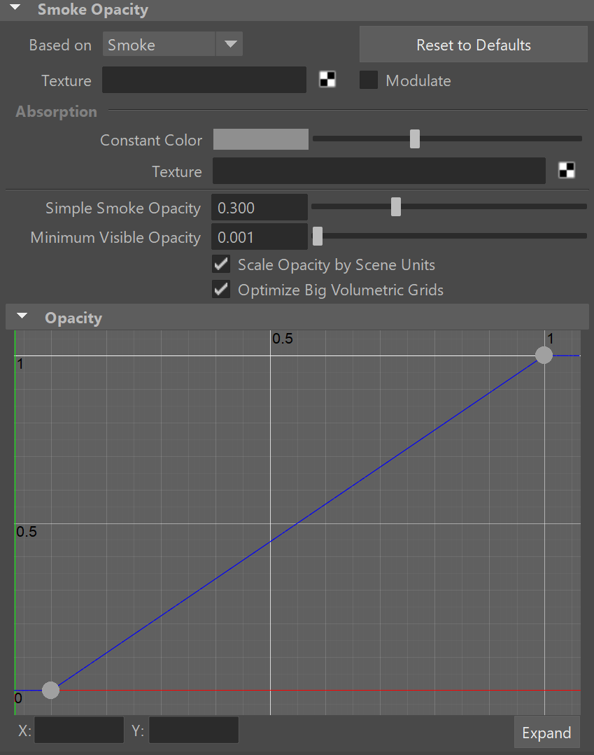
Based on | trSource – Allows you to select how the smoke opacity is computed. By default, this is set to the Simple Smoke option. It could also be based on a texture map, or read from the cache files - in that case, the corresponding grid channel must be enabled from the Output rollout before the simulation is run.

  • Simple Smoke – Use directly the Smoke channel as opacity, without remapping it through the Opacity Curve. The opacity is controlled only by the Simple Smoke Opacity. If you want to get similar results to Simple Smoke mode using the Opacity Curve in Smoke mode, create a straight line in the Opacity Curve from coordinates [0; 0] to [1; Simple Smoke Opacity], and then bend the middle of the curve upwards. As Simple Smoke Opacity increases, the curve needs to be bent more strongly.

  • Temperature – Use the temperature channel and remap it through the Opacity Curve to get the rendered opacity. Can be used to produce smoke without needing the smoke channel in the simulation.

  • Smoke – Use the smoke channel and remap it through the Opacity Curve to get the rendered opacity.

  • Speed – Use the magnitude of the velocity channel and remap it through the Opacity Curve to get the rendered opacity.

  • Texture – Use a texture map plugged in the Texture slot as opacity, without remapping it through the Opacity Curve.

  • Fuel – Use the fuel channel and remap it through the Opacity Curve to get the rendered opacity.

Texture | trTexture – If the Based on parameter is set to Texture, or if Modulate is enabled, this slot specifies the texture to be used. For more information on texture mapping in Phoenix, please check the Texture mapping, moving textures with fire/smoke/liquid, and TexUVW page.

Modulate | trModulate – When enabled and Based on is not set to Texture, the Based on channel is multiplied by the texture in the Texture slot.

Reset to Defaults – Resets the settings to their default values.

Absorption  – Controls the color of the volumetric shadows and the tint for the objects seen through the volume. Brighter colors make the volume more transparent, while darker colors make it more opaque (denser).

  • Constant Color – Specifies the color that will be used for the absorption effect.

  • Texture – When a texture is connected in the slot the absorption constant color will be ignored and the texture color will be used instead. For more information on texture mapping in Phoenix, please check the Texture mapping, moving textures with fire/smoke/liquid, and TexUVW page.

Simple Smoke Opacity | trSimpleSmFactor – When the Based on parameter is set to Simple smoke, this value is used as opacity multiplier.

Minimum Visible Opacity | trSkipShLevel – If the opacity of a voxel is below this specified value, the voxel will not be shaded at all. Increase this value to speed up rendering. Decrease it if parts of the smoke are too transparent and start disappearing in the render.

Scale Opacity by Scene Units | trAlphaUnitScale – When enabled, the opacity per unit length will remain constant when changing the Grid resolution. Therefore, the larger the unit scale is, the denser the smoke will appear in renders and vice versa. This option is Off for imported Field3D and OpenVDB cache files. Note that this option also affects Fire in Use Own Opacity mode. It does not take effect if there is no loaded cache file.

When Scale Opacity by Scene Units is disabled, Phoenix caches simulated at higher grid resolution will appear more opaque than the same simulation at a lower resolution.

Optimize Big Volumetric Grids | trOptimizeVolumetrics – Helps render scenes with caches above 15 Million cells faster. This option requires additional grid memory during rendering, so you could disable it if you don't have enough RAM. If using Progressive rendering or there are a lot of Phoenix Simulators in the scene, and you want your render to start without a pre-pass, you might want to disable this option. 

This option is ignored when rendering with V-Ray GPU.

Opacity Curve – When the Based on option is set to a grid channel, this curve remaps grid simulation data to smoke opacity. The sim data channel is laid out horizontally along the X axis in the opacity curve. The opacity is mapped vertically on the Y axis.

The channel data range is highlighted in the curve with a light-blue range. You can find out more about Phoenix Grid Channel Ranges here.