The instructions on this page guide you through the process of creating a collapsing building effect using Chaos Phoenix 4, V-Ray Next and Thinking Particles 6.
Overview
This is an Advanced Level tutorial. The workflow for setting up the shot, and the Phoenix settings involved in the simulation are explained in detail. However, creating a production quality shot of a similar nature may require some tweaks to the lighting, materials and/or the Phoenix simulation. An understanding of thinkingParticles is beneficial but not required.
This tutorial demonstrates how to work with Thinking Particles in tandem with Phoenix. The fragments coming from the Thinking Particles simulation are used as Source Geometry for the Phoenix Fire/Smoke simulation. Each fractured piece is represented as its own shape for a realistic interaction between the geometry and the smoke. The fractured geometry is used to drive the simulation by injecting velocity into the grid. Finally, all scene elements are cached to disk and rendered with V-Ray.
This simulation requires thinkingParticles 6, Phoenix 4 Official Release and V-Ray Next Official Release for 3ds Max 2015 at least. You can download official Phoenix and V-Ray from https://download.chaos.com. If you notice a major difference between the results shown here and the behavior of your setup, please reach us using the Support Form.
The Download button below provides you with an archive containing the start and end scenes.
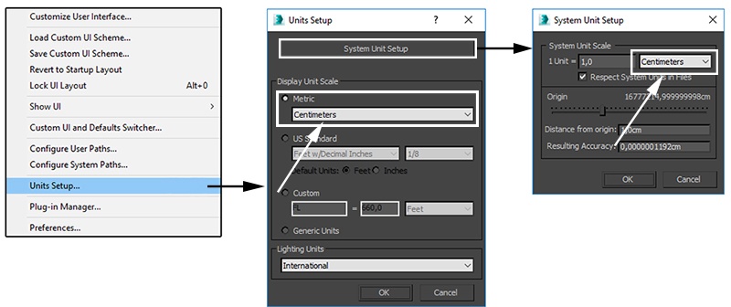
Units Setup
Scale is crucial for the behavior of any simulation. The real-world size of the Simulator in units is important for the simulation dynamics. Large-scale simulations appear to move more slowly, while mid-to-small scale simulations have lots of vigorous movement. When you create your Simulator, you must check the Grid rollout where the real-world extents of the Simulator are shown. If the size of the Simulator in the scene cannot be changed, you can cheat the solver into working as if the scale is larger or smaller by changing the Scene Scale option in the Grid rollout.
The Phoenix solver is not affected by how you choose to view the Display Unit Scale - it is just a matter of convenience.
As the focus of this tutorial is a large-scale ship simulation, setting the units to Meters seems like a reasonable choice.
Go to Customize → Units Setup and set Display Unit Scale to Metric Meters.
Also, set the System Units such that 1 Unit equals 1 Meter.
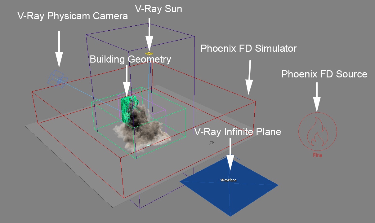
Scene Layout
The final scene consists of the following elements:
- Pre-fractured Building geometry used for the Thinking Particles simulation.
- Thinking Particles simulation for the Building geometry.
- Sphere with animated transform used to activate the fractured pieces (named sphere_activateFracturedPieces in the start scene).
- Phoenix Fire/Smoke Simulator.
- Phoenix Fire/Smoke Source emitting Smoke from the pieces of the building.
- V-Ray Sun&Sky setup for lighting.
- V-Ray Physical Camera for rendering.
- V-Ray Plane only used at rendertime.
- Cars and Street Lights geometry for additional detail to the scene.
Thinking Particles Simulation
The next couple of sections contain instructions for caching the Thinking Particles simulation. The setup is not discussed in-depth, only provided as a starting point for the Phoenix simulation.
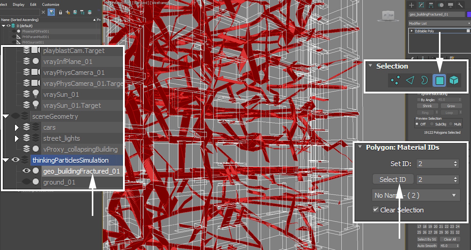
The fractured pieces of the building are placed on the particles of the Thinking Particles simulation.
The faces where the fractures occur have a Polygon ID of 2 assigned to them. This Polygon ID is later used in the Phoenix Source to limit the emission of smoke.
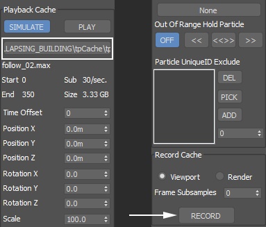
To cache the Thinking Particles simulation to disk, select the thinkingParticlesNode in the Scene Explorer and open the Properties window.
Select Master Dynamic...
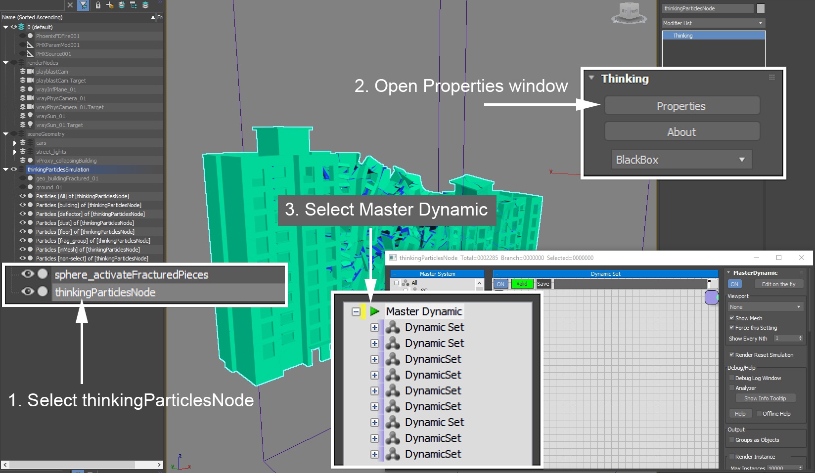
Under the Playback Cache section, select the Output Path for the cache files and hit Record.
That is all. Once the Thinking Particles simulation is cached, we can proceed with the Phoenix simulation.
Phoenix Simulation
Go to Modify Panel → Create → Geometry → PhoenixFD → FireSmokeSim.
The exact position of the Phoenix Simulator in the scene is (X, Y, Z): (17, 2, 0 ).
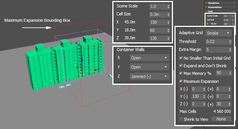
Open the Grid rollout and set the following values:
- Cell Size: 0.3m.
- Size (X, Y, Z): (150, 60, 130) - we keep the Simulator size smaller than the entire building during the R&D process. For the final simulation, the Size is set such that the entire building is confined in grid.
- Container Walls → Wall Z: Jammed (-) - the bottom of the simulator is jammed (closed) so that the smoke does not leave the bounds of the simulation as it travels down.
- Adaptive Grid: Smoke - the Adaptive Grid algorithm allows the bounding box of the simulation to dynamically expand on-demand. With a Threshold of 0.02, the Simulator will expand when the Cells near the corners of the simulation bounding box reach a Smoke value of 0.02 or greater.
- Extra Margin: 5 - the Extra Margin option is useful when the Adaptive Grid algorithm is unable to expand fast enough to accommodate for quick movement in the simulation (e.g. an explosion). The Extra Margin parameter attempts to remedy this by expanding the grid preemptively with the specified number of voxels on each side.
- Enable Expand and Don't Shrink - this way the Adaptive grid will not contract back when there is very thin smoke at the borders of the grid.
- Enable Max Expansion: X: (0, 0), Y: (130, 0), Z: (0, 30) - to save memory and simulation time by limiting the Maximum Size of the simulation grid.
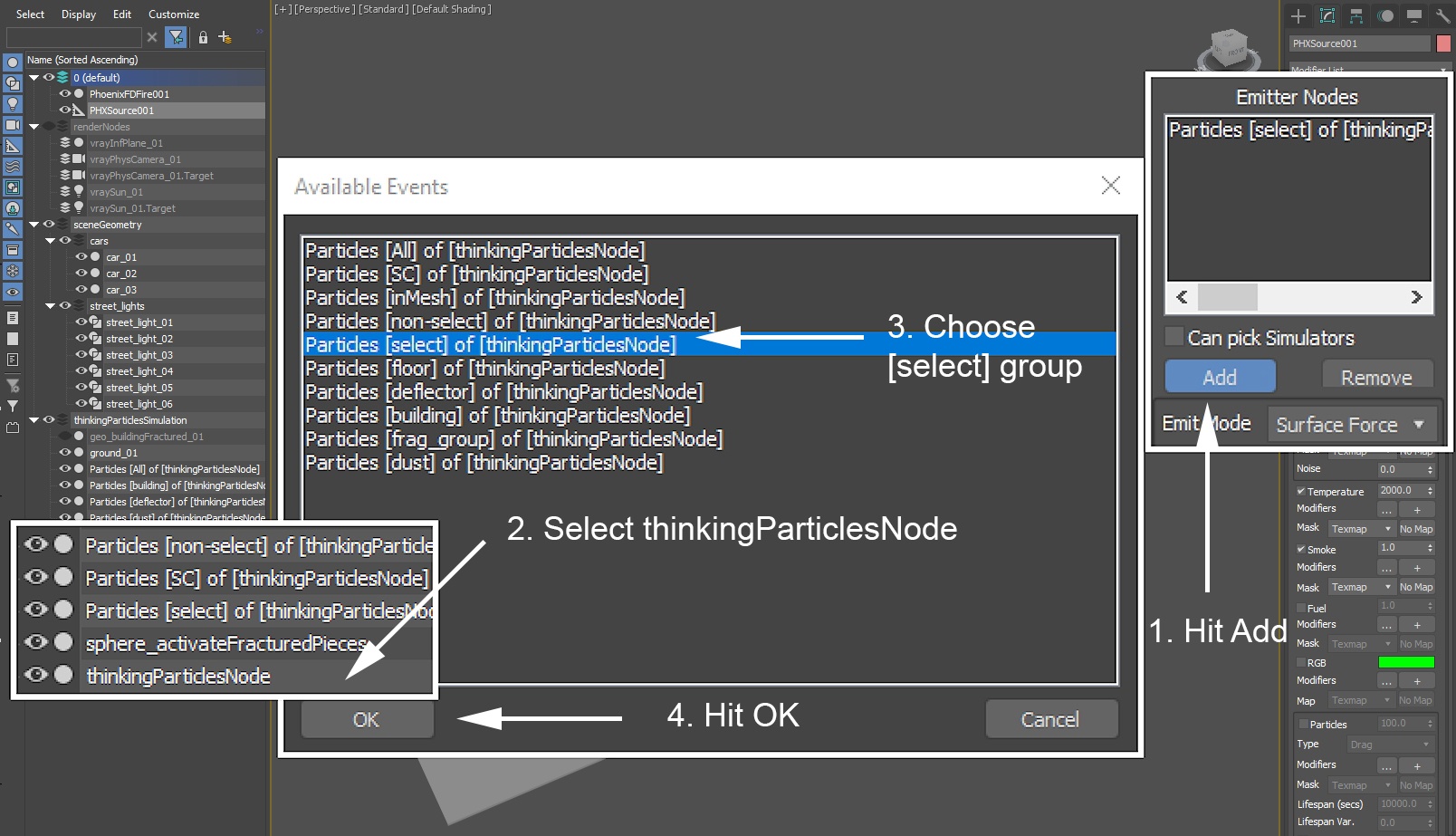
Add a Phoenix Fire/Smoke Source: Modify Panel → Create → Helpers → PhoenixFD → PHXSource.
Click the Add button to choose geometry to emit from and select the thinkParticlesNode entry in the Scene Explorer.
A pop-up window will appear, listing all Particle Groups of the Thinking Particles simulation.
Choose the Particles [ select ] group and hit OK.
Select the Phoenix Fire/Smoke simulator and open the Scene Interaction rollout.
Use the Add button to include the ground_01 and sphere_activateFracturedPieces objects into the Exclude List of the simulation so they are ignored during the simulation. The ground geometry is unnecessary because we use the bottom wall of the Simulator for the same purpose. The sphere_activateFracturedPieces, on the other hand, overlaps the entire building geometry - if not excluded from the simulation, it will behave as a solid body and all smoke inside of its volume will be removed.
The Scene Interaction set can be used in two modes:
- Include List - only those objects present in the list below will be used during the Phoenix simulation. Sources, Source Geometry, Solid/Non-Solid Objects, Forces, etc. need to be included or will otherwise be ignored.
- Exclude List - all scene objects will be used for the Phoenix simulation except those in the list below.

Set the Phoenix Simulator → Simulation rollout → Start Frame to 5 so it matches the start frame of the Thinking Particles simulation.
The Timeline checkbox needs to be disabled for the numerical field to become un-templated. By default, the Timeline checkbox specifies the Start Frame as the first frame on the Timeline.

To the right is a Preview Animation of the simulation in its current state.
We can see that the Smoke is rising up instead of falling down - this is caused by the Temperature channel which is generated by the Fire/Smoke Source by default.
To enable the GPU Preview as seen on the video to the right, select the Phoenix Simulator → Preview rollout → GPU Preview → Enable in Viewport.
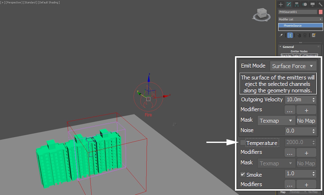
Select the Phoenix Fire/Smoke Source and disable the emission of Temperature.
By default, Temperature is emitted with a value of 2000 Kelvins (~1700 Celsius, or ~3100 Fahrenheit). Because hot air rises up, the Smoke is going straight up upon emission.
Disabling Temperature will cause the Smoke to stand still unless acted upon (by a Force, a Solid Object or Simulator → Dynamics rollout → Smoke Buoyancy).
If you'd like the Smoke to travel downward (akin to dry ice), either reduce the emitted Temperature below 300K, or disable it altogether and set the Simulator → Dynamics rollout → Smoke Buoyancy to a value lower than 0.
Since we disabled the emission of Temperature from the Fire/Smoke Source, writing the Temperature Grid Channel to the cache files is unnecessary.
Disable Phoenix Simulator → Output rollout → Temperature to save some disk space.

To the right is a Preview Animation of the simulation in its current state.
As expected, the Smoke is standing still upon emission after disabling Temperature.
You may be wondering why the Smoke is not interacting with the building geometry...
By default, the Thinking Particles selected as emission geometry in the Phoenix Source are represented as Non-Solid geometry. Non-Solid geometry can be used as a Source but does not affect the simulation in any way.
Select the following Thinking Particle Particle Groups in the Scene Explorer:
- Particles [ building ]...
- Particles [ non-select ]...
- Particles [ select ]...
With the mouse cursor over the Viewport, Right-Mouse-Button click and select 'Chaos Phoenix Properties...' from the menu.
Under the Phoenix Properties dialog, enable Solid Object.

Select the Phoenix Source and enable Motion Velocity.
When Motion Velocity is enabled for a Solid Object, geometry moving through the simulation will add velocity in the same direction as the object's trajectory.
When Motion Velocity is disabled for a Solid Object, the geometry will still collide with the simulation but the Smoke will not attempt to follow it along its trajectory.

To the right is a Preview Animation of the simulation in its current state.
As the building is collapsing, the falling pieces accelerate the smoke towards the ground. As the smoke reaches the bottom of the simulation grid, it starts rolling to the side.
Select the Phoenix Source and set the Outgoing Velocity parameter to 50.

To the right is a Preview Animation of the simulation in its current state.
Increasing the Outgoing Velocity makes the smoke thicker and allows it to roll further once it reaches the ground.
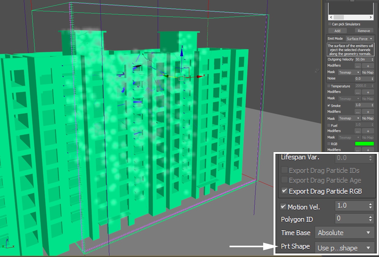
Select the Phoenix Source and set the Prt Shape parameter to Use Particle Shape.
By default, each piece is represented as a single point with a radius of one voxel. This is faster to compute and good enough for most purposes.
For maximum realism, we use the actual shape of the pieces as source geometry by telling the solves to use the objects attached to the particles. The faces of each piece will now emit smoke with an Outgoing Velocity of 50.
This will significantly increase the amount of smoke in the simulation.
To the right is a Preview Animation of the simulation in its current state.
Every single face of every single piece is emitting smoke, all at the same time. In real life, when a building collapses, only the areas around the cracks will produce dust. As mentioned in the beginning of this walk-through, the inside faces of the fractured pieces are separated from the rest of the building with a specific Polygon ID. The Phoenix Source can use this ID to only emit from those faces which share it.
Select the Phoenix Source and set the Polygon ID parameter to 2.

To the right is a Preview Animation of the simulation in its current state.
As expected, only the inside faces emit smoke now.
However, we need to resolve another problem - the pieces emit smoke during the entire simulation. Instead, they should be emitting only while falling towards the ground.
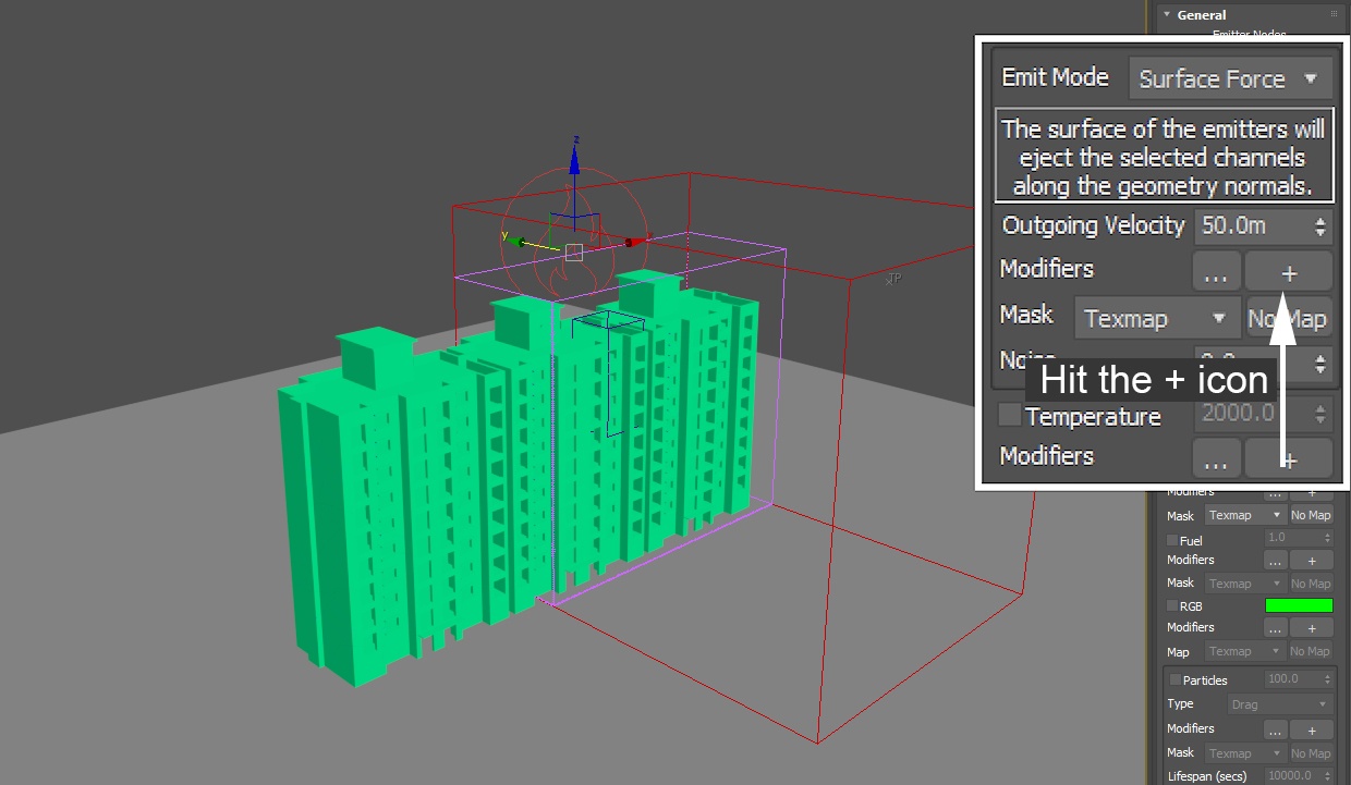
We can use a Discharge Modifier for the Phoenix Source to tell the solver to only generate smoke from those pieces which are accelerating towards the ground, in the negative Z direction.
Select the Phoenix Source and hit the '+' icon under the Outgoing Velocity parameter.
This will connect a Discharge Modifier to the Source.
For more information on Discharge Modifiers, please refer to the Phoenix Documentation.
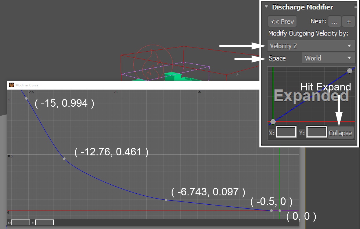
Under the Discharge Modifier options, set the following:
- Modify Outgoing Velocity by: Velocity Z.
- Space: World.
- Hit the Expand button and add the following points to the ramp: (-15, 0.994) , (-12.76, 0.461) , (-6.743, 0.97) , (-0.5, 0) , (0, 0)
The Discharge Modifier acts as a multiplier for the Outgoing Velocity parameter. The Y-axis values of the ramp will be used as the multiplier.
So, for instance, if the Velocity of a piece travelling straight towards the ground is -15 ( it's negative 15 because it's going down - if it was travelling upwards, the Velocity Z value would be positive ) on Frame 10, the Outgoing Velocity for that specific piece would be multiplied by 0.994. If another piece was travelling at -0.5, its Outgoing Velocity would be multiplied by 0.
The building height is ~36 meters, and it took ~121 frames for the building to completely fall down to the ground. 121 / 30 = 4.0333s. Therefore, the estimated velocity is -36 meters / 4.0333 sec = -8.92 meter / sec. The curve should be drawn based on this value.
To the right is a Preview Animation of the simulation in its current state.
The static pieces no longer emit smoke due to the Discharge Modifier applied to the Outgoing Velocity.
Select the Phoenix Source and set the Smoke amount to 5.
The difference between increasing the Smoke and Outgoing Velocity parameters is in the way the content is generated.
You could increase the Outgoing Velocity to achieve a similar result. However, the Outgoing Velocity parameter will not only pump more smoke into the simulation, but also more velocity. This will disturb the emission and cause the falling pieces to emit with an unnatural strength while on their way to the ground.

To the right is a Preview Animation of the simulation in its current state.
In the next step we modify the color of the emitted smoke.
Select the Phoenix Source and enable RGB emission.
Plug a Noise texture into the Map slot for the RGB channel.
The RGB channel is dragged along the Velocity field in the exact same manner as the Smoke channel. For more information on the RGB channel and working with it, please take a look at the dedicated Simulation RGB Workflows tutorial.

The following settings are dialed in for the Noise texture:
- Tiling X/Y/Z: 100 / 100 / 100
- Noise Type: Fractal
- Size: 50
- Threshold High/Low: 1 / 0.3
- Color #1: RGB [ 56, 42, 28 ]
- Color #2: RGB [ 224, 206, 192 ]
Those settings are completely arbitrary and will only affect the color of the smoke. Feel free to tweak them based on your own artistic judgement.

Select the Phoenix Simulator → Output rollout and enable the output of the RGB Grid Channel. While here, also enable the output of Velocity.
If you'd like to perform a Resimulation using Wavelet Turbulence, enable the Wavelet Grid Channel output.
Any channel that you intend to use after the simulation is complete needs to be cached to disk. For example:
- Velocity is required at render time for Motion Blur
- Temperature is usually used at render time to generate Fire
- Wavelet is used for Wavelet turbulence when performing a Re-simulation

Under the Phoenix Simulator → Rendering → Volumetric Options button → Smoke Color rollout, set Based on: RGB.
This option also works for the Viewport so we should be able to see the smoke colored based on the RGB channel.

Open the Phoenix Simulator → Grid rollout and set the following:
- Cell Size: 0.18.
- Size XYZ: (400, 100, 200).
- Adaptive Grid → Max Expansion: X: (350, 350), Y: (450, 450), Z: (0, 40).
The exact position of the Simulator is XYZ: (0, 2, 0).
Those are the final Grid settings for the simulation.

To the right is a Preview Animation of the simulation in its current state.
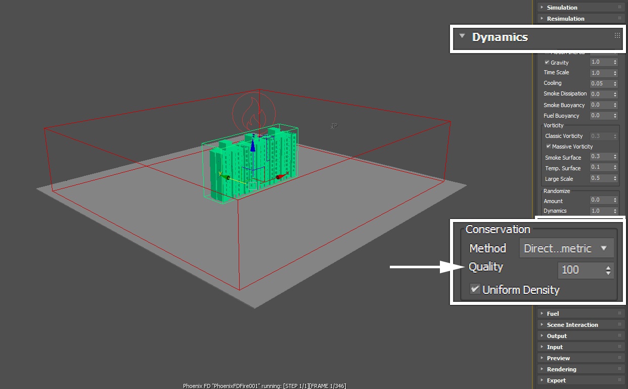
Note that the behavior of the smoke is more akin to bubbling rather than rolling out. To achieve a realistic flow in this situation, the swirling motion of the smoke needs to be boosted. This can be achieved by increasing the Conservation Quality parameter under the Dynamics rollout. Please refer to the following example images in the documentation.
Select the Phoenix Simulator → Dynamics rollout and set the Conservation Quality to 100.
This change will boost the swirling motion of the smoke, allowing it roll out further.
To the right is a Preview Animation of the simulation in its current state.
At this point the simulation is complete. You may skip straight to the Rendering section, or work through the Re-simulation section in case you'd like to add some additional detail for a close-up shot.
Resimulation
Open the Phoenix SImulator → Resimulation rollout and enable Grid Resimulation.
Note that when you enable Resimulation, Phoenix will try to read the cache files for preview and rendering from the Resimulation Output Path, instead of the 'regular' Output. Don't be alarmed if the Viewport goes blank - you can always go back to the original cache files by disabling the resimulation.
Set the Amp.Resolution to 0.5. This parameter is used to increase the resolution of the grid for the Resimulation process only (just like the Cell Size in the Grid rollout controls the resolution of the simulator).
Set Amp. Method to Interpolate - the interpolation can sharpen the existing simulation without pushing the details too much.
Hit Simulator → Simulation rollout → Start to begin the re-simulation.
If you'd like to perform a Re-simulation using Wavelet Turbulence, set the Amp.Method either to Wavelet Fast or Wavelet Nice. The Wavelet Strength will then control how strongly the fine detail from the generated Wavelet grid channel will affect the Resimulation.
In this example, we don't use Wavelet Turbulence because the wispy, fine detail generated by it breaks the illusion of a large-scale simulation.

To the right is a Preview Animation of the simulation in its current state.
At this point we're done with the Phoenix simulation. In the final Rendering section of this tutorial, we focus on wrapping up our work and generating the final image.
Rendering
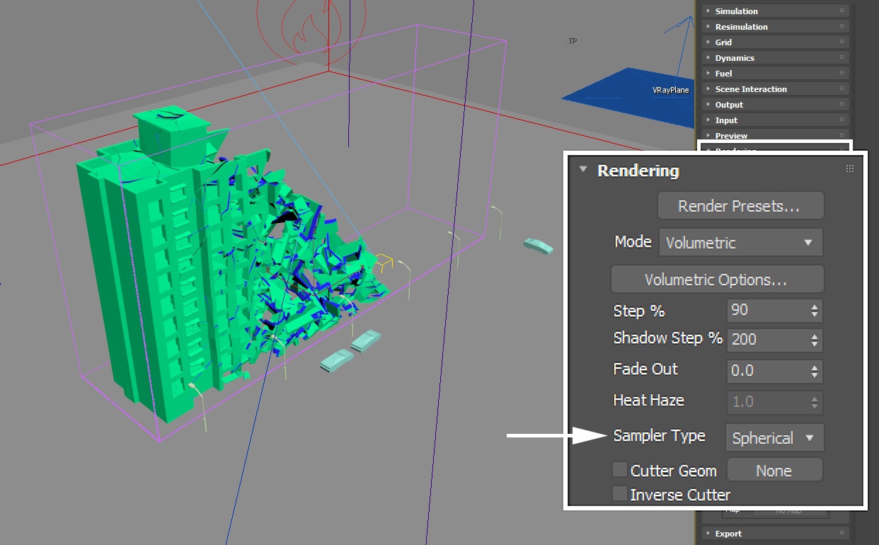
Optionally, you may set the Phoenix Simulator → Rendering rollout → Sampler Type to Spherical to avoid grid artifacts if your simulation looks too sharp.
For this particular scene, it won't make a tremendous difference but depending on your setup, this may be a good way to smooth-out the smoke.
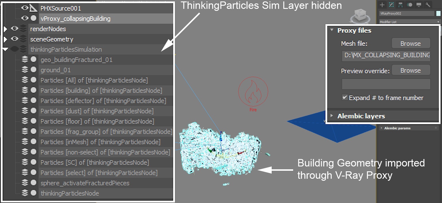
Finally, we export the Thinking Particles simulation as a mesh so we can render the TP cache directly without worrying about licensing or asset transfers if distributed rendering.
Select the thinkingParticlesNode in the Scene Explorer and open the Properties Window.
Under the Master Dynamic tree, the final DynamicSet entry contains an Alembic Export node.

Select the 'All' particle group and hit the Add button so its added to the Export Particle Groups list.
Click the Select Record File and specify a disk path for the cache files to be saved.
Set the Export Mode to Object per Group so the geometry itself is cached instead of the particles its instanced on top of.
Hit the Export button and wait for the caching process to complete.

You may now hide the entire thinkingParticlesSimulation layer in the Layer Explorer.
Go to Modify Panel → Create → Geometry → VRay drop-down and add a V-Ray Proxy.
Point the Proxy to the exported Alembic file.
The final image is rendered to the V-Ray Frame Buffer, with the Color Corrections → Exposure set to:
- Exposure: 1.04
- Highlight Burn: 0.92
- Contrast: 0.10
Set the White Balance → Temperature to 6900.
