This page guides you through the process of creating rogue ocean waves using the Massive Wave Force option in Phoenix.
Overview
This is an Advanced Level tutorial. The workflow for setting up the shot, and the Phoenix settings involved in the simulation are explained in detail. However, it's recommended that you have at least basic knowleage in lighting, materials, and the Phoenix simulation.
This tutorial explores how to create large ocean waves (up to 50 meters tall) with Phoenix.
It presents simulated waves only, without any additional geometry to push the water or any rigging involved. We take advantage of the Phoenix option "Massive Wave Force" that allows the force to affect the entire volume of the simulator to produce high waves.
In addition, a galleon ship is added to the scene to use it as an active body interacting with the waves.
This simulation requires Phoenix 4.41.02 Nightly, Build from 19 Oct 2021 and V-Ray 5 Update 1.3 for 3ds Max 2018 at least. You can download nightlies from https://nightlies.chaos.com or get the latest official Phoenix and V-Ray from https://download.chaos.com. If you notice a major difference between the results shown here and the behavior of your setup, please reach us using the Support Form.
To download project files: Download Project Files
Want to follow along but don’t have a license?: Download Free Trial
Units Setup
Scale is crucial for the behavior of any simulation. The real-world size of the Simulator in units is important for the simulation dynamics.
Large-scale simulations appear to move slower, while mid-to-small scale simulations have lots of vigorous movements.
When you create your Simulator, check the Grid rollout where the real-world sizes of the Simulator are shown. If the size of the Simulator in the scene cannot be changed, you can trick the solver into working as if the scale is larger or smaller by changing the Scene Scale option in the Grid rollout.
The Phoenix solver is not affected by how you choose to view the Display Unit Scale — it is just a matter of convenience. Setting the units to Meters is a reasonable choice for this setup.
Go to Customize → Units Setup and set Display Unit Scale to Metric Meters. Also, set the System Units so that 1 Unit equals 1 Meter.

Scene Layout
The final scene consists of the following elements:
- A Phoenix Liquid Source;
- A Phoenix Liquid Simulator;
- Three Particle Shaders for the Foam, Splash and Mist particles respectively;
- A V-Ray Physical camera;
- V-Ray Light Dome for lighting;
A Box geometry used in the Liquid Source for the foam emission;
A V-Ray Plane used as an infinite ground surface - sometimes the V-Ray Plane might cause flickering at the ocean border so consider using a very large regular plane geometry, placed below the liquid simulator instead.
- A Wave Force to drive waves from water;
- An ActiveBodies helper for Active Bodies simulation.

A close-up for the final scene contains the following elements:
- A Ship geometry;
- A Ship_clone geometry. Note that when the Ship geometry is added to the Active Bodies list, Phoenix generates a Ship_clone geometry automatically and sets the original Ship geometry to display as a Bounding Box;
- A Ship_clone.CenterOfMass helper is also created by Phoenix automatically.
Phoenix takes the position of the ship geometry's pivot point to create a Center of Mass helper. If you use a custom ship object, you can adjust the position of your ship's pivot point before you add it to the Active Bodies list. If you don't, you can still adjust the position of the center of the mass helper afterwards. Check the Active Bodies Guide for more details.

Besides the VRayCam_Final for the final rendering, we also create two more cameras for scene development.
- The Camera_Top_RnD is looking from top to bottom and is used for generating a preview for PhoenixOceanTex.
- The VRayCam_RnD is placed in the view where it is easier to observe the simulation results during the development stage.

Scene Setup
Set the Time Configuration > Animation Length to 500, so that the Time Slider goes from 0 to 500.

This tutorial consists of many steps to follow. To keep it concise, let's focus only on the Phoenix related steps and feel free to use the camera and light settings in the provided sample scene.
For your reference, below you can find the light and camera settings.
Camera Setting for VRayCam_Final
Add a VRayPhysicalCamera from Command Panel → Cameras → V-Ray. The exact position of the Camera is XYZ: [ -446.0, 187.0, 84.0 ].
The Focus Distance is set to 439.5.
The exact position of the Camera Target is XYZ: [ -361.0, 351.0, 121.0 ].
Aperture → Film speed is set to 15.0.
Aperture → F-Number is set to 1.4.
Aperture → Shutter Speed is set to 30.0.
Color & Exposure → White Balance is set to Neutral.
Enable both the Depth of field and Motion blur.
In the Bokeh effects tab, the Blades option is enabled and set to 7, with a Rotation of 15. Center bias is set to 1.0.
From frame 150 to frame 500, we have animated both the camera and camera target, so it appears that the sky is moving instead of being static. The camera animation makes the shot more appealing to watch.
The other two cameras: Camera_Top_RnD and VRayCam_RnD are only for scene development, not for rendering. So we don't show their settings in detail here.

Lighting
Press on the Cosmos icon in the V-Ray toolbar. In the HDRIs section → Day → choose Day 035. Press the green arrow to Import the HDR map. Chaos Cosmos generates a VRayLight in the scene with the HDR map plugged in the Texture slot.
The exact position of the V-Ray Light is XYZ: [-425.0, 910.0, 0.0].
Set the VRayBitmap map's Horiz. rotation to 150.0.
Decrease both Overall multiplier and Render multiplier to 0.2.
Starting with V-Ray 5, the VRayHDRI map is renamed to VRayBitmap.

Anatomy of Large Waves
The image here is the final render in this tutorial. The wave is about 50 meters in height. The image shows the typical features of which a plunging wave comprises.
When a wave forms and breaks, we can see the lip of the wave. There are shoulders at the two sides of the lip. The lip forms a curvy pocket (or a tube shape), creating a space for a surfer to pass through. The wave collapses in the end and it generates lots of splashes and foam called "whitewater".
- Lip is the top or crest of the wave.
- Shoulders are called the lower parts of the crest, at the right/left sides of the lip.
- The face is steep and moves as a whole (no breaks).
- Tube or Barrel is the hollow part of a breaking wave. It forms an open tube or barrel.
- Whitewater is the foamy part of the wave after it collapses.
Let's go through the steps and see how to build these features.

Timeline
Here are the two stages of the wave's simulation:
- From frame 0 to frame 30, simulate the foam particles.
- Frame 30 is where the Wave Force kicks in, simulating the ocean waves.
In the tutorial, we first focus on the setup for the ocean wave simulation. Then we add the setup for the foam simulation. These two stages together make the complete animation.

Determine Region for the Simulator
The waves we simulate are driven by a Wave force, and the force is controlled by an Ocean Texture map. Since the Phoenix Ocean Texture is an infinite non-cyclic procedural texture, a different region of the texture generates different waves in its form. In this tutorial, ideally, we like to create a single, symmetric and regular size wave. We don't want a distorted or lengthy wave. Therefore, we need to determine which region on the ocean texture fits the requirement. This is a critical step for the whole setup.
Create a Reference Plane
From Create Panel > Standard Primitives, create a Plane in the scene.
Set the Plane's Length to 1635.0 and its Width to 3040.0.
Segments for both Length and Width are set to 1.
The scale of this plane is enormous. It is a much larger region than we need to to simulate one single wave. We use it as a reference to see which region of the ocean texture suits best for our goal.

Set up the Ocean Texture
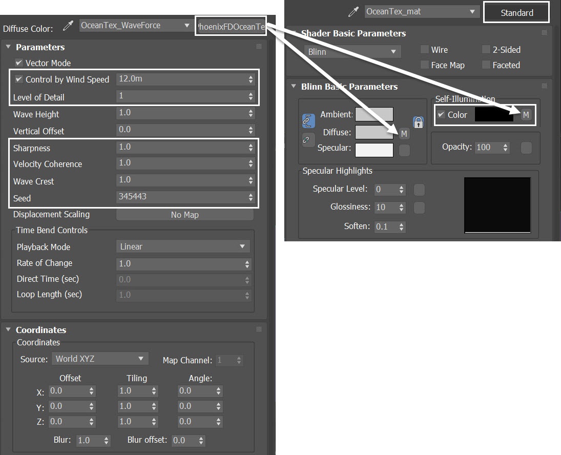
Create a 3ds Max Standard Material and rename it to something suitable, like OceanTex_mat. In the Diffuse and the Self-Illumination slots, plug in a PhoenixFDOceanTex.
Rename the PhoenixFDOceanTex to OceanTex_WaveForce, for example.
Here are the values for the OceanTex_WaveForce parameters set for the tutorial:
- Control by Wind Speed to 12.0m
- Level of Detail to 1
- Sharpness to 1.0
- Velocity Coherence to 1.0
- Wave Crest to 1.0
- Seed to 345443
We set the Level of Detail to 1 in order to get simpler, non-overlapping waves. For the same reason we set the Velocity Coherence to 1.0 - so the waves move in one direction uniformly.
On the other hand, if you intend to create a rough, stormy sea, you can increase the Level of Detail and decrease the Velocity Coherence. This way the waves will become more chaotic.
Apply the OceanTex_mat to the plane we just created.
Here is a rendered animation from Camera-Top-RnD, with 3ds Max default Scanline Renderer. As you can see in the Ocean Texture, the waves are too close. There is no much space to place our camera in between the waves.
Let's adjust the texture tiling of the OceanTex_WaveForce in the next step.
The ship geometry is placed in the center of the scene as a scaling reference. It is around 60 meters in length and 18.5 meters in width.
Adjust Ocean Texture Tiling
Select the OceanTex_WaveForce texture in the Material Editor. In the Coordinates section, set the X Tiling to 0.3 and the Y Tiling to 0.5.

Here is a rendered animation from Camera-Top-RnD, with 3ds Max Scanline Renderer.
Now we have a longer wavelength. There is enough space for us to place a camera between the waves. Besides, the width of the waves became narrower.
Set up the Phoenix Foam Texture
Although, we can tell where the waves might be distributed by looking at the Phoenix Ocean Texture, it is still hard to tell where exactly the wave crests are moving along.
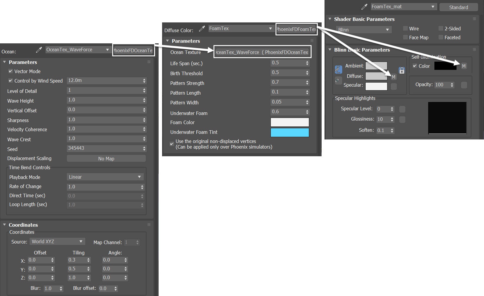
Let's create another 3ds Max Standard Material in the Material Editor. Rename it to FoamTex_mat, for example.
In the Diffuse and Self-Illumination slot, plug in a PhoenixFDFoamTex. Rename the PhoenixFDFoamTex to FoamTex.
For the Ocean Texture slot of the FoamTex, plug in the OceanTex_WaveForce, the same ocean texture we've set up in the previous steps.
The Phoenix Foam Texture can be used in combination with the Ocean Texture to create the effect of foam appearing at the crests of the infinite ocean waves. Therefore, we can use this texture as a guide to see where exactly the waves will be. We can pick up the straighter, shorter waves among them.
Here is a rendered animation from Camera-Top-RnD, with 3ds Max Scanline Renderer.
The white stripes represent waves over the ocean surface. Some are longer or curvier than others. The foam texture also shows us how the crests evolve throughout the animation. Some break up into shorter waves. Some merge into a longer one.
We are looking for the shorter and straighter waves here.
Simulator Region
Now we are able to visualize the waves in motion with the help of a foam texture. Let's determine the exact region for the simulation to take place.
From Create Panel > Standard Primitives, create a Box in the scene. Position the box so that it encloses a single wave.
The exact position of the Box in the example scene is XYZ: [-370.0, 478.0, 0.0].
The exact box size is 582.0, 613.0 and 30.0 for Length, Width and Height respectively. Set its Segs to 1 for all three sides.
Add Edit Poly Modifier. Delete the top and bottom faces of the box.
Add Shell Modifier. Give it some thickness with an Outer Amount of 1.0m.
Now we can use the box as a reference to determine where to place our liquid simulator.

Here is a rendered animation from Camera-Top-RnD, with 3ds Max Scanline Renderer.
Now we are confident enough about where to put the simulator for simulating a simple single wave. Notice that only one or two waves are passing through the square frame.
Alternatively, you can keep your simulator position at the scene of origin. You can try different Seed values in the OceanTex_WaveForce texture until you get the desired waves in the area around XYZ: [0.0, 0.0, 0.0].
In later steps, when seen from top view, we don't expect a one-to-one position-wise match in the simulated waves when compared to this Phoenix Foam Texture as a guide. Since it takes time for the Wave Force to act on the liquid particles, there is a delay in time for the simulated waves.
Liquid Simulation
Based on the reference box we created in the previous step, let's now take care of the liquid simulation. Go to Create Panel > Create > Geometry > PhoenixFD > PhoenixFDLiquid. Create a liquid simulator in the scene.
The exact position of the Simulator in this example scene is XYZ: [-370.0, 478.0, 0.0]. This is the same position as the reference box.
Open the Grid rollout and set the following values:
- Cell Size: 1.953 m
- Size XYZ: [298, 313, 38]
- Container Walls: Open to X, Y and Z
Delete the reference box and the reference plane once the Liquid Simulator is created.

Select the Dynamics rollout of the PhoenixFDLiquid. Enable the Initial Fill Up %. Set the value to 50.0.
This way the simulator will be filled with liquid at the start of the simulation.

Select the Output rollout of the PhoenixFDLiquid. Leave the default values.

Select the Preview rollout of the PhoenixFDLiquid. Enable the Show Mesh option. Disable the Particle Preview option.
As for the Rendering rollout, switch the Mode to Cap Mesh.
In the Mesh Smoothing section, set the Smoothness to 5. Enable the Use Liquid Particles option.
Set the Particle Size to 0.5.

Set up a Wave Force
Go to Create Panel > Create > Helpers > PhoenixFD. Press the WaveForce button and create a WaveForce in the scene.
Plug the OceanTex_WaveForce texture into the Ocean map slot of the WaveForce.
Increase the Fluid Freedom to 1.0.
We use the OceanTex_WaveForce texture that we tweaked in the previous steps. It is ready for us to simulate a single wave in this specific region.
Fluid Freedom balances between the strictness of the Wave Force and the free movement of the liquid. When set to 0 the Wave Force strictly follows the used ocean texture as close as possible. Setting it to 1 allows the liquid to roughly follow the ocean texture while maintaining free liquid behavior.

Now, let's go to Graph Editors/Track View > Curve Editor and set keys to the curve of Strength of the WaveForce, so it can change over time.
Each frame and value are shown in the screenshots.
The reason we keyframe the Strength of the WaveForce is because from frame 0 to frame 30 we want the foam to form a pattern. Then the WaveForce kicks in afterwards.

Here is a table with keyframes for the WaveForce's Strength.
Frame | Value | Tangent type |
|---|---|---|
0 | 0.0 | Stepped |
30 | 25.0 | Stepped |
Initial Simulation
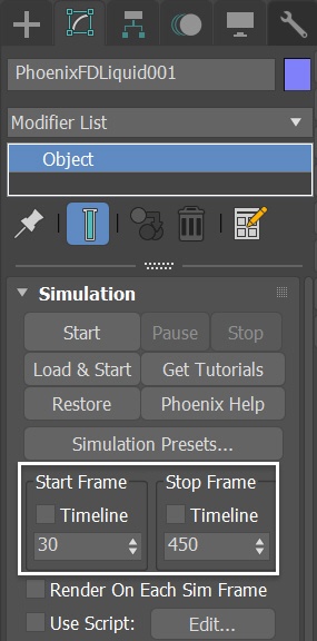
Select the Simulation rollout of the Phoenix Liquid Simulator. Since the Wave Force kicks in at frame 30, set the Start Frame to 30. You don't have to simulate the full length of the animation. Only a sample is enough, so set Stop Frame to 350.
Press the Start button to simulate.
Here is a preview animation of the simulation from Camera-RnD. As you can see, the waves are very subtle, you can barely see them.
With the Liquid Simulator selected, go to the Preview rollout. Enable the Velocity Streamlines option.
By doing so, we can visualize the velocity changes due to the WaveForce acting on the liquid particles. Because the depth of the simulator is not deep enough for the underwater, streaming forms an orbital form, which is critical for tall waves.

Here is a front view animation of the simulation with the Velocity Streamlines option enabled.
Make the Simulator Deeper
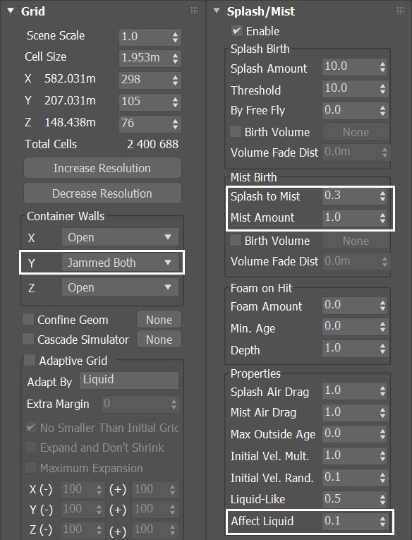
With the Liquid Simulator selected, go to the Grid rollout. Double the value for Z. To save simulation time, we narrow the value for Y. Now the Grid becomes with size XYZ: [298, 105, 76].
With the new Simulation grid settings, run the simulation again.

Here is the preview animation of the simulation after the last step.
We start to see waves. However, the shape of the wave is not what we are after. The waves didn't form a tube.
They look more like spilling type of breaking waves. They collapse too early. The Rate of Change of the ocean texture has to be slower in order to allow liquid particles to form plunging waves.
In the real world, there are basically three types of breaking waves: spilling, plunging and surging waves.
How these waves are formed depends on the shoreline profile. When the ocean floor has a gradual slope, it tends to get spilling waves, while surging waves occur on very steep beaches.
As for computer simulation, the tutorial waves rely purely on the Wave Force. There is no shore geometry in the scene at all and we use Phoenix Ocean Texture to control the Wave Force.
The rate of change of the ocean texture plays the key factor influencing the formation of breaking waves.
Here is a front view preview animation of the simulation with the Velocity Streamlines option enabled. You can see underwater cycle spinning passing through.
Set up Plunging Waves
In the Material Editor, select the OceanTex_WaveForce. Decrease the Rate of Change to 0.8.
With this new setting, run the simulation again.

Here is a preview animation of the simulation. As you can see, we got better shape of breaking waves.
Simulate Splash and Mist particles
With the liquid simulator selected, go to the Splash/Mist rollout.
Enable the Splash/Mist option. When asked if you'd like a Phoenix Particle Shader generated for the Splash particles, select Yes. This automatically sets up the link between the Splash particles group, the Particle Shader, and the Liquid Simulator.
Rename the new particle shader to ParticleShader-Splash. Leave the Shader settings at default, they are adjusted later in the steps.
Run the simulation.

Change Preview Color
To easily spot which particles are which, let's change the color swatches for the different particle types.
Select the PhoenixFDLiquid in the scene and go to its Preview rollout. Set the Splash, Mist, and Foam to Blue (RGB: 0, 0, 255), Red (RGB: 255, 0, 0), and Green (RGB: 0, 255, 0) color respectively.
The exact RGB color for the particle preview is not critical. You can choose other colors as long as they are distinguishable.
Disable the Liquid Preview by unchecking its Show option, so we can track the distribution of the Splash/Mist/Foam particles by their color.
Set Scale Color By to No Scaling for all particle types. This way the particle color will remain constant through the whole simulation.

Let's preview the simulation.
We start to see splash and mist particles. However, the particles are now chipping away the lip of the wave. And there are too much mist particles compared to the splashes.
Moreover, there are some unwanted particles, popping out around the Y-boundaries of the simulator.
With the simulator selected. Set the Y container wall to Jammed Both. This prevents unwanted particles to be generated.
In the Splash/Mist rollout, decrease the Splash to Mist to 0.3. This way fewer splash particles will be converted to mist. Decrease the Mist Amount to 1.0.
In the Properties section, reduce the Affect Liquid to 0.1. This will reduce the amount of liquid particles being converted to splash/mist particles at the tip of the wave crest.
Here is a preview.
We now have splash and mist particles in the wave, while keeping the barrel shape of the plunging waves.
Simulate Air Effects
With the simulator selected, go to the Dynamics rollout. Enable the Simulate Air Effects option.
Simulate Air Effects is an option that turns on the built-in air simulator for the areas in the simulation grid which are not full of liquid. The air velocity is affected by the liquid movement, by Sources, or by fast-moving obstacles inside the Simulator. In turn, the air velocity affects and carries splash, mist and foam particles. The air simulation can dramatically increase the quality of splash and mist effects.

Now, with the Simulate Air Effects option enabled, we get more convincing movements of the splash and the mist particles.
Let's see a front preview of the simulation with the Velocity Streamlines option enabled. You can see clearly the Simulated Air Effects result where the grid has no liquid.
Improving Pattern Formation by Mist Particles
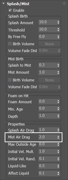
To further fine-tune the mist particles, go to the simulator's Splash/Mist rollout > Properties section and increase the Mist Air Drag to 2.0.
Mist Air Drag controls the air friction of the mist. This value determines not only how fast the speed decreases, but also the influence of the wind. The larger this value, the larger the wind's influence is.
Let's preview the sim animation with the new setting. There are more patterns in the Mist particles formation now.
Adjusting the Splash Particles
We are done adjusting the mist particles. Now let's focus on the splashes.
With the simulator selected, go to the Splash/Mist rollout. Increase the By Free Fly to 0.8.
By Free Fly controls how likely a free falling or flying liquid particle will turn into splash. The main usage of values above 0.0 is in waterfall simulations.
When a wave's amplitude reaches critical level, the wave breaks and that causes large amounts of wave energy to be transformed into turbulent kinetic energy. This process is somewhat similar to a waterfall. That is why we increase the value of this parameter.

When the By Free Fly option is enabled, Phoenix prompts the Chaos Phoenix Warning window. You can disregard the warning on this occasion. Also check the Do not show this message again to avoid this window from showing again.
Let's run the simulation again.

Let's see the new preview - we have more splashes generated when the waves start to break.
Because the Mist particles outnumber the Splashes, they are overlapping. At this stage we focus on the splash settings, so let's turn off the Mist particles in the Preview rollout of the simulator.
Increase Splash Amount
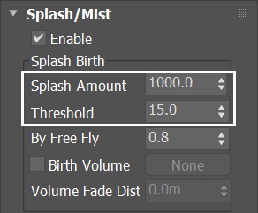
With the simulator selected, go to the Splash/Mist rollout and increase the Splash Amount to 1000.0.
Increase the Threshold to 15.0.
A higher Threshold for the Splash helps forming a pattern in the splash particles, while avoiding smear of the particles.
Now we have enough amount of splashes in the scene. The distribution of the splashes also looks good.
Adding Foam to the Shot
From Create Panel > Standard Primitives, create a Box in the scene.
Set the Box's Length to 613.0, Width to 584.5 and Height to 0.2.
Set the segments for Length, Width and Height to 1.
The exact position of the Box is XYZ: [ -370, 478.0, 74.5 ].
We create a thin box that is placed at water level of the simulator (based on the value of Initial Fill Up %). It is with just enough thickness to brush out Foam particles from it.

Create a Phoenix Liquid Source in the scene by going to Create Panel > Create > Helpers > PhoenixFD > PHXSource.
Set the Emit Mode to Volume Brush.
Press the Add button to choose which geometry to emit and add Box entry to the Scene Explorer.

When you add the Box to the LiquidSrc Emitter Nodes, a Chaos Phoenix window pops out. Choose the Make Non-Solid button to disable the Solid Object option in the Phoenix properties of the box.
Make sure you disable the Solid option of the Phoenix properties of the box. Otherwise, the box blocks the liquid flow as solid objects do.

With the LiquidSrc selected, go to Graph Editors/Track View > Curve Editor and set keys to the curve of the source's Brush Effects %.
We set keyframes for this parameter, so that the source brushes out foam particles only in the very first frame. The frames and values are shown in the screenshot.

Here is a table with keyframes for the LiquidSrc's Brush Effects %.
Frame | Value | Tangent type |
|---|---|---|
0 | 100.0 | Stepped |
1 | 0.0 | Stepped |
For the LiquidSrc:
- Disable the Emit Liquid option.
- Enable the Particles option, set the number to 800000.0. Set the particles Type to Foam.
In order to add some variation to the foam distribution we can use a texture map as a mask.
Set the Mask type to Texmap. Plug a VRayCompTex in the slot. Rename it to Mask_for_foam.
- Plug a Noise texture into the Source A slot. Rename it to Noise_small. Set its X Tiling to 0.3. Set its Size to 10.0; High to 1.0; Low to 0.35; Noise Type to Turbulence. Levels to 5.0.
- Plug another Noise texture into the Source B slot. Rename it to Noise_Big. Set its X Tiling to 0.3. Set its Size to 25.0; High to 1.0; Low to 0.35; Noise Type to Turbulence. Levels to 5.0.
Set the Operator to Add(A+B).
We make the X-tiling smaller, so the texture can form a longer stripe. This is because we usually observe long foam stripes over the surface of the surfing waves.

Select the Foam rollout of the Phoenix Liquid Simulator and enable it. A pop-out window prompts you to create a Particle Shader for the foam, so press YES.
Rename the new Particle Shader to ParticleShader-Foam.

Select the Simulation rollout of the Phoenix Liquid Simulator.
Now we want to simulate the foam particles in the scene, so enable the Timeline option for the Start Frame. And set Stop Frame to 450.
Keep everything in the Simulator's Foam rollout at default. With the liquid source in the scene, press the Start button to simulate.

Now we start to see foam particles distributed over the ocean surface. But some foam particles go out of the surface. They do not adhere to the sea surface well.
Improve Foam Settings
With the Simulator selected, go to the Foam rollout. We want to generate the foam from the Liquid Source only. Reduce the Foam Amount to 0.0.
In the Dynamics section, set the B2B Interaction to a value of 0. Reduce the Rising Speed to 0.3. Decrease the Falling Speed to 30.0.
Set the Surface Lock parameter to 1.0.
In the Patterns section, set the Strength option to 0.1 and Radius to 1.2.

Let's preview again.
Now we tweaked the splash, mist and foam particles. We see the plunging waves taking shape. Let's set up the ship as an active body.
Position the Ship
Since the ship already exists in the Big_Waves_max2017_start scene, all we have to do is move it to the right position.
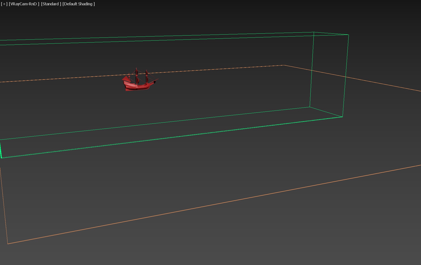
Let's select the Ship geometry in the scene and move it to XYZ: [ -454.0, 636.0, 70.0].
The reason why we move the ship to this position is to avoid direct hit by the plunging wave. It is facing the shoulder of the waves for less impact. You can put it in other places you if you'd like.
With the simulator selected, adjust its Cell Size and XYZ. We increase the grid resolution but make the Y narrower, to save simulation time. Set:
- Cell Size: 1.25 m
- Size XYZ: [466, 80, 119]
The Active Bodies simulation is sensitive to the grid resolution. At this stage, we better set the cell size small enough. If the grid resolution is too low, the boat might sink even if you have set the proper density for it.

From Create Panel > PhoenixFD > Active Bodies, create a ActiveBodies helper in the scene.
Add the Ship geometry to the Active Bodies list.
Adding the ship to the Active Bodies list creates a center of mass gizmo for you automatically. The gizmo's position is based on the ship's pivot position.

With the Ship geometry selected right-click and open the Chaos Phoenix Properties. Use the Closest preset - Ship Hull to set the ship density to 500.0 kg/m3.
We choose the Ship Hull preset because it seems like a reasonable choice for a start-up. We can fine-tune the density later.

Enable the Active Bodies option the Dynamics rollout of the simulator. Link the Active Body Solver to the Phoenix Liquid Simulator.
Run the simulation.

The ship now is too heavy, it sinks in the sea.
With the Ship geometry selected right-click and open the Chaos Phoenix Properties. Set the Specify Density parameter to 250.0 kg/m3.
Let's run the simulation again.

Here's the preview animation.
Foam Around the Ship
To make the shot even more convincing, let's generate foam around the ship. We use the Mask_for_foam_A texture map created in the previous step.
Let's add another VRayCompTex on top of that. Rename the texture to Mask_for_foam_B.
- The Source A slot is for the Mask_for_foam_A map;
- Plug a VRayDistanceTex into the Source B slot;
- Set the Operator to Add(A+B)
For the VRayDistanceTex:
- Set the Distance to 4.0;
- Set the Far Color to black;
- Set the Near Color to white;
- Add the ship geometry in the VRayDistanceTex Objects list.
The Distance parameter determines how wide the foam is scattered around the ship. Increase this value if you want more foam around the ship.
Switch your renderer from the default Scanline Renderer to V-Ray in order to see the VRayDistanceTex in the Material Editor.

If you get confused, here's the shading network in the Slate Material. You can see the connections here.

Final Simulation
For the final simulation, first switch the view to VRayCam_Final.
In order to get a more detailed result we also increase the Grid Resolution by lowering the Cell Size.
Open the Grid rollout and set the following values:
- Cell Size: 1.0 m
- Size XYZ: [ 582, 611, 150]
The exact position of the Simulator in the scene is XYZ: [-370.0, 478.0, 0.0].

Select the Simulation rollout of the Phoenix Liquid Simulator.
This is the final simulation, so we enable the Timeline option for both Start Frame and Stop Frame, to simulate the full length of the animation.
Press the Start button to simulate.

Here is waht the preview animation of the final sim looks like.
Set up Ocean Texture for Displacement
With the PhoenixFDLiquid simulator selected, go to the Rendering rollout and switch the Mode to Ocean Mesh. Set the Off-Screen Margin to 10.0 and increase the Ocean Subdivs to 3.0.
The Off-Screen Margin allows you to extend the ocean further from the borders of the camera view. This way, we avoid unwanted pop-up of the ocean surface when the displacement is applied to the edge of it. Increase this value as a precautionary step.
When it comes to the far areas of the surface, the Ocean Subdivs determines how many vertices are generated for each pixel of the image. Similar to V-Ray subdivisions, the square of the parameter value is used.
For example, if you increase the number of subdivisions twice, the number of vertices grows four times. Increasing the ocean subdivisions will increase the RAM consumption so try to increasen them gradually and don't to set the value too high.
To add details to the ocean surface, enable the Displacement option. Plug a PhoenixFDOceanTex in the Map slot.
Drag and drop it in to the Material Editor as an Instance. (the Copy option creates a copy of this Map - you want to use the same texture in the simulator and in the material editor instead of being forced to deal with 2 separate PhoenixFDOceanTex so make sure to choose the Instance option). Rename the texture to OceanTex_for_displacement.
Here are the values for the OceanTex_for_displacement parameters that we use in this tutorial:
- Control by Wind Speed to 6.0m
- Level of Detail to 12
- Sharpness to 1.0
- Velocity Coherence to 0.2
- Wave Crest to 1.0
- Seed: 345443
Set Coordinates Z Angle to 180.0, so that the direction of the ocean waves are opposite to the direction of displacement.
Velocity Coherence controls the degree of variation in the Wave Direction. When this value is set to 1, all waves move in the same direction, as they do in coastal areas. When set to 0, all waves move in random directions, as they do in the open seas.
The OceanTex_for_displacement and the other ocean texture we used for the WaveForce are two different ocean textures.
The one for the WaveFoce is designed for simple, pure waves that move in one direction, while the the displacement texture is for adding small details to the ocean surface.

Water Material
Let's take a look at the water material now.
Create a V-Ray Material and assign it to the PhoenixFDLiquid Simulator. Set the Diffuse color to black.
Reflect and Refract colors are set to white - it produces a completely transparent material if the Index of Refraction is set to 1 (which is the IOR of clear air). But let's set the IOR to 1.333, which is the physically accurate Index of Refraction of water.
Keep the Max depth to its default value of 8 for both Reflection and Refraction.
To slightly blur the specular highlights produced by the sources of illumination in the scene, reduce the Reflection Glossiness to 0.9.
If you render now, you'd notice that the water is completely transparent and does not look like ocean water.
Instead, let's switch the Translucency to Volumetric. Set the Fog color to RGB : [217, 234, 230] and set the Depth to 300.0.
Set Scatter color to RGB : [53, 146, 125]. Set SSS amount to 0.8. This produces the type of shading expected in a large body of water containing all sorts of particles that interfere with the light rays.
If you trying to achieve a gloomy day render, the subsurface-scattering is not so important, so you can set the Translucency to None to save you some rendering time.

Set up Particle Shaders
We have a Particle Shader for splashes and foam already. For the Mist particles, we have to create a new Particle Shader manually.
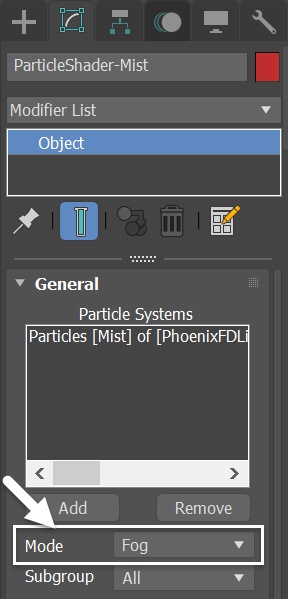
Go to Create Panel > PhoenixFD and press the PHXFoam button to create a new Particle Shader in the scene. Rename it to ParticleShader-Mist.

Press the Add button and pick the Liquid Simulator, then select the Mist particle group.
Set the ParticleShader-Mist mode to Fog.
Here is a test rendering with the default Particle Shader setup. Too much mist is noticeable in the shot. The mist-rich area appears overbright. All the particles look granular, as their size is too big.
Besides, you can see some foam particles offset from the ocean surface at the simulator's borders.
Before you render, be sure to turn on the VRayLight in the scene. The light is turned off with the Scanline Renderer in the early scene development stage.
If the original Ship geometry shows up in the render, go to its Object Properties and disable the Renderable option. The Ship_phx_clone is the only ship we are supposed to render out.

Because we use the Fog mode for the Mist particles, we can skip rendering the Fog with Motion Blur. When we run a test render, a warning message appears. Select "Do not show this message again" and press OK.

Final Adjustment to the Particle Shaders
Adjust the Particle Shaders for foam, splash and Mist.
For the ParticleShader-Foam:
- Set Mode to Points;
- Size Multiplier to 0.3;
- Enable the Flatten At Ocean Borders;
- Enable and set the Light Cache Speedup to 0.9.
For the ParticleShader-Splash:
- Set Mode to Splashes;
- Size Multiplier to 0.3;
- Enable and set the Light Cache Speedup to 0.9.
For the ParticleShader-Mist:
- Set Mode to Fog;
- Size Variation to 1.0;
- Count Multiplier to 0.1;
- Disable the Volume Light Cache option.
- Increase Fog Density to 0.3.
Enabling the Volume Light Cache for the ParticleShader-Mist could speed up the rendering but might cause GI flickering in the mist particles rich area.
Disabling the Scattering of the Mist particle shader can enhance the realism of the shot dramatically, since it brings back the contrast in the mist-rich area.
With the Flatten At Ocean Borders option enabled in Ocean Mesh mode, foam particle height fades towards the ocean level like the ocean vertices do.

Here is a test rendering with the adjusted Particle Shaders. The particles look better. No offset foam particles are visible in the shot.

V-Ray Frame Buffer
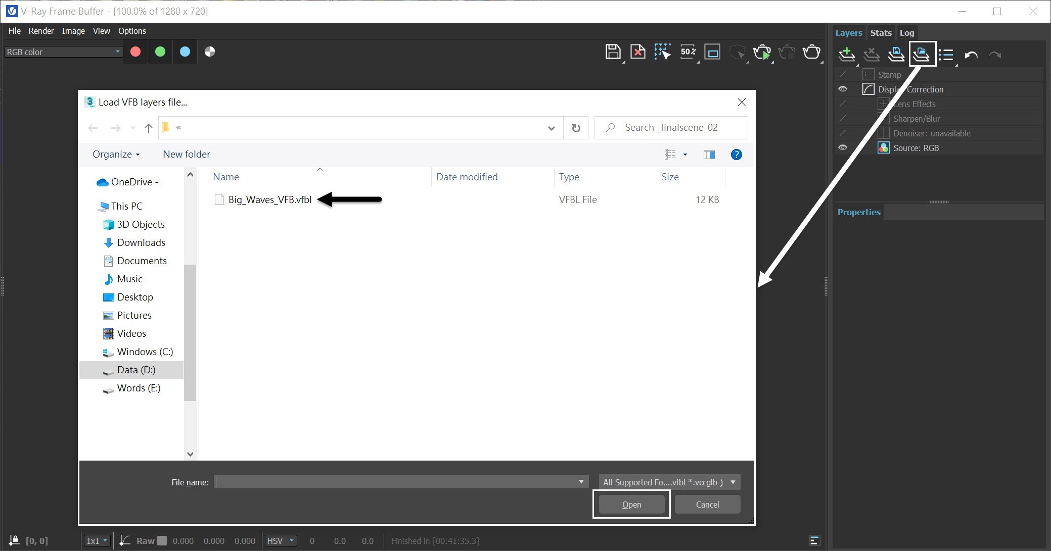
Open the V-Ray Frame Buffer and use the Create Layer icon to add layers for White Balance, Exposure, and Filmic tonemap.
Using V-Ray 5 as a render engine gives us the advantage of Filmic tonemap directly in the new VFB. However, if you are using an older version of V-Ray or 3ds Max 2017 or earlier, you can get a similar effect by using a proper LUT.

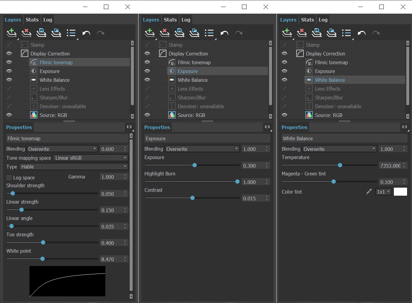
The final image is rendered using the V-Ray Frame Buffer with the color corrections and post effects set to:
Filmic tonemap:
Blending - Overwrite: 0.600
Type - Hable;
Shoulder strength: 0.050;
Linear strength: 0.150;
Linear angle: 0.035;
Toe strength: 0.400;
White point: 8.470.
Exposure:
Exposure: 0.300;
Highlight Burn: 1.000;
Contrast: 0.015.
White Balance:
Temperature: 7353.000;
Magenta - Green tint: 0.100.
The Filmic tonemap allows you to simulate the film response to light within the VFB.
Feel free to use other values for the post effects depending on your preferences.
Alternatively, you can load a Rendering Preset from the Big_Waves_VFB.vfbl file that is provided in the sample scene.
And here is the final rendered result (from frame 150 to frame 500).
(you can download nightlies from https://nightlies.chaos.com or get the latest official )