This page provides a step-by-step guide to understanding emitter types in Chaos Phoenix for Maya.
Overview
This is an Entry Level tutorial which requires no previous knowledge of Phoenix. A basic understanding of Maya would be helpful but is not a prerequisite for being able to follow along.
This tutorial is created using Phoenix 4.30 Official Release and V-Ray 5. You can download official Phoenix and V-Ray from https://download.chaos.com.
This tutorial covers the basic workflows for using the different emit modes in Phoenix for Maya. By the end of this process, you will gain an understanding of how to use multiple sources and emitter types to create complex simulations.
To follow the described steps, you will need the Phoenix for Maya plugin installed. If you notice a major difference between the results shown here and the behavior of your setup, please reach us using the Support Form.
This tutorial is a companion to go along with the QuickStart video posted on our YouTube channel.
To download project files: Download Project Files
Want to follow along but don’t have a license?: Download Free Trial
The video is created using Phoenix 3.0, but the text version of the tutorial is updated and uses Phoenix 4.30 Official. In any case of doubt you may refer to the text.
System Units Setup
Scale is crucial for the behavior of any simulation. The real-world size of the Simulator in units is important for the simulation dynamics. Large-scale simulations appear to move more slowly, while mid-to-small scale simulations have lots of vigorous movement. When you create your Simulator, you must check the Grid rollout where the real-world extents of the Simulator are shown. If the size of the Simulator in the scene cannot be changed, you can cheat the solver into working as if the scale is larger or smaller by changing the Scene Scale option in the Grid rollout.
The Phoenix solver is not affected by how you choose to view the Display Unit Scale - it is just a matter of convenience.
Go to Windows → Settings and Preferences → Preferences → Settings and set the Working Units to Centimeters.

Scene Setup
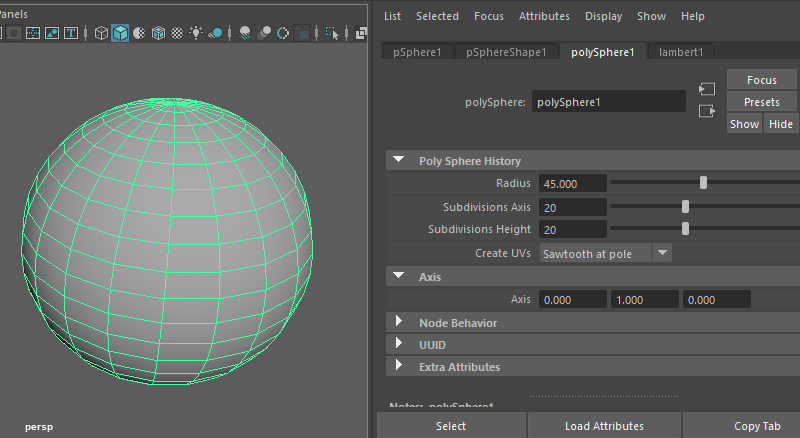
Create a new Maya file and make a Sphere with a radius of about 45 cm.
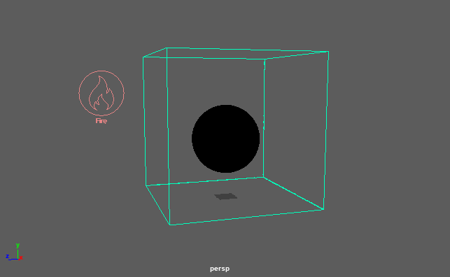
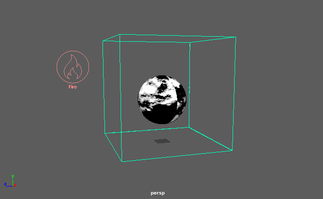
Select the sphere and click the Create Phoenix Fluid Simulator button in the Shelf. Draw out the grid around the sphere.
Move the sphere up to the center of the Simulator, as shown on the picture.
![]()

Open the Grid rollout and set the following values:
- Scene Scale: 1.0.
- Cell Size: 1.0 cm.
- Size XYZ: [ 188, 188, 188 ].

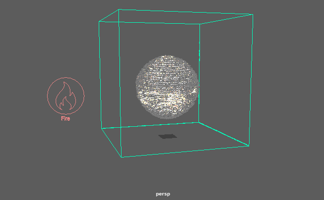
Click the Create a Fire/Smoke Source button on the Shelf and place the Source in your scene.
The Source object is a 2D non-renderable icon, so size and placement are only important for being able to select the Source when needed.


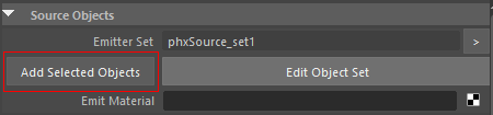
Select the sphere and then shift-select the Source and click Add Selected Objects in the Attribute Editor.
The Object Set of the Source is used to specify the geometry in the scene that will be used to emit fluid into the Simulator.
The Source node is where we control the Emitter properties, like the Emit Mode ant the Discharge. The sphere is the actual emitter of the fluid inside the Simulator.
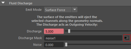
Notice that the Emit Mode is set to Surface Force by default. This means that the surface of the emitter, the sphere, will be used to discharge fluid along the geometry normals.
Set the Discharge to 5.

Move the Timeline Slider to Frame 50 and right click on the Discharge value (set to 5.0) and press Set Key. On Frame 51, change the Discharge value to 0.0 and Set Key.
This will animate the Discharge so it stays at a value of 5.0 from Frame 1 to 50, then turns off at Frame 51.

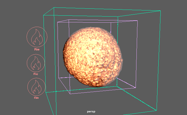
Start the simulation to see the fluid emitting from the surface of the sphere.
Stop the simulation after the first few frames.
Select the Simulator, open the Dynamics rollout, and set Gravity to 0.0 to prevent the Smoke from rising.

We only want to produce Smoke for this simulation, so select the Source and turn off Temperature.

Start the simulation, notice that only Smoke is created on the surface.
Stop the simulation.

Let's break up the regularity of the Smoke with a Mask.
Select the Fire/Smoke Source and click the Create Render Node button for Discharge Map. Select Noise.
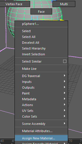
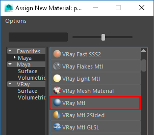
Select and right-click the sphere in the viewport. Select Assign New Material and choose a VRay Mtl.
Open the Hypershade and select the newly created VRayMtl node.
Navigate to the Textures tab and middle mouse click and drag the Noise Texture onto the VRayMtl Diffuse Color channel.
Close the Hypershade.

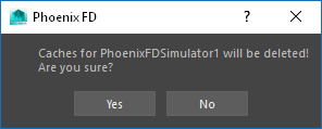
Select the Simulator and click the Clear Simulation Cache button from the Phoenix Shelf. Click Yes at the prompt.

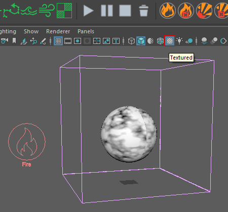
Enable Textures in the viewport by pressing 6 or clicking the Textured button shown in the picture.
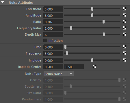
Go to Frame 1 and select the Noise Texture.
Set the Threshold to 5.0, the Amplitude to 6.0, Depth Max to 6, and the Frequency to 3.0.
Set the Noise Type to Perlin Noise.
Let's animate some of the values.
Right click and select Set Key for Time, at its default value of 0.0, and then also Set Key the Threshold at its current value of 5.0.
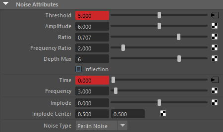
Frame 1
Then on Frame 50, set Time to 1.0 and Threshold to a value of 0.5.

Frame 50
We need to reverse the colors of the Noise texture.
In the Color Balance rollout, set the Default Color to Black and enable Alpha is Luminance.
In the Effects rollout, enable Invert.

Scrub the animation to see how the Noise Texture gradually appears over 50 frames.
Frame 1
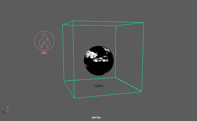
Frame 35
Frame 50
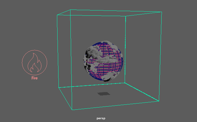
Start the simulation and Stop it at around Frame 35.
The Smoke production animates over time according to the animated Noise Texture on the sphere.

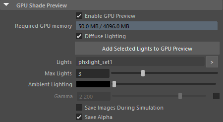
Select the Simulator, and go to the Preview rollout.
In the GPU Shade Preview section, check Enable GPU Preview.
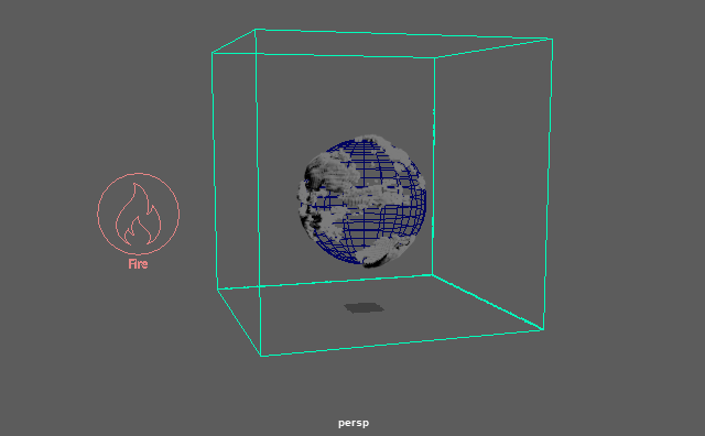
To see the effects better, switch the viewport to Wireframe by pressing 4.
Here is a GPU Preview of the simulation.
Let's add more Smoke. Select the Fire/Smoke Source and change the Smoke Multiplier to 2.0.

Select the Sphere Shape node in the Attribute Editor and locate the Extra Phoenix FD Attributes.
Uncheck Solid to make it a Non-Solid object in the simulation. This will prevent the sphere from interacting with the other emitters we will create next.

Let's create a new sphere that uses a different Emit Mode.
Press Ctrl + D to Duplicate the sphere.

Position the second sphere in the center of the original. Scale the new sphere down, so it is slightly smaller than the first sphere.
For better visibility, the object's Display Color of the second sphere can be changed.
In the Object Display rollout, open the Drawing Overrides and click Enable Overrides. Select a new Color.

The second sphere needs its own Fire/Smoke Source, so we need to disconnect it from the existing one in the scene.
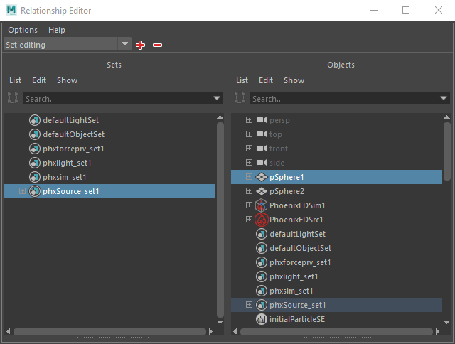
Select the Fire/Smoke Source and click the Edit Object Set button to launch the Relationship Editor.
On the left, select phxSource_set1 then deselect pSphere2 on the right.

From the Phoenix Shelf, create another Fire/Smoke Source in the scene.
With the new Source selected, use the Edit Object Set button to add pSphere2 to phxSource_set2.

In the Source settings, change the Emit Mode to Volume Brush. This mode will fill the volume of the emitter object gradually over time as a percentage set by the Brush Effect (%) value, which we will animate later.
Note that the Volume Emit Modes require the emitter to be Non-Solid. If it isn't, Phoenix will prompt you to change it.

This sphere will fill up with Temperature only, so uncheck Smoke in the Source settings.

Now, lets animate the Discharge of the second emitter.
At Frame 1 set the Discharge to 10 and Set Key.
Go to Frame 5 and set the value to 60, and Set Key.
Move to Frame 34, Set Key at a value of 30.
At Frame 35 and 50, Set Key to 60.
Finally, on Frame 51, Set Key at a value of 0.0.

Start the simulation. The second sphere is difficult to see while the simulation runs, so select the Simulator and open the Rendering rollout.
Under the Fire rollout, select the lower point in the Color and Intensity graph to activate it. Change the X value to 600. This allows the heat to become visible sooner.
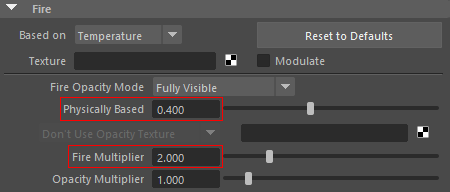
Set the Fire Multiplier to 2.0, and change Physically Based to 0.4. This reduces the Black-Body shader, which causes lower temperatures to be invisible and higher temperatures to be extremely bright. Overall, these adjustments will make the intensity of the Fire easier to see.

Stop the simulation sometime after Frame 50.
Scrub the Timeline to see the inner sphere gradually fill with Fire.

Frame 10

Frame 35

Frame 50
Go back to Frame 1 and select the inner sphere. Use Ctrl+ D to Duplicate it, and then scale the third sphere down.
Change it to a different color for better visibility using the Drawing Overrides as we did earlier in the tutorial.

First, remove the third sphere from phoenixSource_set2 as we did earlier in the tutorial.
Then, create a third Fire/Smoke Source and use the Edit Object Set button to add pSphere3 to phxSource_set3.

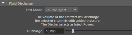
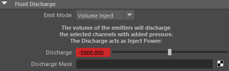
For this third Source, change the Emit Mode to Volume Inject.
This mode uses the object's volume for the emission, but the fluid will discharge with added pressure.
Now, lets animate the Discharge of the third emitter.
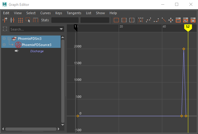
At Frame 1 set the Discharge to 0.0 and Set Key.
Go to Frame 49 and Set Key at value of 0.0.
Move to Frame 50, and change the Discharge to 2000 and Set Key.
For Frame 51, Set Key at value of 0.0. This will cause a quick burst for an explosion.
Not only can Inject Power be used to make an outward explosion, but a negative value can also be assigned to create an implosion.
Navigate to Frame 80 and set Discharge to 0.0 and Set Key.
At Frame 81 set it to -5000 and Set Key.
With these keyframes, an explosion will occur at frame 50 and an implosion will follow starting on Frame 81.
Frame 81
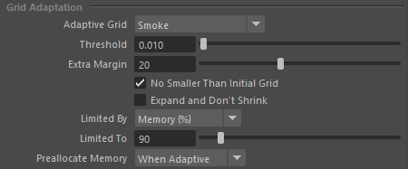
Before running the simulation, select the Simulator and navigate to the Grid rollout.
Enable the Adaptive Grid by setting it to Smoke. This expands the simulation grid in relation to the Smoke.
Lower the Threshold to 0.01 to increase the sensitivity for expanding the Grid, and change Extra Margin to 20 in order to detect fast-moving particles.
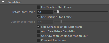
The simulation is already complete up to Frame 50, so to save on simulation time, go into the Simulation rollout and change the Start Frame to 50, then Start the simulation.
Stop the simulation after a few frames have passed.
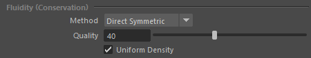
To add more swirls to the explosion, go to the Dynamics rollout and increase Conservation Quality to 40. Higher Conservation Quality values will create a stronger explosion shockwave and enhance the implosion effect created with the negative Inject Power value. With lower values, the implosion will not have enough power to draw in all the Smoke.
Since the explosion is not influenced by gravity, we can make it look suitable for outer space. To change the look of this explosion, navigate to the Rendering rollout and open the Fire tab. Navigate to the Color and Intensity graph. Double-click the lower arrows of the first color to bring up the Color Selector. Change it to green (HSV around 100, 1.0, 0.7).

To make the Fire appear hotter, increase the Fire Multiplier. If you set it to a value of 20, notice it might be a bit too much at the beginning of the explosion. In addition, the simulation will lose the gradual filling of the sphere. To fix this, we can animate this value.
To gradually increase of Temperature in the green Fire, go to Frame 50, change the Fire Multiplier to 2.0, and Set Key.
Move to Frame 51 and set the value to 20, then Set Key.

Frame 51
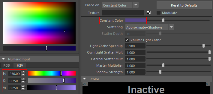
Expand the Smoke Color rollout. Move forward to Frame 56 and change the Smoke Constant color by clicking the color swatch. For this example, we'll make the color a dark purple (HSV 250, 0.75, 0.25).
To prepare your scene for rendering a simulation make sure V-Ray is set as your Renderer in the Render Settings window.

To add a light to the scene, click the V-Ray Sun button from the V-Ray Toolbar. In the Front viewport draw the direction at about a 40-degree angle pointing at the simulation.


Go back to the Perspective viewport, frame your shot, and select the Simulator.
In the Simulation rollout, enable Use Timeline Start Frame.

In the Grid rollout, click the Increase Resolution button twice to bring the resolution to around 25 million total cells.

In the Dynamics rollout, set the Steps Per Frame to 1.

Adjust the end time playback range to 150.

Start the simulation.
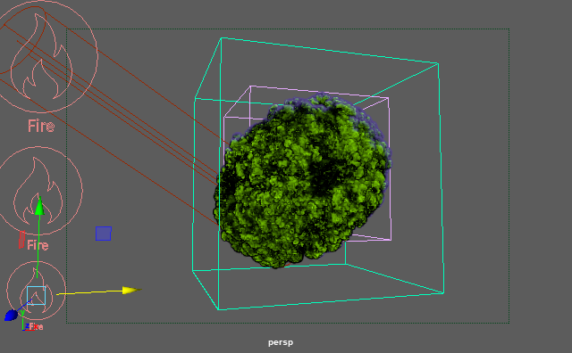
Here's a GPU Preview of frame 80.
Before starting to render, select the pSphere1 and go to the Render Stats rollout, disable Casts Shadows, Primary Visibility, Visible in Reflections, and Visible in Refractions. This prevents the sphere from appearing in the final render.
Repeat this step for pSphere2 and pSphere3.
Now the spheres won't be visible in the final render.

Go to the Sun settings, set the Intensity multiplier to 0.07.

Here is the final render of frame 80.

And the rendered sequence.