This page provides a tutorial on creating a lava simulation with Chaos Phoenix in Maya.
Overview
This is an Advanced Level tutorial. The workflow for setting up the shot, and the Phoenix settings involved in the simulation are explained in detail. However, creating a production quality shot of a similar nature may require some tweaks to the lighting, materials and/or the Phoenix simulation.
This simulation requires Phoenix FD 4.10 Official Release and V-Ray Next Official Release for Maya 2018 at least. You can download official Phoenix and V-Ray from https://download.chaos.com. If you notice a major difference between the results shown here and the behavior of your setup, please reach us using the Support Form.
The instructions on this page guide you through the process of using Phoenix's Variable Viscosity capabilities in order to simulate molten lava or metal cooling and hardening over a period of time.
To download project files: Download Project Files
Want to follow along but don’t have a license?: Download Free Trial
Units Setup
Scale is crucial for the behavior of any simulation. The real-world size of the Simulator in units is important for the simulation dynamics. Large-scale simulations appear to move more slowly, while mid-to-small scale simulations have lots of vigorous movement. When you create your Simulator, you must check the Grid rollout where the real-world extents of the Simulator are shown. If the size of the Simulator in the scene cannot be changed, you can cheat the solver into working as if the scale is larger or smaller by changing the Scene Scale option in the Grid rollout.
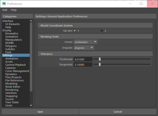
Go to Windows → Settings and Preferences → Preferences → Settings and set the Working Units to centimeters.
Scene Layout
The final scene consists of the following elements:
- A Poly Model -> Box used as the source geometry for the liquid. An animated Texture Deformer is applied to the geometry to add variation the emission.
- A set of rocks geometry provided with the rocks.abc file.
- A Phoenix Liquid Source with the Box geometry in its Object Set list. The Source is in Surface Force mode and Noise is enabled for extra randomization.
- A Phoenix Fluid Simulator with some tweaks in the Grid, Dynamics and Rendering rollouts.
- A Particle Tuner used to change the Viscosity of the liquid during the simulation.
- A V-Ray Physical camera with minor tweaks for final rendering.
- A V-Ray Dome Light.
A V-Ray Plane used as an infinite ground surface.

Scene Setup
Set the Windows → Settings/Preferences → Preferences → Time Slider from 0 to 150 so that the Timeline goes from 0 to 150.

Import the rocks.abc geometry by going to Cache -> Alembic Cache -> Import Alembic... and select the file.
We start off with pre-built geometry to save time setting up the scene. Feel free to use your own personal models.
The size of the bounding box of the three rocks used in this example is:
X/Y/Z: [ 155/60/75 ].

Let's add the geometry used to emit the lava.
Create a Poly Modeling -> Box.
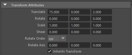
Use the Move tool to place the box above the rocks. The exact transform values are X/Y/Z: [ 73/137/3 ].
Set the Width/Height/Depth to [ 33/5/38 ], and the Subdivisions along the Width/Height/Depth to [ 5/1/5 ].
The subdivisions will be needed later in this tutorial when a Texture Deformer is added to the Box to randomize the emission pattern.

Add a Phoenix FD → Create → Liquid Source. The Liquid Source is a Phoenix helper node used to tell the Simulator which objects in the scene will emit, how strong the emission will be, etc.
Add the Box primitive into the Liquid Source's Object Set.
The Object Set of the Source is used to specify the geometry in the scene that will be used to emit fluid into the Simulator.

Create a Phoenix Fluid Simulator.
Set the Grid → Cell Size to 1.0cm. The lower the Cell Size is, the more detailed the simulation will be but the longer it will take to complete. We start off with a reasonably small value so we can iterate quickly over different parameter variations.
The Size of the Simulator is set to X/Y/Z: [ 80/150/80 ].
Set the Grid → Container Walls → Y: Jammed (-). When a Container Wall is Jammed, it acts as a solid wall against which the liquid will collide.

The exact Position of the Simulator in the scene is X/Y/Z: [ 75/0/2 ].
To the right is a Viewport Preview showing the result of the simulation so far.
At the moment, liquid is being emitted from the entire Box geometry.
Instead, we would like to emit only from the bottom faces of the Box.
We take a look at one possible solution in the next step.
The Phoenix Source nodes can use an Emit Material assigned only on those faces which will be used for emission of fluid.
Select the Box geometry and go into Face Selection mode.
Select only the bottom faces which will be used for the emission and assign them a new Lambert material. Change its name to face_mat.
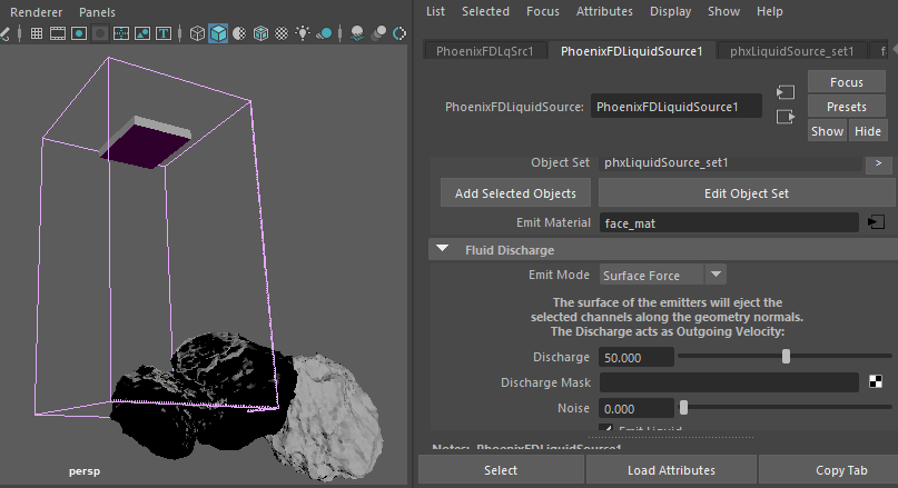
Select the Phoenix Source and add the face_mat material to the Emit Material slot.
To the right is a Viewport Preview showing the result of the simulation so far.
The liquid is now correctly being emitted only from the bottom faces of the Box geometry.
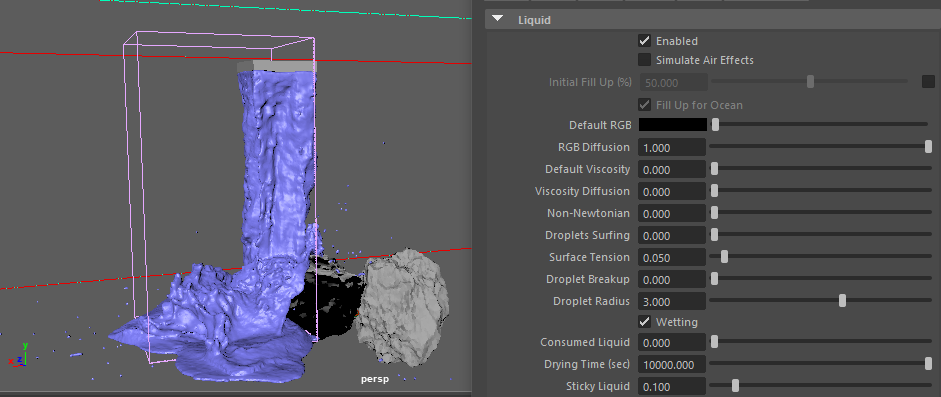
Select the Phoenix Liquid Source and set Viscosity to 0.2.
Viscosity emulates thickness - the higher this value is, the more the liquid will resemble thick mud, honey or in this case - lava.

Under the Output rollout of the Phoenix Simulator, enable the export of the Viscosity Grid Channel.
Also enable the export of the Viscosity Liquid Particle Channel.
Outputting those channels is required for the calculation of Viscosity for the liquid to work.
Enable the RGB Channel. This is required for the simulation of the RGB channel to work.
Make sure to also enable the Velocity Channel. The Velocity Grid Channel is used when rendering with Motion Blur.
Enable the Age Channel. This channel is used by the Particle Tuner, so it can randomize the viscosity by the age of the liquid particles.

To the right is a Viewport Preview showing the result of the simulation so far.
The liquid feels much thicker now, and the stepping artifacts are much less pronounced.
In the next step we will animate the Box geometry to move to the right so the lava pours all over the rocks.
Animate the Box geometry with the following keyframes:
Frame 0: [ X: 73 | Y: 137 | Z: 3 ]
Frame 67: [ X: -24.5 | Y: 137 | Z: 3 ]
Frame 132: [ X: 53 | Y: 137 | Z: 3 ]
Frame 150: [ X: 45 | Y: 137 | Z: 4 ]

Enable Phoenix Simulator → Grid → Grid Adaptation. Set the Adaptive Grid to Temperature/Liquid. The red box in the screenshot to the right is a preview of the Maximum Bounds for the simulation. Adaptive Grid is a huge time saver - the initial grid is dynamically expanded to accommodate the movement of the liquid, cutting down on both processing time and memory. If you notice any clipping, increase the Extra Margin to a value of 5 - 10. This will add a few extra voxels at the borders during adaptation.
Enable the Manual Adaptation Limits and set the limits to X: [ 100, 200 ], Y: [ 0, 0 ] and Z: [ 100, 100 ].

To the right is a Viewport Preview showing the result of the simulation so far.
Now that the liquid is pouring all over the rocks we can see that it's not sticking to them at all.
In the next step we will enable Wetting so the lava can stick to the rocks.
Enable Phoenix Simulator -> Liquid -> Wetting. When Wetting is enabled, Phoenix generates another set of particles called WetMap particles. Those particles are created at the point of contact between the liquid and the scene geometry and can be used to drive shaders (through a Phoenix Particle Texture) or specify where the liquid should try to adhere to. You can disable Wetting for a specific object in your scene from its Phoenix FD Extra Attributes.
Set Sticky Liquid to 0.1. The lava will now try to adhere to the rocks.

To the right is a Viewport Preview showing the result of the simulation so far.
The lava is now naturally flowing over the rocks.
At the moment the entire bottom side of the box geometry is emitting lava giving the fluid an unnatural cubic appearance.
In the next few steps we will randomize the emission for a more natural looking lava.
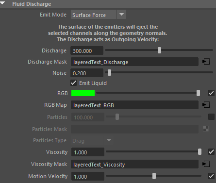
Select the Phoenix Liquid Source and set the Noise parameter to 0.2. This option works as a multiplier on the Discharge - some areas of the emission geometry will emit with a higher Discharge while other areas will be weaker.
Plug a Layered Texture in the Discharge Mask slot.
Finally, increase the Discharge to 300 - this value is completely arbitrary and can be modified based on the requirements of your setup.
Layered Textures are used for compositing two or more textures or colors using various blend modes or texture masks. When a texture is attached to the Alpha slot, it works as a mask and the white or bright areas of the mask texture indicate areas of the current texture that are used in the composite, while black areas indicate areas of the current texture that do not contribute to the composite.

Rename the Layered Texture to layeredText_Discharge.
Create two Layered Texture Attributes.
Set the Color of the first one to RGB [ 64, 64, 64 ] and the Color of the second one to RGB [ 255, 255, 255 ].
Select the first Layered Texture Attribute and assign a Noise texture to the Alpha slot.
Set the Blend Mode to Over.
Enable Alpha is Luminance.

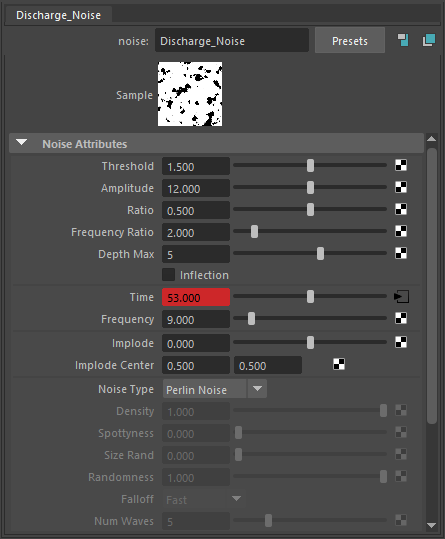
Rename the Noise texture to Discharge_Noise.
Here are the exact values for the Noise texture:
Noise Type: Perlin Noise
Threshold: 1.500
Amplitude: 12.000
Ratio: 0.500
Frequency Ratio: 2.000
Max Depth: 5
Time: animated with the following keyframes:
Frame 0: 53
Frame 150: 30
Frequency: 9.000
Enable Alpha is Luminance.
Feel free to tweak the settings based on your own artistic judgement.
In Maya all textures are created with a Place2d/3dTexture attached to them. Place2d/3dTexture is a utility node that controls how a 2d/3d texture is placed onto an object. Normally a Place2d/3dTexture node is created automatically by the system when you texture-map an attribute using a 2d/3d texture. You can control the position, size, and rotation of the texture on the surface by using the Coverage, Translate Frame and Rotate Frame attributes.
In this part of the tutorial we will use the place2dTexture, attached to the Discharge_Noise to achieve a better fluid dynamics.
Go to 2d Texture Placement Attributes and set the Rotate Frame to 135.0.

Reduce the Phoenix Simulator → Grid → Cell Size to 0.640 so the extra detail provided by the Noise texture can come through.

To the right is a Viewport Preview showing the result of the simulation so far.
The emission pattern is now much more natural.
Furthermore, the higher Discharge is causing the lava to splash as it hits the rocks.
For even more randomness, add a Deform -> Texture to the Box emission geometry:
Here are the exact values used in this setup:
Point Space: Local
Direction: Handle
Texture: assign a Volume Noise texture
Strength: 1

Rename the Volume Noise texture to Tex_Deformer_Noise.
Here are the exact values for the Volume Noise texture:
Noise Type: Perlin Noise
Threshold: 0.000
Amplitude: 2.000
Ratio: 0.707
Frequency Ratio: 1.000
Max Depth: 3
Time: animated with the following keyframes:
Frame 0: 0
Frame 150: 4
Frequency: 0.050
Feel free to tweak the settings based on your own artistic judgement.

Increase the Phoenix Simulator → Liquid → Surface Tension to 0.05. Surface Tension helps to keep the liquid together.
To the right is a Viewport Preview showing the result of the simulation so far.
At the moment the viscosity of the lava is completely uniform. Real lava has different viscosity depending on its temperature. Hot lava resembles liquid and stiffens as it cools down.
In the next step we will randomize the Viscosity with a Layered Texture combined with a Noise texture.
Place a Layered Texture in the Viscosity Mask slot.
Increase the Viscosity parameter to 1.0. Usually a value of 1.0 is way too high but since the Layered Texture has high-frequency detail, with most of the values in the texture much below 1.0, the final result will be significantly lower after the Viscosity is multiplied by the provided texture map.

Rename the Layered Texture to layeredText_Viscosity.
Create two Layered Texture Attributes.
Set the Color of the first one to RGB [ 56, 56, 56 ] and the Color of the second one to RGB [ 223, 223, 223 ].
Select the first Layered Texture Attribute and assign a Noise texture to the Alpha slot.
Set the Blend Mode to Over.
Enable Alpha is Luminance.

Rename the Noise texture to Viscosity_Noise.
Here are the exact values for the Noise texture:
Noise Type: Billow
Threshold: 0.400
Amplitude: 0.800
Ratio: 0.700
Frequency Ratio: 1.200
Max Depth: 5
Time: animated with the following keyframes:
Frame 0: 0
Frame 150: 6
Frequency: 40.000
Enable Alpha is Luminance.
Feel free to tweak the settings based on your own artistic judgement.

To the right is a Viewport Preview showing the result of the simulation so far.
The difference after modifying the Viscosity with a texture is not immediately obvious but once the Cell Size is reduced for the final simulation, individual chunks of lava will start forming based on the different viscosity values.
Solidifying with a Particle Tuner
In this section of the tutorial, we look into the process of using a Particle Tuner to increase and randomize the viscosity of the lava over time. Real-world lava solidifies as it cools down and we want to replicate this behavior.
The Particle Tuner assesses all particles in the simulation and changes their values if they pass a certain condition.
In this example we will raise the viscosity of particles as their age increases.
The conditions can be very simple, but you can also build more complex conditions with the Particle Tuner's expression operators.
In this case the Particle Tuner expression tree is created as follows:
- If the Age of a particle is Greater Than a Random value Between 1.0 and 2.0 seconds
Then the Viscosity is set to Increase By 1.0
Over the Buildup Time which is set to 2.0 seconds.


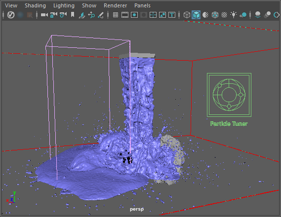
To the right is a preview showing the result of the simulation so far.
The lava now splashes as it hits the rocks but calms down and solidifies as it settles on the ground.
Note the small droplets of lava flying away from the rocks geometry - in the next couple of steps we will fix this problem by increasing the Steps Per Frame and the Scene Scale, and reducing the Cell Size of the simulation.
There are many stray particles flying all over the place as the lava collides with the rocks. Not only is this effect unnatural but it also drastically increases the simulation time by expanding the Adaptive Grid to its maximum extents.
Increase the Phoenix Simulator → Dynamics → Steps Per Frame to 2 to remedy this.
Increasing the Steps Per Frame will usually produce calmer fluids but will increase the simulation time. Each simulation step kills fine details, and thus for maximum detail it's best to use the lowest possible SPF that runs without any of the issues mentioned above. You can find more information on Steps Per Frame here.

To the right is a preview, showing the result of the simulation so far.
Increasing the Steps Per Frame substantially reduced the detail in the simulation but also helped to resolve the problem with individual droplets flying all over the place.
We can further reduce the Cell Size and thus increase the grid resolution to gain back some of that detail.

Increase the Scene Scale to 3.0. Bigger scale would make the fluid move more slowly.
Reduce the Cell Size to 0.35.
Expand the Manual Adaptation Limits to X: [ 286, 571 ], Y: [ 0, 0 ] and Z: [ 350, 350 ].


To the right is a Viewport Preview showing the result of the simulation so far.
This is the final shape of the Lava simulation.
We increased the Steps Per Frame to eliminate the stray droplets.
Increasing the Scene Scale made the fluid move more slowly.
Reducing the Cell Size gave us more detail in the fluid.
In the next step we will set up the RGB channel for the Lava shader.
Place a Layered Texture in the RGB Mask slot of the Liquid Source.

Rename the Layered Texture to layeredText_RGB.
Create two Layered Texture Attributes.
Set the Color of the first one to RGB [ 254, 102, 1 ] and the Color of the second one to RGB [ 180, 13, 0 ].
Select the first Layered Texture Attribute and assign a Noise texture to the Alpha slot.
Set the Blend Mode to Over.
Enable Alpha is Luminance.

Rename the Noise texture to RGB_Noise.
Here are the exact values for the Noise texture:
Noise Type: Billow
Threshold: 0.450
Amplitude: 0.617
Ratio: 0.6
Frequency Ratio: 2.000
Max Depth: 10
Time: 0
Frequency: 50.000
Enable Alpha is Luminance.
Feel free to tweak the settings based on your own artistic judgement.

Scroll down to the Effects tab of the RGB_Noise texture and enable Invert.

At this point you should have three different Layered Textures, combined with Noise textures, for Discharge, RGB and Viscosity.
Set Phoenix Simulator → Liquid rollout → RGB Diffusion to 0.1.
The RGB Diffusion parameter controls how quickly the colors of particles are mixed over time during the simulation. When set to 0, each liquid particle carries its own color, and the color of each individual particle does not change when liquids are mixed. This means that if red and green liquids are mixed, a dotted red-green liquid will be produced instead of a yellow liquid. This parameter allows the colors of particles to change when the particles are in contact, thus achieving uniform color in the resulting mixed liquid. For more information, see the RGB Diffusion example.

Camera & Light
For this setup a VRayPhysicalCamera is used.
To add Physical Camera parameters, select the Maya camera used for rendering.
Under its Shape node in the Attribute editor go to Attributes -> V-Ray -> Physical Camera.
The Film Gate is set to 36.0.
The F-Number is set to 0.8.
The Shutter Speed is set to 1000.
The Film Speed (ISO) is set to 100.
Enable the Exposure color correction and set the White Balance to RGB [ 255, 210, 160 ].
Enable Bokeh effects -> Number of Blades set to 7. Blades Rotation is set to 0.300, with a Center Bias of 1.
Both Depth of Field and Motion Blur are Enabled.
The exact position of the Camera is X/Y/Z: [ 2/108/-318 ].
and of the Camera Aim is X/Y/Z: [ 16/44/-11 ].
The V-Ray Settings -> Rendering Output Width/Height is set to 960/540 for the example renders below.


Go to Create → Lights → V-Ray Dome Light.
Set the Light Type to Dome Spherical.
Set the Multiplier to 6.
Enable Options → Invisible so the Dome Light is not visible in the rendered image but still provides illumination in the scene.

Set the Overrides → Environment → Background texture to RGB [ 15, 16, 21 ].

Add a V-Ray Infinite Plane by going to Create → V-Ray → Create V-RayPlane.
To the right is a rendered image of the current setup plus the basic materials we create in the next section.
Materials for the Rocks and Ground
Assign a V-Ray Material to the V-Ray Plane and rename it to mtl_Ground.
Set the Diffuse Color to RGB [ 2, 2, 2 ].
Set the Reflection Color to RGB [ 21, 21, 21 ].
Set the Reflection Glossiness to 0.65.
Set the Bump Mult to 0.700.

Add a new Layered Texture and plug it into the Bump Map slot of mtl_Ground.
Rename the Layered Texture to layeredTexture_mtl_Ground.
Create two Layered Texture Attributes.
Set the Color of the first one to RGB [ 0, 0, 0 ] and the Color of the second one to RGB [ 255, 255, 255 ].
Select the first Layered Texture Attribute and assign a Noise texture to the Alpha slot.
Set the Blend Mode to Over.
Enable Alpha is Luminance.

Rename the Noise texture to groundBump.
Here are the exact values for the Noise texture:
Noise Type: Perlin Noise
Threshold: 0.500
Amplitude: 0.700
Ratio: 0.300
Frequency Ratio: 4.000
Max Depth: 5
Time: 0
Frequency: 30.000
Enable Alpha is Luminance.
Scroll till the Effects tab and enable Invert.
Feel free to tweak the settings based on your own artistic judgement.

Here's a rendered image of the V-Ray ground plane with mtl_Ground applied.

For the rocks, assign a V-Ray Material and rename it to mtl_Rocks.
Set the Diffuse Color to RGB [ 2, 2, 2 ].
Set the Reflection Color to RGB [ 21, 21, 21 ].
Set the Reflection Glossiness to 0.65.
Set the Bump Mult to 1.

Add a new Layered Texture and plug it into the Bump Map slot of mtl_Rocks.
Rename the Layered Texture to layeredTexture_mtl_Rocks.
Create two Layered Texture Attributes.
Set the Color of the first one to RGB [ 0, 0, 0 ] and the Color of the second one to RGB [ 255, 255, 255 ].
Select the first Layered Texture Attribute and assign a Volume Noise texture to the Alpha slot.
Set the Blend Mode to Over.
Enable Alpha is Luminance.

Rename the Volume Noise texture to rocksBump.
Here are the exact values for the Volume Noise texture:
Noise Type: Perlin Noise
Threshold: 0.500
Amplitude: 0.500
Ratio: 0.300
Frequency Ratio: 1.000
Max Depth: 5
Time: 0
Frequency: 1.000
Enable Alpha is Luminance.
Scroll till the Effects tab and enable Invert.
Feel free to tweak the settings based on your own artistic judgement.

Here's a rendered image of the Rocks geometry with mtl_Rocks applied.

Material for the Solid Lava
For the solid lava (the one with high viscosity), assign a V-Ray Material to the Phoenix Simulator and rename it to coldSolidLava. This material is the base for the final Complex Lava material we create in the next section.
Set the Diffuse Color to RGB [ 1, 2, 3 ].
Set the Reflection Color to RGB [ 55, 55, 55 ].
Set the Reflection Glossiness to 0.72.
Set the Bump Mult to 0.400.

Add a new Volume Noise texture and plug it into the Bump Map slot of the coldSolidLava material.
Rename the Volume Noise texture to solidLavaBump.
Here are the exact values for the Noise texture:
Noise Type: Perlin Noise
Threshold: 0.000
Amplitude: 0.200
Ratio: 0.707
Frequency Ratio: 2.000
Max Depth: 3
Time: 0
Frequency: 0.200
Enable Alpha is Luminance.
Feel free to tweak the settings based on your own artistic judgement.

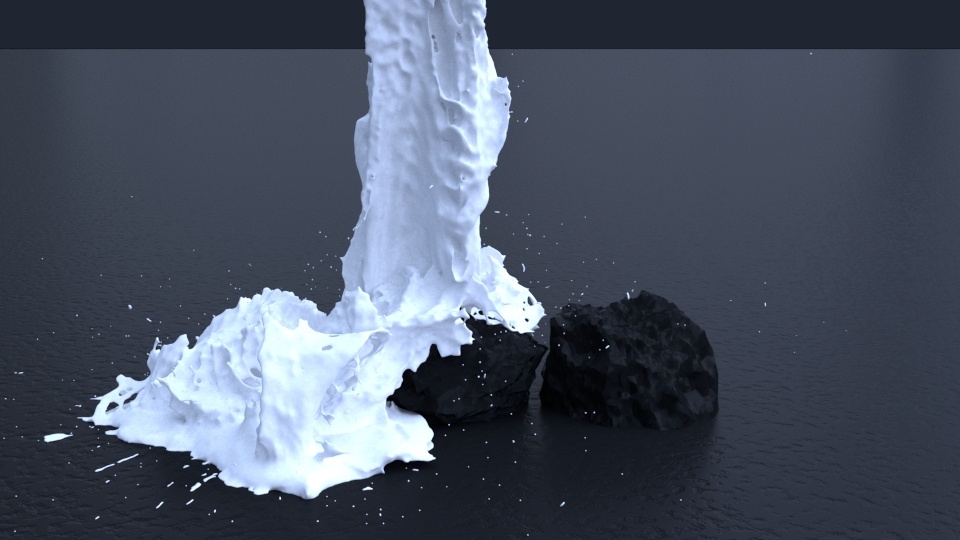
Here's a rendered image of the Lava with the coldSolidLava material applied to the Simulator.

Material for the Liquid Lava
The material for the liquid lava consists of a regular V-Ray Material (coldLiquidLava) and a V-Ray Light Material (hotLiquidLava) blended together based on the output of a Phoenix Grid Texture reading the simulation's RGB Channel.
The hotLiquidLava Light Material is the core of the lava shader - the emitted light's color is based on the RGB Channel read through a Grid Texture.
The coldLiquidLava V-Ray Material is added into the mix for additional variation. Even very hot lava flows in real life have chunks of rocks that do not emit light. Having only a single Light Material would look unrealistic.
The Blend input of the liquidLava Blend Material is driven by the same RGB Channel - a Color Correct node is used to desaturate the RGB Channel values.

To start off, create a V-Ray Blend Material and assign it to the Phoenix Simulator. Rename it to liquidLava.
Create a V-Ray Material and plug it into the Base Material input of the liquidLava Blend Material. Rename it to coldLiquidLava.
Set the Diffuse Color to RGB [ 1, 2, 3 ].

Create a V-Ray Light Material and plug it into the Coat Material 0 input of the liquidLava Blend Material. Rename it to hotLiquidLava.
Set the Color to RGB [ 0, 0, 0 ] - we use a Phoenix Grid Texture reading the simulation RGB Channel to drive the color of the emitted light.
Set the Color Multiplier to 100 - this will affect the intensity of the emitted light.

Create a Phoenix Texture and plug it into the hotLiquidLava Light Material's Light Color input. Rename it to gridRGB.
Write the name of the Simulator in the Simulator Node Name tab.
Set the Channel to Grid RGB - this is the channel the texture will read from the cache files.
Set the Sampler to Spherical. You can think of the sampling process as Anti-Aliasing - the Box sampler will give you a rough texture, the Linear will try to smooth the colors and the Spherical will produce the smoothest result. Note that Spherical is 20-30% slower than Linear so make sure to check if the additional sampling at the expense of render time is worth with your setup.
Set the Color Scale to 0.590. This value multiplies the color output values of the Grid Texture. In our case we use it to achieve more complex shader of the lava.

Create a Color Correction node and plug the gridRGB texture into the Color slot. Rename the Color Correction node to desaturateRGB.
Set the Color Correct → Value to 2.
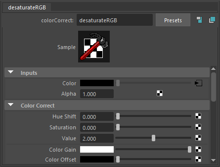
To the right is a rendered image of the desaturateRGB Color Correction texture applied to the Diffuse Color of a default V-Ray Material.
Plug the gridRGB texture into the Blend Amount slot of the liquidLava Blend Material.
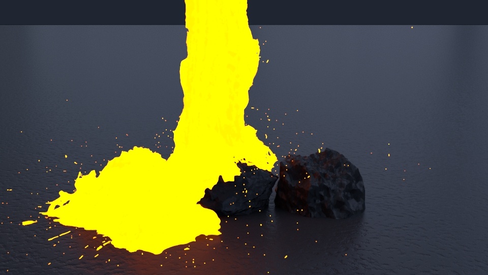
To the right is a rendered image of the current setup.
Complete the Lava Shader
The final material for the lava consists of the coldSolidLava and liquidLava materials we prepared in the previous two sections of this tutorial.
A V-Ray Blend Material is used at the final wrapper. The Blend Material is driven by a Phoenix Texture reading the Viscosity Grid Channel. Recall that the Viscosity in the simulation increases as the simulation progresses in time. Thus, higher viscosity values should correspond to solid lava with the coldSolidLava material applied.

Create a V-Ray Blend Material and rename it to Lava.
Plug the coldSolidLava material in the Base Material slot.
Plug the liquidLava material in the Coat Material 0 slot.

Create a Phoenix Texture and rename it to gridViscosity.
Write the name of the Simulator in the Simulator Node Name tab.
Set the Channel to Grid Viscosity - this is the channel the texture will read from the cache files.
Set the Sampler to Spherical. You can think of the sampling process as Anti-Aliasing - the Box sampler will give you a rough texture, the Linear will try to smooth the colors and the Spherical will produce the smoothest result. Note that Spherical is 20-30% slower than Linear so make sure to check if the additional sampling at the expense of render time is worth with your setup.
Set the Color Scale to 3.500.
Under the Effects tab enable Invert. If the Grid Texture is not inverted, the high-viscosity areas of the simulation will receive the liquidLava material instead of the coldSolidLava material.

Plug the gridViscosity texture into the Blend Amount slot of the Lava Blend Material.
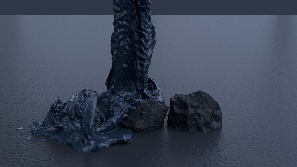
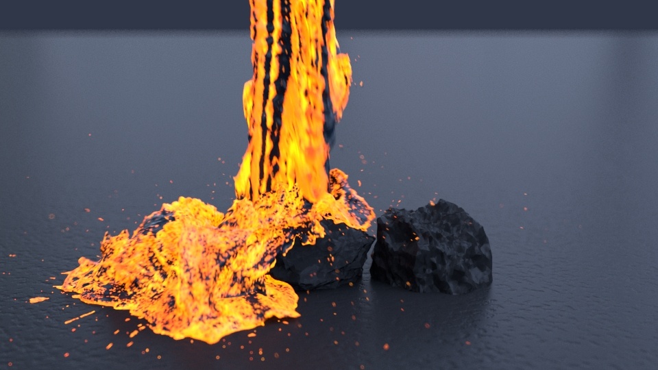
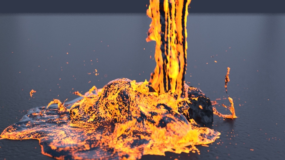
To the right is a rendered image of the final Lava material.
Mesh Smoothing for the Lava Mesh
Optionally, you may choose to enable some Simulator → Rendering → Mesh Smoothing options if your lava simulation looks too sharp/jagged.
The settings for the smoothed image to the right are Simulator → Rendering → Use Liquid Particles enabled, and a Smoothness of 5.
![]()
Lava No Smoothing
Lava With Smoothing
V-Ray Frame Buffer
For the final image, some corrections are made in the V-Ray Frame Buffer.
Bloom/Glare Effect is enabled from the Lens Effects panel. The Size is set to 22, with a Bloom of 0.11. The Intensity is set to 5.00 and the Threshold to 0.11.
Exposure is enabled from the Corrections panel and reduced to -1 to counter the brightening effect of the Bloom effect.
White Balance is also enabled and Temperature set to 8000 to pull the image away from the blue overall tint created by the Bloom effect.

Final Results

