The Reflection tab is part of the V-Ray Material parameters.
Reflection
BRDF Type – Determines the type of BRDF (the shape of the highlight). See the BRDF type example for more information.
GGX – GGX Microfacet highlight/reflections. Specular highlights have a bright center with a longer falloff.
Phong – Phong highlight/reflections. Specular highlights have a bright center with no falloff.
Blinn – Blinn highlight/reflections. Specular highlights have a bright center with a tight falloff.
Ward – Ward highlight/reflections. Specular highlights have a bright center with a falloff broader than Blinn, but tighter than Microfacet GTR (GGX).
GGX is the most modern and flexible BRDF type and is able to better represent a broad range of materials thanks to its ability to control the shape of the specular lobe.
There currently isn't any particular performance difference between models and there is little reason to choose any of the other types.
Color – Specifies the reflection color of the material. Note that the reflection color dims the diffuse surface color. See the Reflection Color example for more information.
Texture – Specifies a texture file to be used for the reflection.
Mix Strength – Specifies a blend amount between the texture map and the color.
Glossiness – Controls the sharpness of reflections. A value of 1.0 creates perfect mirror-like reflections; lower values produce blurry or glossy reflections. Use the Reflection Subdivs parameter to control the quality of glossy reflections. See the Reflection Glossiness example for more information.
Texture – Specifies a texture file to be used for the glossiness.
Mix Strength – Specifies a blend amount between the texture map and the glossiness amount.
GGX Tail Falloff – Controls the transition from highlighted areas to non-highlighted areas when the BRDF Type is set to GGX.
Texture – Specifies a texture file to be used for the GGX Tail Falloff.
Mix Strength – Specifies a blend amount for the texture map.
Mix Type – Specifies how the texture file is blended with the GGX Tail Falloff value. The texture is applied to a layer above the Falloff value.
Normal – When applied, the texture is blended normally. A Mix Strength of 100% makes the texture completely opaque, hiding the Falloff value below.
Add – When applied, the texture's value is added to the Falloff value.
Subtract – When applied, the Falloff value is subtracted from the texture's value.
Multiply – When applied, the texture is multiplied by the Falloff value.
Metalness – Controls the reflection model of the material from dielectric (metalness 0.0) to metallic (metalness 1.0). Note that intermediate values between 0.0 and 1.0 do not correspond to any physical material. This parameter can be used with PBR setups coming from other applications. The reflection color should typically be set to white for real world metals.
Texture – Specifies a texture file to be used for the metalness.
Mix Strength – Specifies a blend amount between the texture map and the metalness amount.
GTR Energy Compensation – Compensates GTR lost energy and an accurate Fresnel formula for conductors is used for metals. This option is enabled by default for all newly created materials and is hidden from the UI. It is visible in older scenes.
Use Roughness – This option controls how Glossiness is interpreted. When Use Roughness is selected, the Glossiness inverse value is used. For example, if Glossiness is set to 1.0 and Use Roughness is selected, this results in diffuse shading. Conversely, if Glossiness is set to 0.0 and Use Roughness is selected, this results in sharp reflection highlights.
Use Bump to Glossiness – This option is available only when a Bump texture is attached to the material. Enable this to convert the Bump texture into a Glossiness texture and use it as a Glossiness input. This method creates more matte highlights.

Example: BRDF Type
The following examples demonstrate the different Types of BRDF.

Microfacet GTR (GGX)
Modern, versatile BRDF type suitable for all kinds of materials.

Phong
Best used for plastic surfaces.

Blinn
Multi-purpose BRDF suitable for many common materials.

Ward
Useful for cloth materials and chalk-like surfaces.
Slide to change BRDF type.
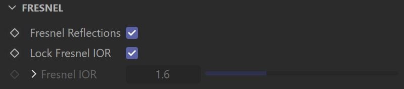
Fresnel
Fresnel Reflections — When enabled, makes the reflection strength dependent on the viewing angle of the surface. Some materials in nature (glass etc) reflect light in this manner. Note that the Fresnel effect depends on the index of refraction as well. See the Fresnel example for more information.
Lock Fresnel IOR – Allows the user to unlock the Fresnel IOR parameter for finer control over the reflections.
Fresnel IOR – The Index of reflection to use when calculating Fresnel reflections. Normally this is locked to the Refraction IOR parameter, but you can unlock it for finer control. A texture can be attached to this slot.
Texture – Specifies a texture file to be used for the Fresnel IOR.
Mix Strength – Specifies a blend amount between the texture map and the fresnel IOR value.
Mix Type – Specifies how the texture file is blended with the Fresnel IOR value. The texture is applied to a layer above the Fresnel IOR value.
Normal – When applied, the texture is blended normally. A Mix Strength of 100% makes the texture completely opaque, hiding the Fresnel IOR value below.
Add – When applied, the texture's value is added to the Fresnel IOR value.
Subtract – When applied, the Fresnel IOR value is subtracted from the texture's value.
Multiply – When applied, the texture is multiplied by the Fresnel IOR value.
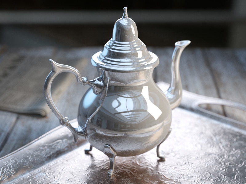
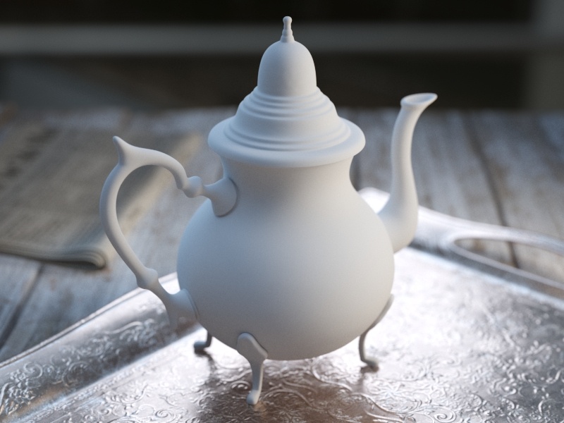
Example: Reflection Color
This example demonstrates how the Reflect color parameter controls the reflectivity of the material. Note that this color also acts as a filter for the Diffuse color (e.g. stronger reflections dim the diffuse component).
Example: Fresnel
This example demonstrates the effect of the Fresnel reflections option. Note how the strength of the reflection varies with the Fresnel IOR of the material. For this example, the Reflect color is pure white (255, 255, 255).
Reflect = 0, 0, 0
Reflect = 51, 51, 51
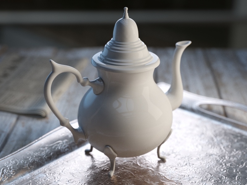
Reflect = 102, 102, 102

Reflect = 153, 153, 153
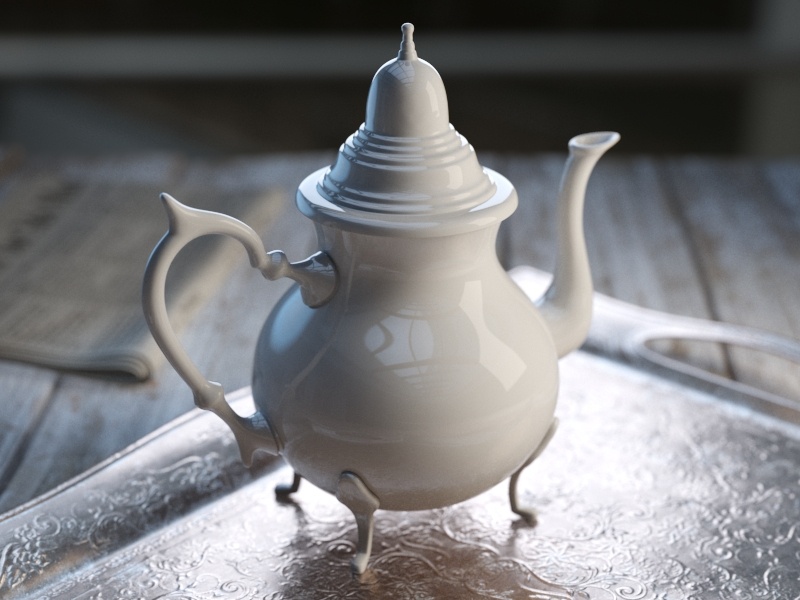
Reflect = 204, 204, 204

Reflect = 255, 255, 255

Fresnel IOR = 1.6

Fresnel IOR = 2.2

Fresnel IOR = 2.8

Fresnel IOR = 3.4

Fresnel IOR = 4.0

Fresnel IOR = 4.6
Fresnel IOR = 5.2

Fresnel IOR = 5.8

Fresnel IOR = 6.4

Fresnel IOR = 7.0

Fresnel IOR = 7.6
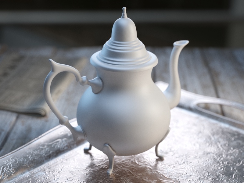
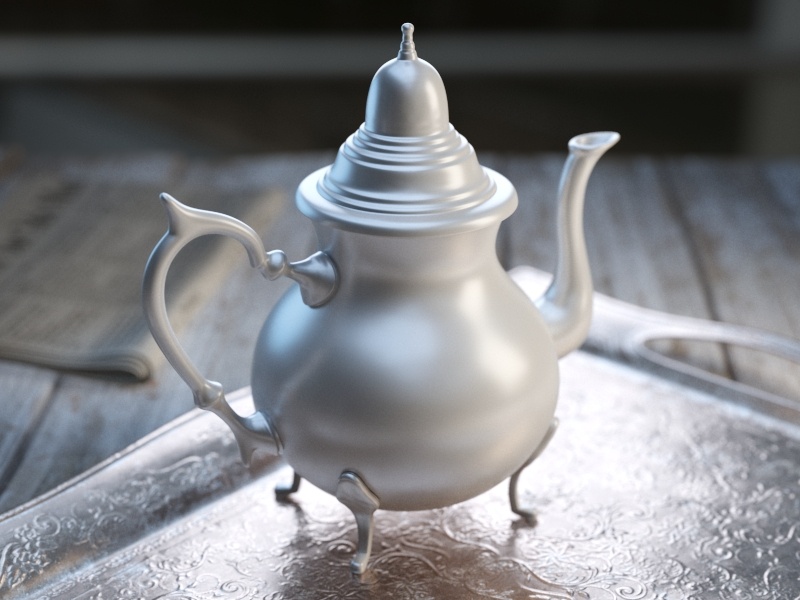
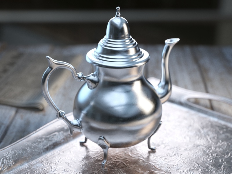
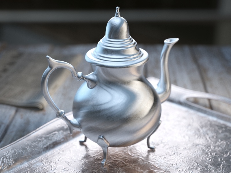
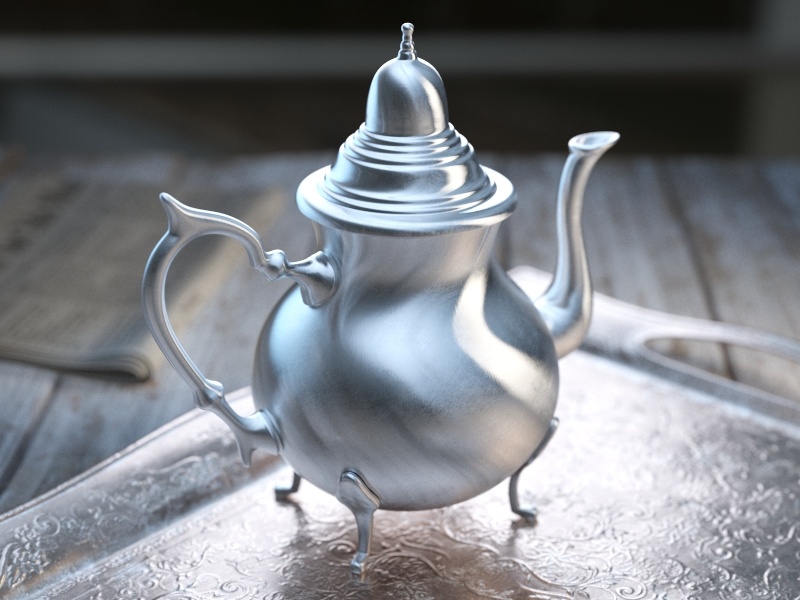
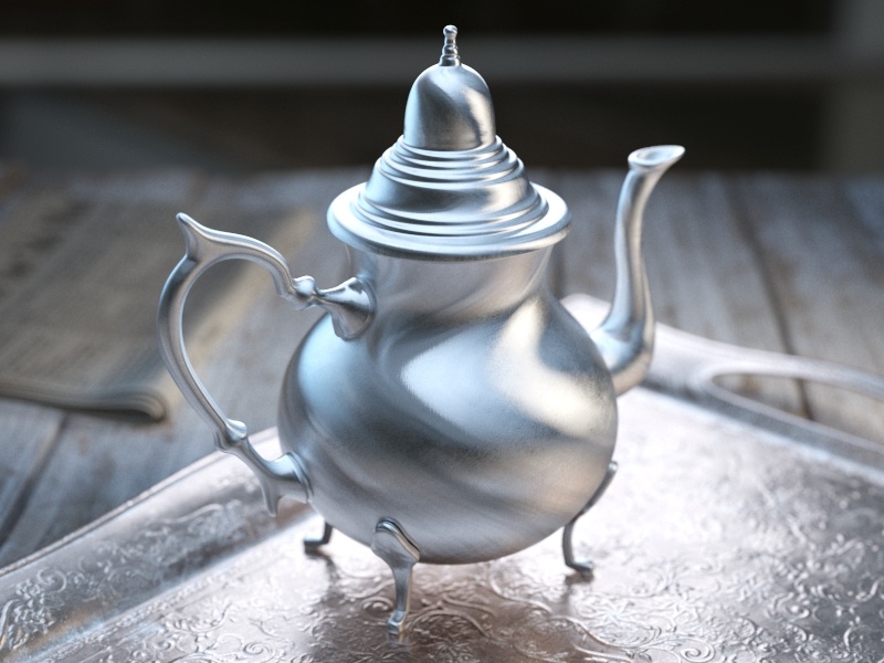
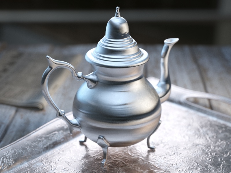
Example: Reflection Glossiness
This example demonstrates how the Glossiness parameter controls the highlights and reflection blurriness of the material. Fresnel IOR = 3.5.
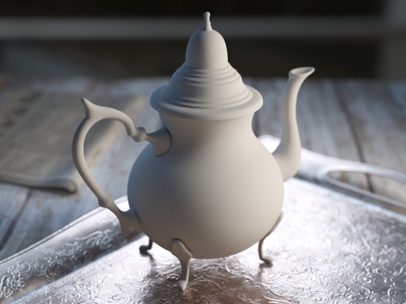
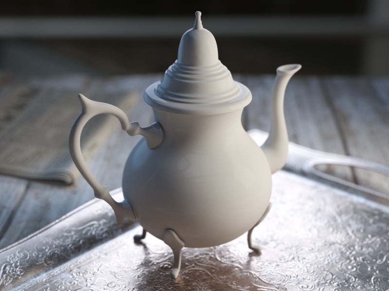
Example: Max Depth
This example demonstrates the effect of the reflection Max depth parameter.
Glossiness = 0.0

Glossiness = 0.1

Glossiness = 0.2

Glossiness = 0.3

Glossiness = 0.4
Glossiness = 0.5

Glossiness = 0.6
Glossiness = 0.7

Glossiness = 0.8
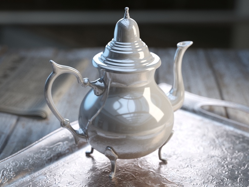
Glossiness = 0.9

Glossiness = 1.0

Reflection Max Depth = 1

Reflection Max Depth = 3

Reflection Max Depth = 5

Reflection Max Depth = 8

Reflection Max Depth = 10
Anisotropy
Anisotropy (-1..1) – Determines the shape of the highlight. A value of 0.0 means isotropic highlights. Negative and positive values simulate "brushed" surfaces. See the Anisotropy example for more information. A texture can be attached to this slot.
Anisotropy Rotation – Determines the orientation of the anisotropic effect in a float value between 0.0 and 1.0 (where 0.0 is 0 degrees and 1.0 is 360 degrees). See the Anisotropy example for more information. A texture can be attached to this slot.
UV Vectors Derivation – Specifies the method for deriving anisotropy axes:
Local object Axis – Uses a local axis for the anisotropy effect.
UV Space –
Anisotropy Axis – Specifies a local object axis for the anisotropy effect when UV Vectors Derivation is set to Local object axis.

Example: The Anisotropy and Rotation Parameters
This example demonstrates the effect of the Anisotropy and Anisotropy Rotation parameters, which determine the shape of the highlight. Type is set to Microfacet GTR (GGX).

Anisotropy = -0.8

Anisotropy = -0.6

Anisotropy = -0.4

Anisotropy = -0.2

Anisotropy = 0.0
Anisotropy = 0.2

Anisotropy = 0.4

Anisotropy = 0.6

Anisotropy = 0.8

Anisotropy Rotation = 0

Anisotropy Rotation = 0.1
Anisotropy Rotation = 0.2

Anisotropy Rotation = 0.3

Anisotropy Rotation = 0.4

Anisotropy Rotation = 0.5

Anisotropy Rotation = 0.6
Anisotropy Rotation = 0.7
Anisotropy Rotation = 0.8

Anisotropy Rotation = 0.9
Anisotropy Rotation = 1
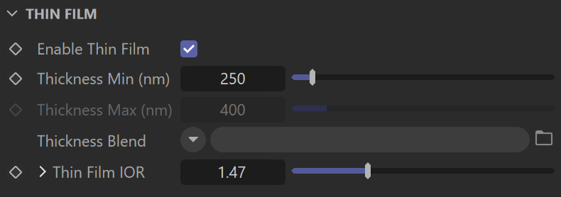
Thin Film
Enable Thin Film – Enables the Thin Film parameter.
Thickness Min (nm) – Determines the minimum thickness of the thin film in nanometers. If no Thickness Blend is applied, only this value is used for the thickness of the thin film. For more information, see the Thickness Min (nm) example.
Thickness Max (nm) – Determines the maximum thickness of the thin film in nanometers. This option is only available when Thickness Blend is applied.
Thickness Blend – Allows a map to be attached that blends the thickness values. If no map is applied, only the Thickness Min (nm) value is used to determine thickness.
Thin Film IOR – Specifies the reflective index of the thin film. A texture can be attached to this slot.
Texture – Specifies a texture file to be used for the Thin Film IOR.
Mix Strength – Specifies a blend amount for the texture map.
Mix Type – Specifies how the texture file is blended with the Thin Film IOR value. The texture is applied to a layer above the Thin Film IOR value.
Normal – When applied, the texture is blended normally. A Mix Strength of 100% makes the texture completely opaque, hiding the Thin Film IOR value below.
Add – When applied, the texture's value is added to the Thin Film IOR value.
Subtract – When applied, the Thin Film IOR value is subtracted from the texture's value.
Multiply – When applied, the texture is multiplied by the Thin Film IOR value.
Example: Thickness Min (nm)
This example shows how the Thickness Min (nm) parameter affects the V-Ray material, when no Thickness Blend is applied. The Thin Film IOR is set to 1.4.

Thickness Min (nm) = 0

Thickness Min (nm) = 300
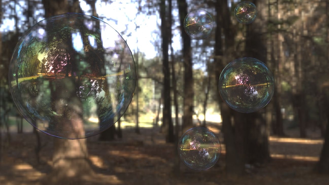
Thickness Min (nm) = 450
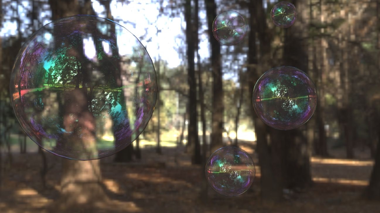
Thickness Min (nm) = 600
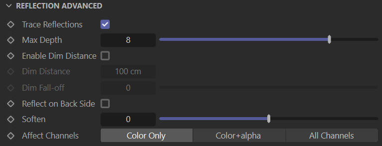
Reflection Advanced
Trace Reflections – Select this checkbox to enable reflections for the material.
Max Depth – The number of times a ray can be reflected. Scenes with lots of reflective and refractive surfaces may require higher values to look correct. See the Max Depth example above for more information.
Enable Dim Distance – Select this checkbox to stop tracing reflection rays after a specified Dim Distance.
Dim Distance – Specifies a distance, after which the reflection rays are not be traced.
Dim Fall-off – A falloff radius for the dim distance.
Reflect on Back Side – Select this checkbox to make V-Ray calculate the reflections on the back sides of objects, not only on the front.
Soften – Softens the edge of the BRDF at light/shadow transitions.
Affect Channels – Specifies which channels are affected by the reflectivity of the material.
Color Only – The reflectivity affects only the RGB channel of the final render.
Color+alpha – Causes the material to transmit the alpha of the reflected objects, instead of displaying an opaque alpha.
All channels – All channels and render elements are affected by the reflectivity of the material.
When selecting the Affect All channels option, be aware that the information of the respective component affects all render elements. In this case, the Beauty composition does not match the RGB result from the renderer.