This page describes the Environment Fog feature in V-Ray.
Overview
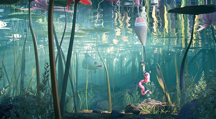
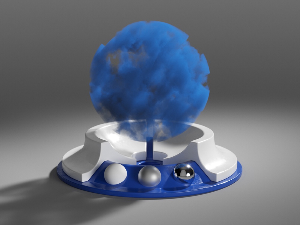
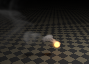
VRayEnvironmentFog is an atmospheric effect that allows the simulation of participating media like fog, atmospheric dust, and so forth. Volumetric properties can be determined by 3D texture maps. The atmospheric effect can also be confined to geometry objects.
VRayEnvironmentFog can use either of two algorithms to calculate volumetric lighting. The first algorithm is a simple exponential sampling scheme, which is used when there are no texture maps specified. In this mode, VRayEnvironmentFog takes a number of random points inside the volume and calculates the volumetric lighting at those points. The second algorithm is a raymarching scheme, which is used when any of the volume properties are mapped with a texture. In that case, VRayEnvironmentFog traverses the fog volume in small steps, calculates the volume properties at each step, and computes the volume lighting accordingly.
To set up a fog container, set the VRayEnvironmentFog as a volume material in the shading group for the container object. Set the Opacity of the surface material to black.
How to Set Up
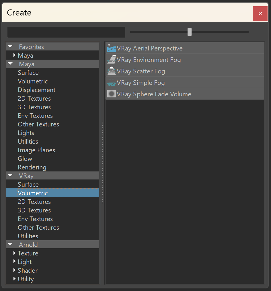
To set VRayEnvironmentFog, go to Render Settings > Overrides > Volumetrics.
Enable the Use environment volume option. Click Add New Item to add a volumetric map. You can add one or multiple maps. As an Environment Volume, select the VRayEnvironmentFog volumetric.
Multiple Environment Volumes are not supported on V-Ray GPU.
This is the default way of setting an environment fog in the scene.

Fog Gizmo
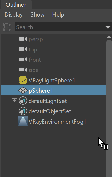
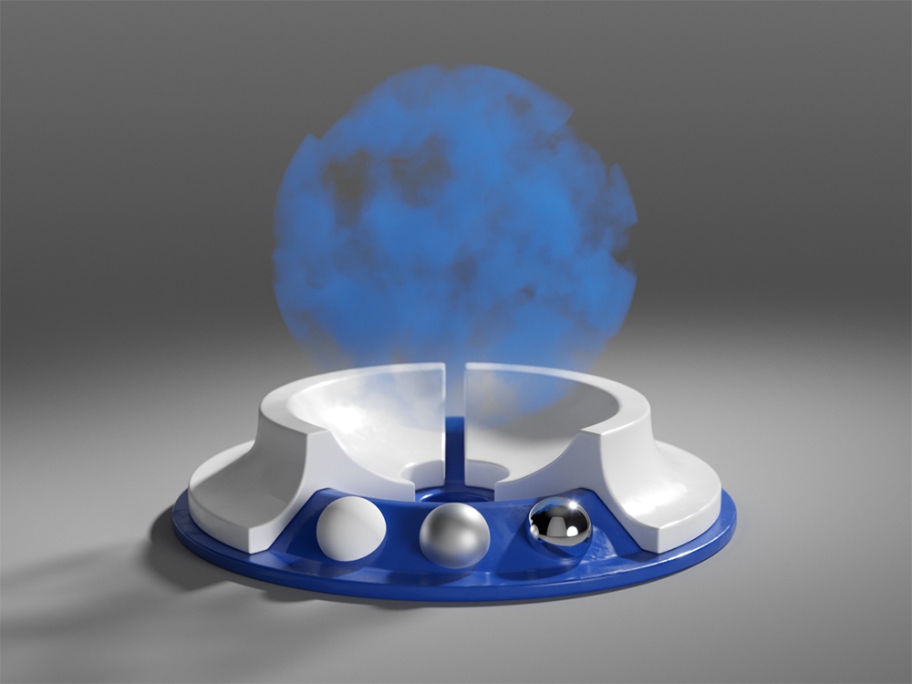
If you want to set an Environment fog gizmo, make the geometry object a member of the VRayEnvironmentFog set. You have to first set the VRayEnvironmentFog as global Environment volumetric as shown above.
This way the object becomes a constraint for the fog. The benefit of a fog gizmo is, a camera inside the gizmo renders the fog.
Fog Container
To create a fog container, create the geometry object first. Note that the VRayEnvironmentFog should not be set as an Environment volumetric!
Assign a V-Ray material that has opacity control. Here we use VRayMtl and make the object fully transparent by setting the Opacity Map to black color.
Go to the Shading Group of the material and as a Volume material, select the VRayEnvironmentFog.
Note that if the camera is set inside the fog container, the fog does not render.
Fog container is not supported with V-Ray GPU.
Lights
To make only certain light object(s) to affect the Environment Fog, navigate to the Outliner and make the selected light(s) a member of the Environment Fog set.
Set the Light Mode to either Override shape lights or Intersect with shape lights.

Common
Enabled – Enables or disables the VRayEnvironmentFog.
Color – Defines the color of the fog when it is illuminated by light sources. You can also use a texture map to drive the fog color. For more information, see the Color example below.
Emission – Controls the fog emission (self-illumination). You can use this parameter to substitute the ambient illumination inside the fog, instead of using GI. For more information, see the Emission example below.
Emission Multiplier – Multiplies the Emission parameter.
Phase Function – Controls how the light scatters inside the fog. Default value of 0.0 scatters the light uniformly in all directions. Positive value makes the light coming from a certain light source scatter mostly forward. Negative value results in it scattering backwards. See the Phase Function example below for more information.
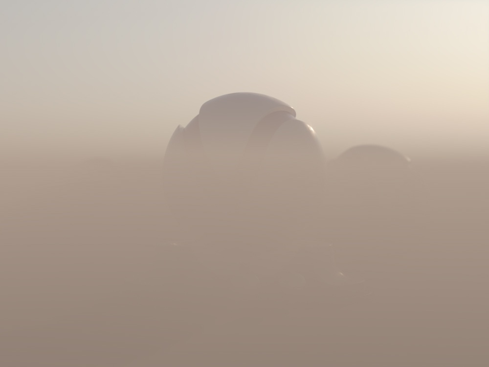
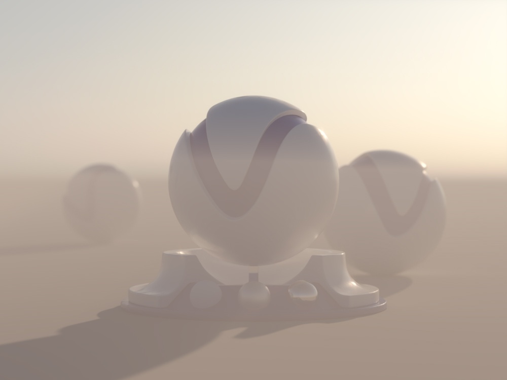
Fog Distance – Controls the fog density. Larger values make the fog more transparent, while smaller values make it denser. For more information, see the Fog Distance example below.
Fog Density – A multiplier for the Fog distance parameter. It allows a texture to be used for the density of the fog.
Transparency – Controls the color of the volumetric shadows and the tint for the objects seen through the fog. Brighter colors make the fog more transparent, while darker colors make it more dense at a distance given by the Fog distance parameter. See the Transparency example below and the How to create underwater shots with fog color transparency video for more information.
Fog Height – If the fog is not contained within a volume, it is assumed to start from a certain position along the scene's up-axis and continue downward indefinitely. This parameter determines the starting point along the up-axis. For more information, see the Fog Height example below.
When the fog is added to a gizmo, the Height parameter has no effect. When the fog is added to the environment or in a container, then the Height parameter determines the starting point in scene units.
See the How to Set Up section for more details on how to use the fog in a container, or a gizmo, or as an environment effect.
Light Mode – Allows you to specify which lights are considered when rendering the environment fog. It is used when you have certain lights affecting just specific objects in the scene while another group of lights is affecting the environment fog. Note that V-Ray GPU does not support light modes yet.
No lights – The lights in the scene do not affect the environment fog.
Use shape lights(default) – The lights attached to the environment fog set are ignored. Only the lights affecting the shape where the fog resides are used.
Override shape lights – Only the lights affecting the environment fog set are considered.
Intersect with shape lights – Only lights that are affecting both the shape and the environment fog set are considered.
Add to shape lights – Both lights that are affecting the shape and the environment fog set are considered.
For more information, see the Volumetric Caustics example below.
Ior – Index of Refraction for the volume, which describes the way light bends when crossing the material surface. A value of 1.0 means the light does not change direction.

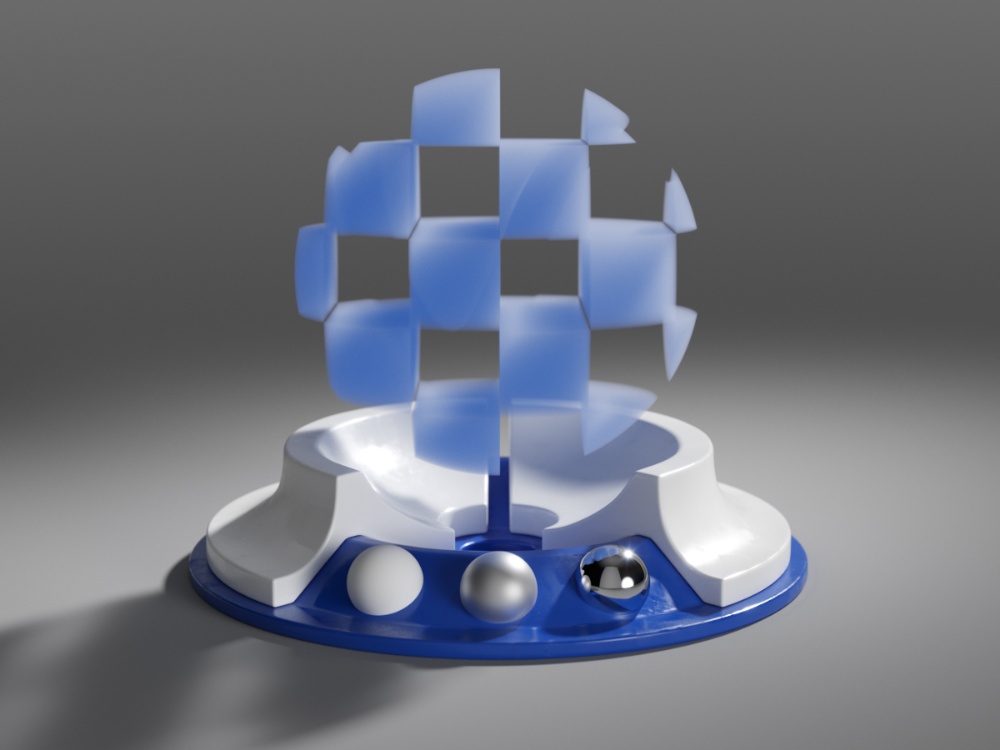
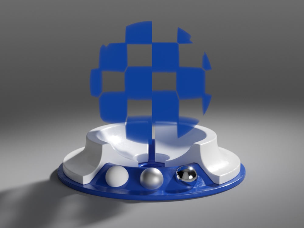
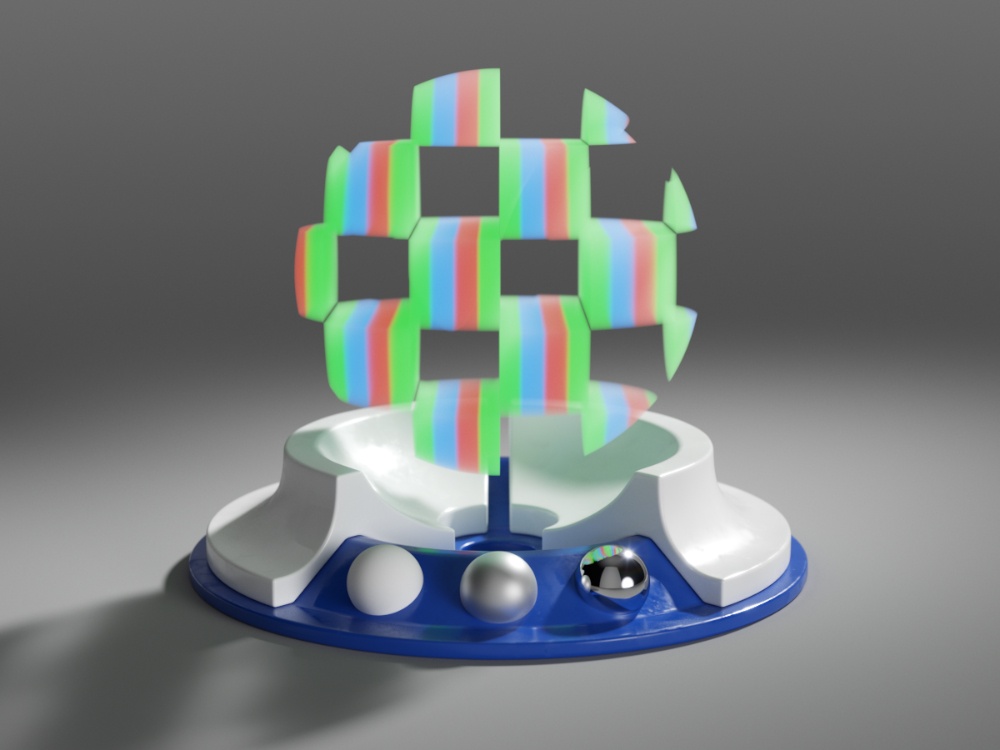
Example: Color
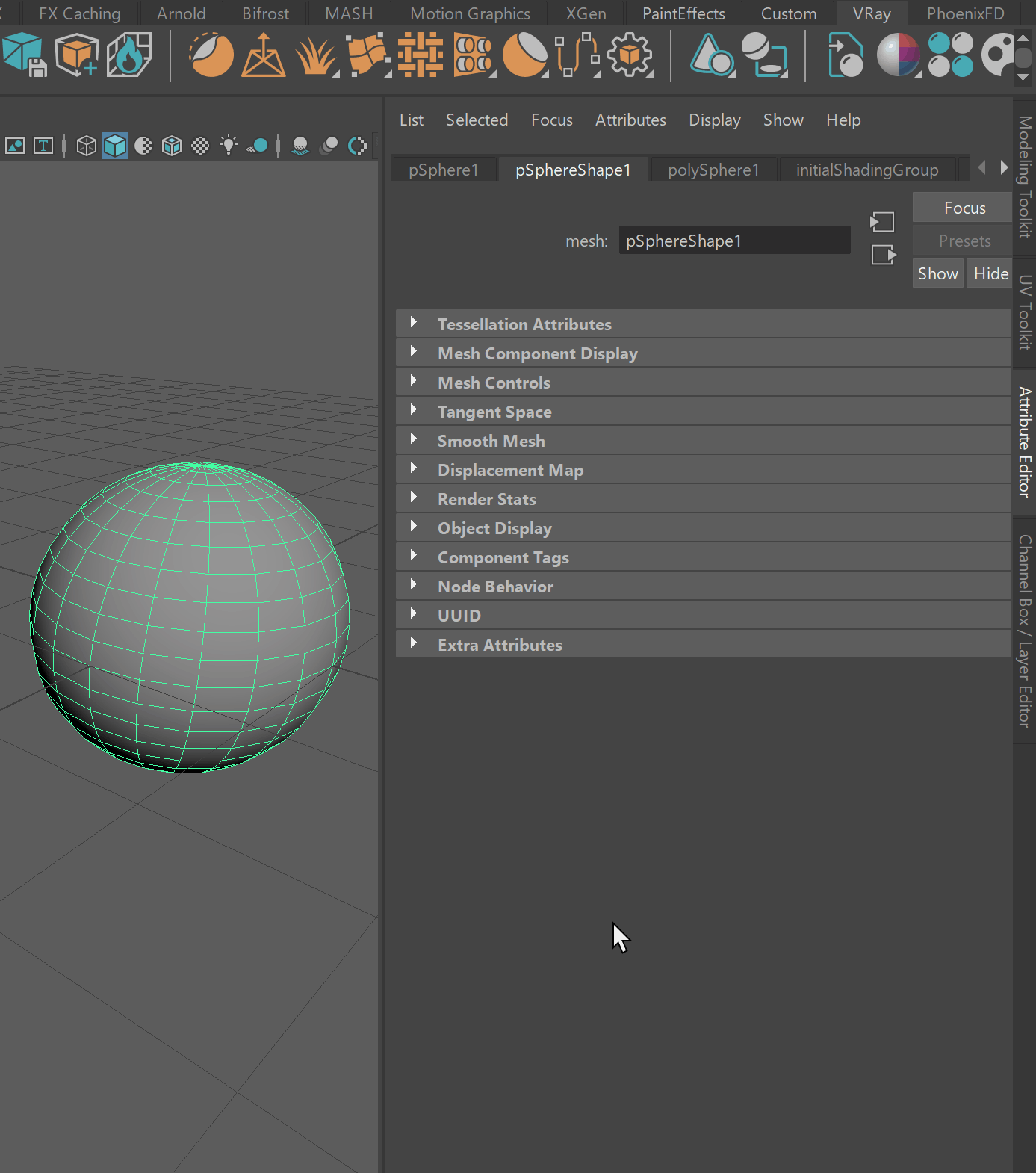
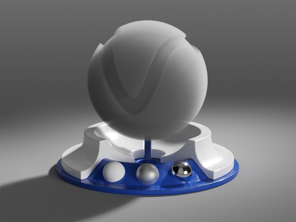
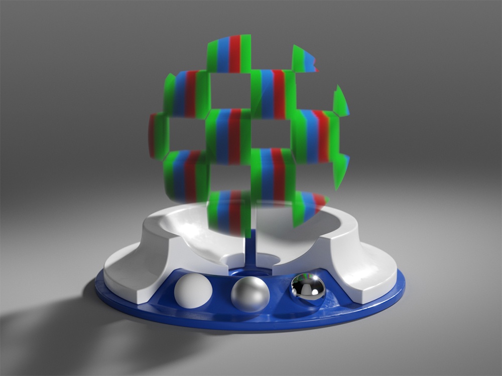
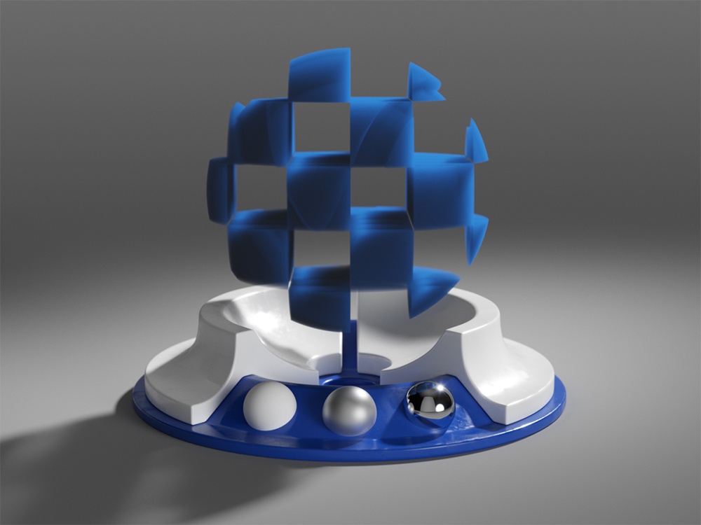
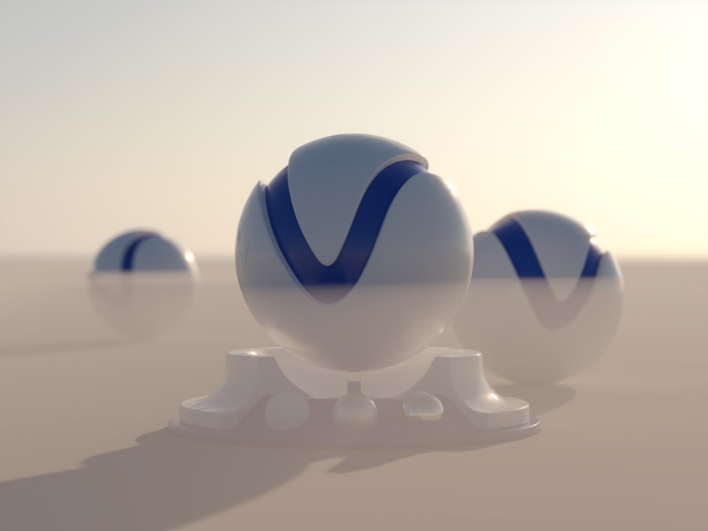
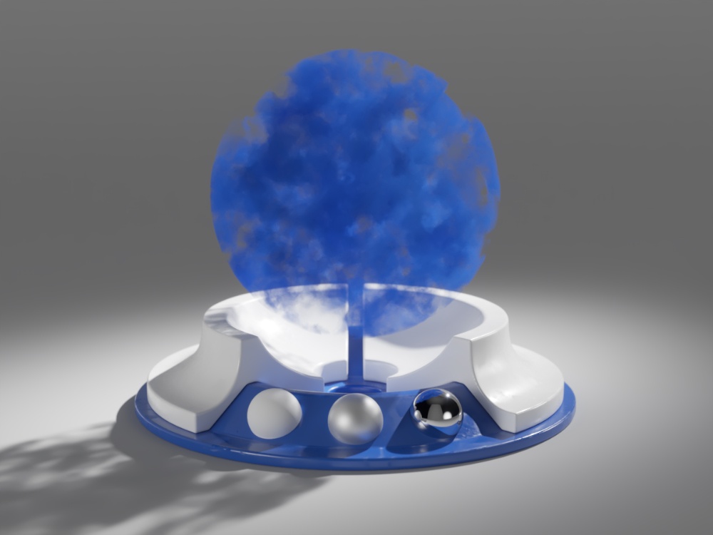
This example demonstrates the effect of the fog Color. Note how color only changes the way the volume reacts to light, and not the volume transparency. A sphere shaped as the V-Ray logo has been used to confine the fog volume with the VRayEnvironmentFog set as the Volume material in the shading group of the sphere. The opacity of the sphere's Surface material has been set to be 100 transparent by changing its Opacity Map to a black color. This means the Surface material has no contribution to the shading of the sphere, only the VRayEnvironmentFog material.
For the last 2 images, the fog Color has been mapped with a texture. The texture is plugged into a 3D projection node with the gizmo wrapping the object.
fog color = white

fog color = green
A Gradient Ramp texture with Solid interpolation.
The fog density is mapped with a checker texture.

A Noise texture with Turbulence type
Move the slider to see the example renders.
Example: Phase Function
This example uses back lighting and the Scatter GI is turned on with 1 bounce.

Fog phase function = -0.75

Fog phase function = 0

Fog phase function = 0.75
Move the slider to see the example renders.
Example: Fog distance
This example demonstrates the effect of the Fog distance parameter. Note how larger values make the fog more transparent. A sphere shaped as the V-Ray logo has been used to confine the fog volume with the VRayEnvironmentFog set as the Volume material in the shading group of the sphere. The opacity of the sphere's Surface material has been set to be 100 transparent by changing its Opacity Map to a black color. This means the Surface material has no contribution to the shading of the sphere, only the VRayEnvironmentFog material.
Fog distance is 0.1
Fog density is mapped with a noise texture
Fog distance is 0.5
Fog density is mapped with a noise texture
Fog distance is 2.5
Fog density is mapped with a noise texture

Fog distance is 0.5
No texture in the fog density
Fog distance is 0.5
Fog density is mapped with a checker texture
Move the slider to see the example renders.
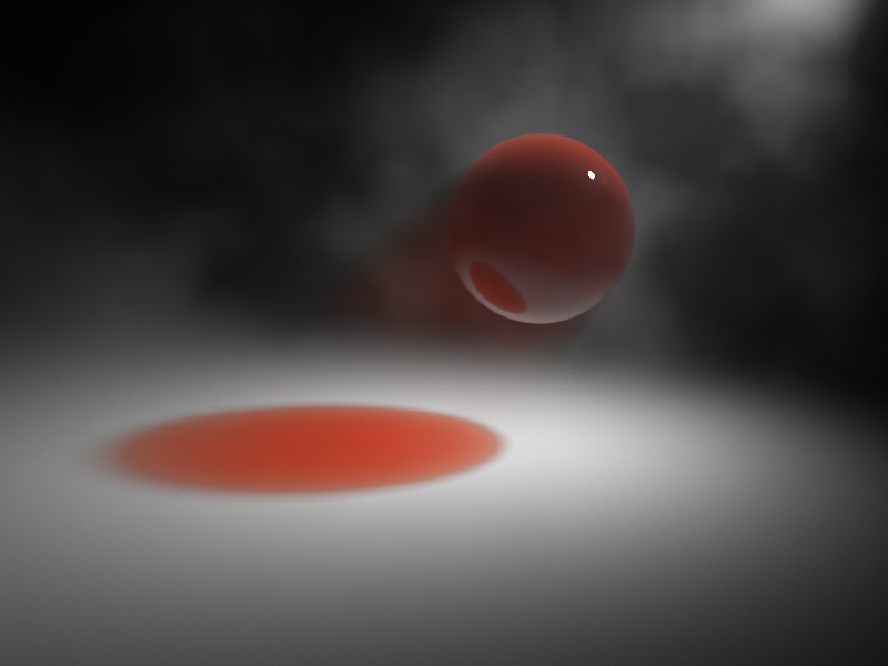
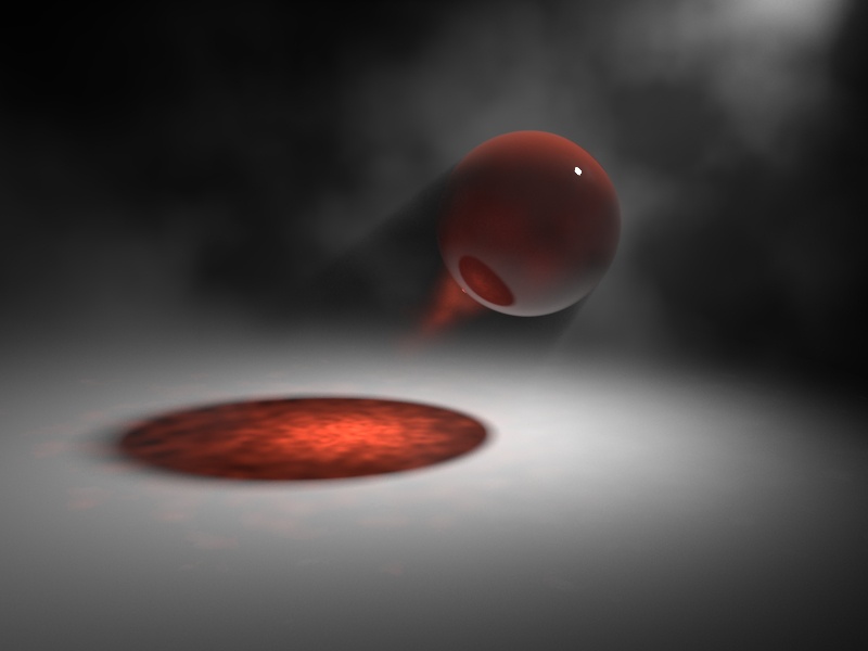
Examples: Transparency
This example demonstrates the effect of Fog transparency parameter. Note how the objects inside the fog are tinted and the transparency of the fog is affected, while the Fog distance parameter remains unchanged.
![]()
Fog transparency = default HSV (0, 0, 46)
![]()
Fog transparency = HSV (0, 0, 96)
![]()
Fog transparency = HSV (0, 0, 146)
![]()
Fog transparency = HSV (158, 125, 145)
![]()
Fog transparency = HSV (24, 82, 124)
Move the slider to see the example renders.
How to create underwater shots with fog color transparency
See the video to learn how to prepare the fog distance, set the fog colored transparency, and use V-Ray distance texture for finer control.
First, prepare your fog distance by setting the visibility range of the fog. Then, set the fog color transparency. You can also tweak the absorbed transparency color, if needed.
Add a fog transparency texture - a V-Ray distance texture is used for fine control.
Example: Emission
This example demonstrates the effect of the Emission parameter. The Fog color is gray so as to better show the effect of the emission. Note that since we also have GI enabled, the fog emission causes the volume to illuminate both itself and other objects around it. The fog density is mapped with a Checker texture. A sphere shaped as the V-Ray logo has been used to confine the fog volume with the VRayEnvironmentFog set as the Volume material in the shading group of the sphere. The opacity of the sphere's Surface material has been set to be 100 transparent by changing its Opacity Map to a black color. This means the Surface material has no contribution to the shading of the sphere, only the VRayEnvironmentFog material.
In the last two renders, the Emission has been mapped with a texture. The Color is gray to better show the light scattering inside the volume, produced by the global illumination.
Fog emission is black (no emission),
Fog color is gray
Fog emission is dark blue,
Fog color is gray
Fog emission is dark blue, Fog color is black
(only the fog emission affects the image)
Fog emission is mapped with a Gradient Ramp texture
Fog color is gray

Fog emission is mapped with a red Noise texture with Turbulence type
Fog color is gray
Move the slider to see the example renders.
Example: Fog height
When there are no geometry nodes connected to VRayEnvironmentFog, the volume occupies space downward from a certain height along the scene's up-axis, determined by the Fog height parameter. The following examples demonstrate this. Note that as the Fog height is increased, the scene becomes darker - this is because the sun is blocked by a larger amount of fog. This can be corrected by increasing the Fog distance parameter and thus making the fog more transparent. Note also the sudden decrease of brightness when the camera is included inside the fog volume.

Fog distance = 0
Fog height = 0

Fog distance = 50
Fog height = 10
Fog distance = 50
Fog height = 15
Fog distance = 50
Fog height = 20

Fog distance = 50
Fog height = 50
Move the slider to see the example renders.
Fog distance = 0
Fog height = 0

Fog distance = 200
Fog height = 10
Fog distance = 200
Fog height = 15
Fog distance = 200
Fog height = 20

Fog distance = 200
Fog height = 50
Move the slider to see the example renders.
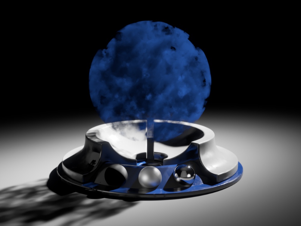
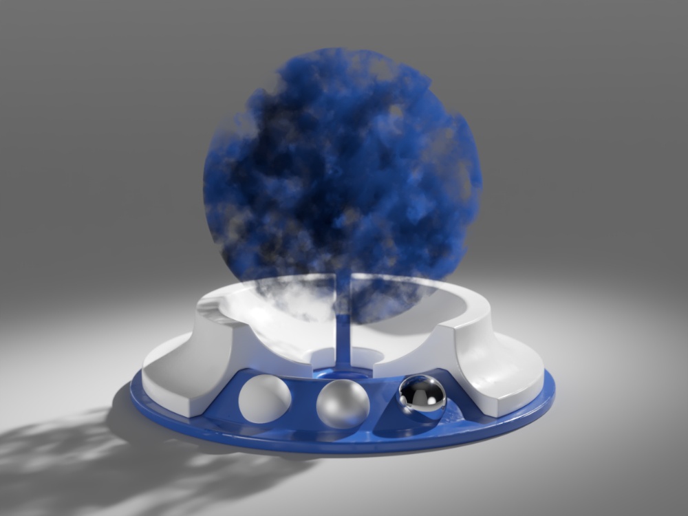
Example: Volumetric Caustics
This example demonstrates volumetric caustics and colored shadows with different settings.
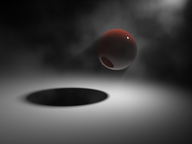
Caustics are off, Affect shadows for the sphere material is off
Caustics are off, Affect shadows for the sphere material is on

Caustics are on

Caustics are on, and the Fog density is mapped with a Smoke texture
Move the slider to see the example renders.
The quality of the volumetric caustics depends on the sampling of the volume fog, on the V-Ray caustics settings, and the caustics settings for the light. In both images below, all parameters are same with the exception of the caustics subdivs for the light in the light settings dialogue. Note how the more photons are shot, the more defined the caustics are. In this example, we also have the caustics Max. density parameter set to 0.3 in order to limit the photon density in the caustics map. This saves memory and makes the rendering faster, although it limits the spatial resolution of the caustics (in our case, to 0.3 scene units).
Compare the two examples where the light has 1000 Caustics subdivs (500,000 caustics photons are shot) and 200 Caustics subdivs (20,000 caustics photons are shot).
Note the broken caustics beam in the example with 1000 Caustics subdivs - this is not because there are not enough caustics photons, but because we don't have enough samples for the fog itself.

GI (Indirect illumination)
Scatter GI – When enabled, the fog also scatters global illumination. Note that this can be quite slow. In many cases, global illumination within the fog can be substituted with a simple emission term. When this option is enabled, the currently selected global illumination algorithm in the V-Ray settings are used to accelerate GI inside the volume (e.g. the light cache or brute-force). For more information, see the Scatter GI and Scatter bounces example and the Importance of GI example below.
Scatter bounces – When Scatter GI is enabled, this controls the number of GI bounces that are calculated inside the fog.

Example: Scatter GI and Scatter bounces
This example demonstrates the effect of the Scatter GI and Scatter bounces parameters. Note how multiple scattering of light inside the volume greatly increases the realism of the image.
GI is off in the V-Ray settings;
The fog volume only shows direct lighting
GI is on, Scatter GI is off.
The fog does not scatter GI and so looks identical to the left image (it is lit with direct light only).

GI is on, Scatter GI is on, Scatter bounces is 1.
Notice how the fog volume is affected by the skylight. Brute Force was used for the primary GI engine.

GI is on, Scatter GI is on, Scatter bounces is 2.
Brute Force + Light Cache GI for secondary bounces
GI is on, Scatter GI is on, Scatter bounces is 4.
Brute Force + Light Cache GI

GI is on, Scatter GI is on, Scatter bounces is 8.
Brute Force + Light Cache GI

GI is on, Scatter GI is on, Scatter bounces is 100.
Brute Force + Light Cache GI
Move the slider to see the example renders.
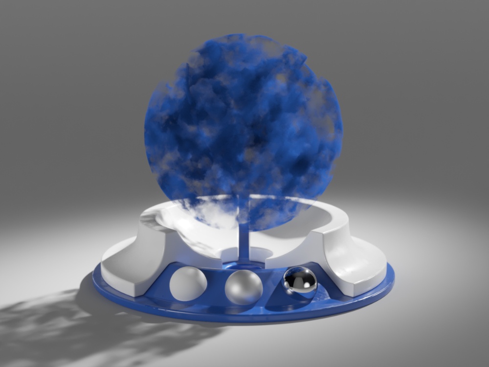
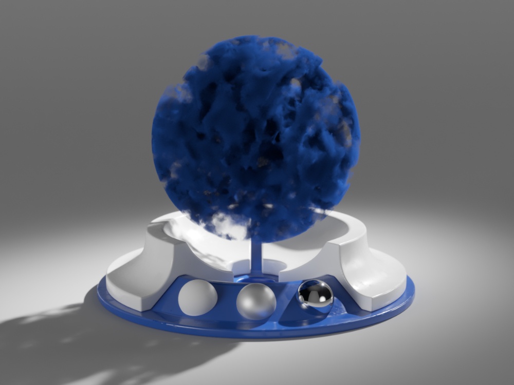
Example: Importance of GI
GI scattering is especially important when creating cloud-like volumes. For example, compare the following two images, done with and without GI scattering.
Global illumination is off
 Global illumination is on with Scatter GI on and Scatter bounces set to100
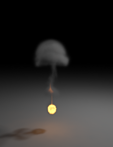
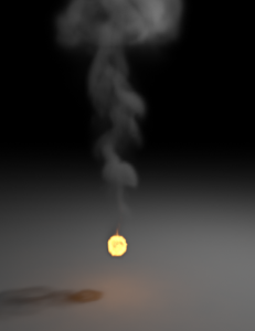
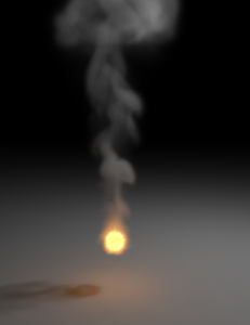
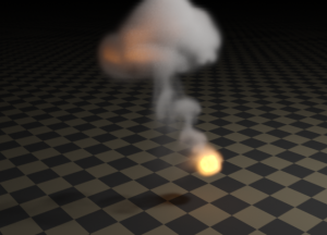
The following example shows GI scattering inside a smoke volume. The volumetric textures (density and emission) for this example are provided from a fluid dynamics simulation in the form of 3D textures. Note how GI scattering causes the smoke to be naturally illuminated by the fire in the second row of images.


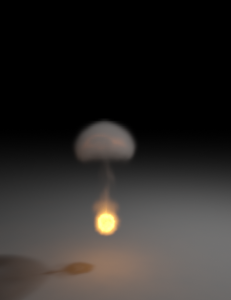
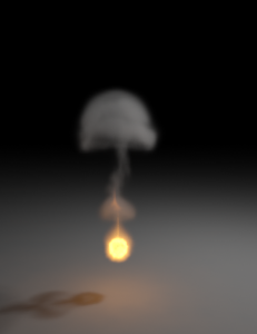
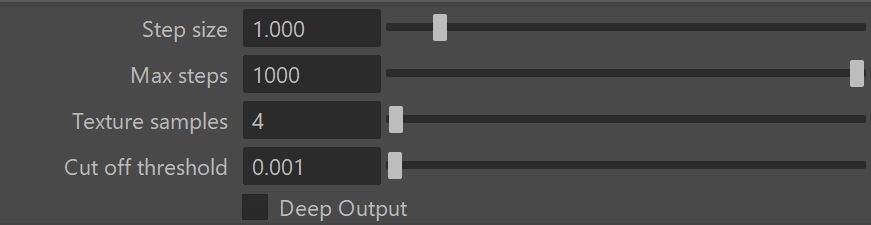
Raymarching
This sampler is used when any of the fog properties (color, density or emission) is mapped with a 3d texture. The sampler steps through the volume, evaluating volumetric textures and lighting, until it leaves the volume (if the fog is contained within a volume), or until the accumulated volume transparency falls below a certain cut-off threshold, or until a specified number of maximum steps is reached.
Step size – Determines the size of one step through the volume. Smaller steps produce more accurate results but are slower to render. In general, dense volumes require smaller step sizes than more transparent volumes. In practice, step sizes that are two to three times smaller than the Fog distance parameter work well. Step size is calculated in scene units.
Max steps – Specifies the maximum number of steps through the volume.
Texture samples – Determines the number of texture samples for each step through the volume. This samples textures more accurately than the volumetric lighting. It is useful in cases where the textures vary much faster than the lighting itself (e.g. for detailed fractal textures). For more information, see the Texture samples with Ray marching example below.
Cut off threshold – Controls when the raymarcher stops traversing the volume. If the accumulated volume transparency falls below this threshold, the volume is considered opaque and tracing is aborted. Higher values make the rendering faster but may introduce artifacts. This parameter is not available when the render engine is set to CUDA.
Deep Output – Toggles writing deep data to the file. Note that enabling this option forces ray marching even for simple volumetrics which can cause slower rendering.
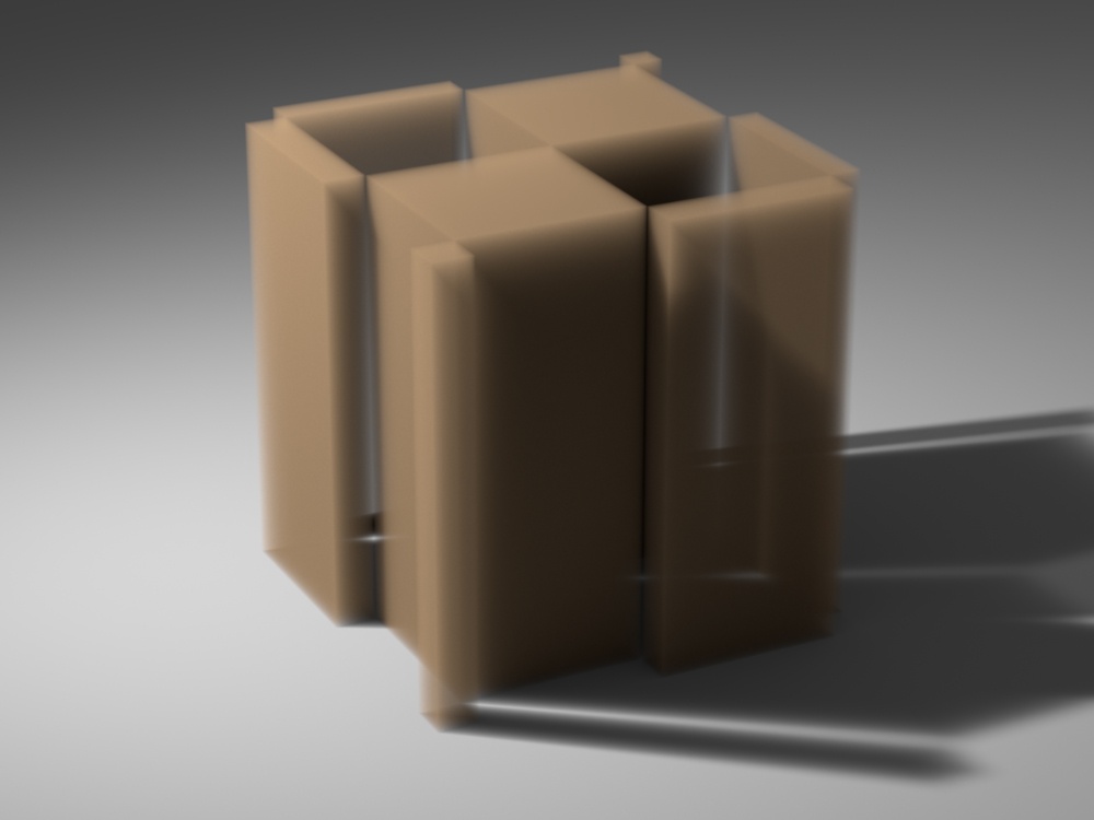
Example: Step size with ray marching
When any of the parameters (density, color or emission) is mapped with a texture, VRayEnvironmentFog uses a raymarching algorithm to compute the intersection of a ray with the volume.
The following examples demonstrate the effect of the Step size parameter. A Box is used to confine the volume, and the density is mapped with a Checker texture. Note how smaller values cause less noise and smoother shading of the volume. Note also that denser volumes require smaller values of the Step size parameter in order to produce a smooth result compared to more transparent volumes. In general, values for the Step size that are 2 to 3 times smaller than the Fog distance parameter work okay in most cases.
Step size is 0.1
Fog distance = 5.0

Step size is 0.5
Fog distance = 5.0
Step size is 1.0
Fog distance = 5.0
Step size is 2.5
Fog distance = 5.0

Step size is 5.0
Fog distance = 5.0

Step size is 10.0
Fog distance = 5.0

Step size is 0.4
Fog distance = 20.0

Step size is 2.0
Fog distance = 20.0
Step size is 4.0
Fog distance = 20.0
Step size is 10.0
Fog distance = 20.0

Step size is 20.0
Fog distance = 20.0
Step size is 40.0
Fog distance = 20.0
Move the slider to see the example renders.
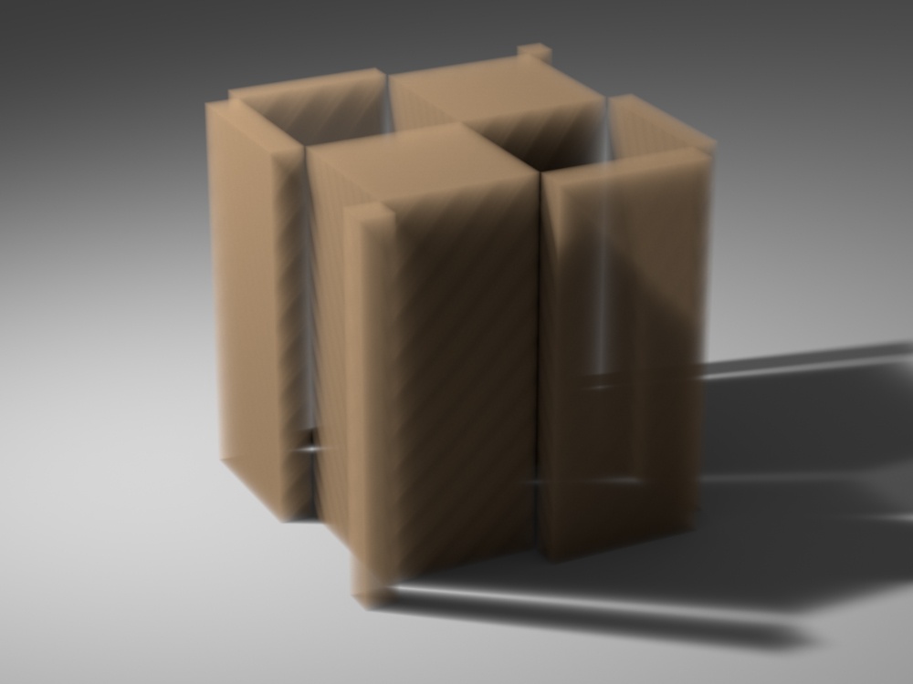
Example: Texture samples with ray marching
The following example demonstrates the effect of the Texture samples parameter. This parameter allows for more accurate sampling of textures with rapid changes, without the need to increase the Step size parameter, and thus saving render time.
Texture samples is 1, Step size is 4.0

Texture samples is 4, Step size is 4.0
Texture samples is 1, Step size is 1.0
Move the slider to see the example renders.
Fade Out
Fade out mode – Allows you to choose between two different modes of fade out.
Fade out radius – Allows you to set a radius for the fade out of the fog.
Per Object Fade Out Radius – When enabled, the fade out effect is applied to each fog volume independently using the Fog Fade Out Radius Extra V-Ray Attribute.

Ray Filter
Affect background – Enables or disables the tracing of background rays through the volumetric.
Affect Alpha – Enables or disables the tracing of Alpha rays through the volumetric.
Affect reflection rays – Enables or disables the tracing of reflection rays through the volumetric.
Affect refraction rays – Enables or disables the tracing of refraction rays through the volumetric.
Affect shadow rays – Enables or disables the tracing of shadow rays through the volumetric.
Affect GI rays – Enables or disables the tracing of GI rays through the volumetric.
Affect camera rays – Enables or disables the tracing of Camera rays through the volumetric.

Notes
- When using VRayEnvironmentFog with weak VRayLights, it may be necessary to turn down the Cut-off threshold parameter of the lights. The default value for this parameter works fine for surfaces, but for volumes, where a lot of weak light contributions are added together, it may produce a visible sharp boundary where the light calculations stop.
- You can use the various procedural textures to modify volume properties.
- V-Ray does not have separate global illumination maps for volumetric rendering. Instead, all GI engines (the irradiance map, light cache, global/caustics photon maps) have been modified to support volumetric data.
- V-Ray GPU render does not support Mapping options yet.
- V-Ray GPU render does not support IOR attribute yet.
- To use a fog container with CUDA, first add the fog as a Volumetric override, then add the shape to the fog set.
- Probabilistic volumetrics make textured fog shading much faster, but also it can result in noisier renders with low sample counts.
- There is a slight difference between renders containing textured fog with version 5 and version 6. The discrepancy can be fixed by lowering the Step size parameter.