This page provides information on the V-Ray Mesh Light.
Overview
The VRayLightMesh can create light sources that have volume and shape without the need to use self-illuminated objects and global illumination.
If the VRayLightMesh is close to other surfaces in the scene, it is best to use it with GI enabled so V-Ray can use combined direct and GI sampling of the mesh light. Without GI, the light might produce noisy results for surfaces that are very close to it.
In order to use VRayLightMesh properties with LightSelect render element, add the vrayLightMeshProperties_lightlink node to the LightSelect node.

Image courtesy of Leticia Reinaldo Gillett
||V-Ray Shelf|| > (Right-click) Assign Mesh Light Properties icon > Turn selection into lights

||V-Ray menu|| > Lights > V-Ray Mesh Light

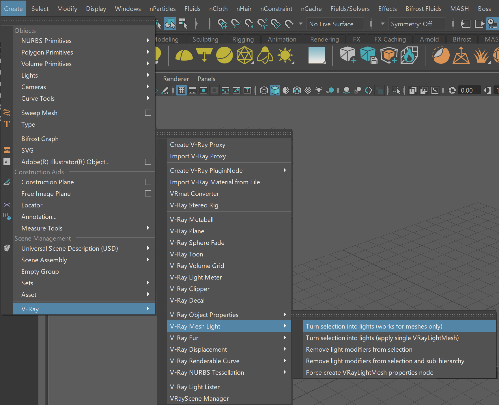
||Create menu|| > V-Ray > Mesh lights > Turn selection into lights
Basic Parameters
Enabled – Determines whether or not the VRayLightMesh will emit light in the scene.
Color Mode – Sets the mode in which the color of the light will be specified.
Light Color – The color of the light. When using photometric units, this color is normalized so that only the color hue is used, whereas the light intensity is determined by the Intensity Multiplier.
Temperature – Controls the color of the light, when the Color Mode is set to Temperature.
Intensity multiplier – A multiplier for the light color; this is also the light intensity in the units chosen by the Units parameter.
Units – Using correct units is essential when you are working with the Physical camera Attributes. Note that when changing these units, the Intensity multiplier value is not converted to match the lighting and uses the same amount for all different units. The possible values are:
default – The color and multiplier directly determine the visible color of the light without any conversion. The light surface will appear with the given color in the final image when seen directly by the camera (assuming there is no color mapping involved).
Lumens – Total emitted visible light power measured in lumens. When this setting is used, the intensity of the light will not depend on its size. A typical 100W electric bulb emits about 1500 lumens of light.
lm/m/m/sr – Visible light surface power measured in lumens per square meter per steradian. When this setting is used, the intensity of the light depends on its size.
Watts – Total emitted visible light power measured in watts. When using this setting, the intensity of the light does not depend on its size. Keep in mind that this is not the same as the electric power consumed by the light source (by a light bulb, for example). A typical 100W light bulb only emits between 2 and 3 watts as visible light.
w/m/m/sr – Visible light surface power measured in watts per square meter per steradian. When this setting is used, the intensity of the light depends on its size.

Texture
Use Texture – Allows the light to use a texture for its surface. If there are surfaces which are close to a texture-mapped light, it is best to have GI enabled. This allows V-Ray to use combined direct and indirect sampling for the light, reducing the noise for surfaces close to the light.
Texture – Specifies the texture to use. Note: If an RGBA texture file (a file that contains an alpha channel) is used, the file's alpha output must be connected to the Texture Alpha attribute to utilize the alpha channel on the light.
Texture Alpha – A multiplier for the texture's alpha channel. Note: The default value of 1 (fully opaque) remains unchanged whenever a file texture is connected to the Texture attribute, even if that file contains an alpha channel. For a file's alpha channel to be utilized, it's alpha output needs to be connected to this attribute.
Cache Texture – When enabled, V-Ray will sample the texture and produce a lower resolution one to be used for the lighting. This greatly speeds up the rendering of mesh lights with textures.
These parameters are not supported when working with the V-Ray GPU render.

Options
Double Sided – Controls whether light is emitted from both sides of each face. For more information, see the Single-Sided vs. Double-Sided Lights example below.
Invisible – Controls whether the shape of the VRayLightMesh source is visible in the render result. When this option is turned off the source is rendered in the current light color. Otherwise, it is not visible in the scene. Note that this option only affects the visibility of the light when seen directly by the camera or through refractions. The visibility of the light with respect to reflections is controlled by the Affect specular and Affect Reflections options. See the Invisibility example below.
Occlude Other Lights – Controls the behavior of invisible lights in relation to other light sources. When enabled, the light blocks the lighting from other lights as if it's visible. Also in reflections the light behaves as it's visible and occludes other lights. When disabled, the light is transparent for other lights and does not occlude them. This option doesn't affect visible lights (as they always occlude other lights) and dome lights (which are always additive).
Affect Diffuse – Determines whether the light is affecting the diffuse properties of the materials.
Affect Specular – Determines whether the light is affecting the specular of the materials. This means glossy reflections.
Affect Reflections – Determines whether the light will appear in reflections of materials. This means both perfect and glossy reflections.
Affect Atmospherics – When enabled, the light influences the atmospheric effects in the scene.
Diffuse contribution – A multiplier for the effect of the light on the diffuse.
Specular contribution – A multiplier for the effect of the light on the specular.
Atmospherics contribution – Determines the amount of influence the light has on the atmospheric effects such as VRayEnvironmentFog, VRayVolumeGrid or Phoenix effects.

Example: Invisibility
The example below shows the difference between an invisible mesh light and visible mesh light.


Example: Double-Sided Lights
This example shows the difference between the Double-Sided option enabled and disabled.


Sampling
Light cut-off threshold – Specifies a threshold for the light intensity, below which the light will not be computed. This can be useful in scenes with many lights, where you want to limit the effect of the lights to some distance around them. Larger values cut away more from the light; lower values make the light range larger. If you specify 0.0, the light will be calculated for all surfaces. This parameter is not available when the renderer is set to V-Ray GPU.
Override motion blur samples – Overrides the default number of samples that will be used to sample the current light for motion blur.
Motion blur samples – When the Override motion blur samples parameter is enabled this value will be used when sampling the motion blur created by the current light.
Texture Resolution – Specifies the resolution at which the texture is cached.

Shadows
Shadows – When enabled (the default), the light casts shadows. Turn this option off to disable shadow casting for the light.
Shadow bias – Moves the shadow toward or away from the shadow-casting object (or objects). Higher values move the shadow toward the object(s) while lower values move it away. If this value is too extreme, shadows can "leak" through places they shouldn't or "detach" from an object. Other effects from extreme values include Moire patterns, out-of-place dark areas on surfaces, and shadows not appearing at all in the rendering.
Shadow Color – Controls the color of shadows for this light. Note that anything different from black is not physically correct. This options is inactive when using the V-Ray GPU engine.

Decay
The Decay parameters determine how the light fades in and out. The Near decay determines how light fades in. The light isn't at its maximum value at its source, but instead gradually increases until it reaches the Near end. The Far decay determines how light fades out. The light isn't at its maximum value at its end, but instead gradually decreases after the Far decay start.
Decay option is useful for creating hotspots or controlling the length of a "God Rays" effect created with Environment Fog.

Near decay on – Toggles near decay on and off. See the Near decay examples below for more information.
Near decay start – Determines where the fade in starts. Anything before this point is rendered dark.
Near decay end – Determines where the fade in ends. After this threshold, the light is at its full value.
Far decay on – Toggles far decay on and off. See the Far decay examples below for more information.
Far decay start – Determines where the fade off starts.
Far decay end – Determines where the light reaches a value of 0, i.e. completely fades off.

Example: Near Decay Start
This example shows the variances achieved by changing the Near decay start parameters only.

Near decay start 10, Near decay end 60

Near decay start 30, Near decay end 60

Near decay start 50, Near decay end 60
Example: Near Decay End
This example shows the variances achieved by changing the Near decay end parameters only.

Near decay start 0, Near decay end 10

Near decay start 0, Near decay end 30

Near decay start 0, Near decay end 50
Example: Far Decay Start
This example shows the variances achieved by changing the Far decay start parameters only.

Far decay start 10, Far decay end 60

Far decay start 30, Far decay end 60

Far decay start 50, Far decay end 60
Example: Far Decay End
This example shows the variances achieved by changing the Far decay end parameters only.

Far decay start 60, Far decay end 60

Far decay start 60, Far decay end 100

Far decay start 60, Far decay end 120
Example: Near and Far Decay
This example shows some artistic lighting results achieved by using both Near and Far decay options.

Near decay start 0, Near decay end 15, Far decay start 30, Far decay end 60

Near decay start 20, Near decay end 35, Far decay start 40, Far decay end 55

Near decay start 30, Near decay end 60, Far decay start 90, Far decay end 120
Photon Emission
This rollout is inactive when using the V-Ray GPU engine.
Caustics subdivs – Used by V-Ray when calculating Caustics . Lower values mean more noisy results, but will render faster. Higher values produce smoother results but take more time.
Caustics multiplier – A multiplier for the generated caustics by the selected light. Note that this multiplier is cumulative; it does not override the multiplier in the Caustics rollout in the Render Settings window.

Notes
- Each VRayLightMesh that you create has a corresponding VRayLightMeshLightLinking node created that has the name vrayLightMeshProperties_lightlink. You can use this node to perform light linking on the VRayLightMesh.