This page contains information on the Layers panel in the new V-Ray Frame Buffer.
Overview
The Layers panel in New V-Ray Frame Buffer provides a new powerful workflow for making adjustments to your rendered image. Bring out render elements and compose them together with individual color corrections in the panel's Composite mode, or deconstruct light contribution in the scene and fine-tune each light individually in the completed render using the VRayLightMix mode. Correct the final render just like you were able to do in the previous version of VFB.
UI Path
||V-Ray Frame Buffer|| > Layers

Layers Menu
Creates a layer or folder. Multiple layers of the same type can be added.


| Creates a layer or folder. Multiple layers of the same type can be added. Folder – Allows grouping multiple layers in folders and folders in sub-folders. |
| Deletes the selected layer(s). |
| Saves a layer tree preset. |
| Loads a layer tree preset. |
| Quick access to the Layer/Filter Presets. |
| Undo various actions related to layers such as create, delete, reorder or modify a layer. |
| Redo various actions related to layers such as create, delete, reorder or modify a layer. |


Command | Description |
|---|---|
| Reset | Resets all changes done to the selected layer. |
| Save | Saves the layer as a preset. |
| Load | Loads a preset for the selected layer. |
| Delete | Deletes the selected layer. |
| Save as LUT | Bakes all the color corrections to a LUT file. |
| New Layer | Creates a new layer. |
| Duplicate | Duplicates the selected layer. |
| Blend Modes | Specifies how the selected layer blends with the result from all layers below it. |
Color correction layers like Exposure and White Balance are applied to a single layer instead of the entire composite.
Selecting a layer and then add a new correction or drag the correction layer to another layer until an arrow icon appears.
The Display Correction, Sharpen/Blur, Denoiser, Lens Effects and Source layers are listed in the Layers panel by default to any rendered image. Their order cannot be changed.
Layers can be disabled from the visibility icon (![]() ), reordered, nested, stacked in folders, etc. Disabled layers are indicated by the
), reordered, nested, stacked in folders, etc. Disabled layers are indicated by the ![]() icon.
icon.
Corrections are applied from the bottom to the top, except for nested layers, which are executed after their parent.
Color corrections and the denoiser channel are saved in the output image just like they are applied in the VFB.
Adjustments made to the Display Correction layer are only applied for preview purposes in the VFB. Display corrections are usually saved for 8-bit image formats like JPEG and PNG and not to EXR files, which are expected to be linear.
Blend modes
Layers are applied from the bottom to the top, where the bottom is the background (BG) and the top is the foreground (FG) of the composite.
Blending – Specifies how the layer blends with the result from all layers below it.
Opacity – Controls the weight of the layer. A value of 0 means no effect and a value of 1.0 means full effect.

When adding a new layer, it is placed on top of the stack and it is considered the foreground (FG).
The result of all layers below it is considered the background (BG). Layers are applied from the bottom to the top.
Where darker and lighter pixels are mentioned below, it is in relation to mid-grey.
| Blend Mode* | Description |
|---|---|
| Overwrite | Displays the current layer (FG) on top of all layers (BG) without blending. This is the default. |
| Normal | Blends the FG based on the alpha values of the BG. |
| Average | The average of the current layer (FG) and the result from the layers below it (BG). |
| Add | Adds the FG to the BG. |
| Subtract | Subtracts the FG from the BG. |
| Divide | Subtracts the BG from the FG. Dark areas of the render are brightened, while bright areas of the render are not changed significantly. Does not affect completely white areas. |
| Darken | Compares the FG to the BG and takes the darker pixel values of the two. |
| Multiply | Multiplies the FG by the BG. |
| Color Burn | The color of the FG is applied to darker pixels in the BG. |
| Linear Burn | Same as Color Burn but with less contrast. |
| Lighten | Compares the FG to the BG and takes the lighter of the two. |
| Screen | Makes both light and dark areas lighter. |
| Pin Light | Replaces the BG colors depending on the brightness of the FG color. If the FG color is lighter than mid-gray, BG colors darker than the FG color are replaced and vice versa. |
| Difference | Compares the pixels in the BG and FG and subtracts the darker pixels from the brighter ones. |
| Exclusion | Same as Difference but with less contrast. |
| Hue | Uses the hue from the FG , while the value and saturation are taken from the BG. |
| Saturation | Uses the saturation from the FG, while the value and hue are taken from the BG. |
| Color | Uses the hue and saturation from the FG, while the value is taken from the BG. |
| Value | Uses the value from the FG, while the hue and saturation are taken from the BG. |
| Hard Mix (8bit) | Adds the FG to the BG and for each color component returns a value of 255 if the result is 255 or greater, or returns 0 if the result is less than 255. |
| Color Dodge (8bit) | The color of the FG is applied to lighter pixels in the BG. |
| Linear Dodge (8bit) | Same as Color Dodge but with less contrast. |
| Spotlight (8bit) | Same as Multiply, but with twice the brightness. |
| Spotlight Blend (8bit) | Same as Spotlight, but additionally brightens the BG. |
| Overlay (8bit) | Darker pixels become darker where the BG is dark and brighter pixels become brighter where the BG is bright. |
| Soft Light (8bit) | Darker pixels become darker where the FG is dark and brighter pixels become brighter where the FG is bright. |
| Hard Light (8bit) | Spotlight is applied to pixels where the FG is dark and Screen is applied to pixels where the FG is bright. |
* All 8-bit blend modes clamp colors to a maximum value of 1.0.
Stamp
The Stamp layer is always placed on top at the layers tree by design. When the Stamp layer is enabled, it applies a ribbon-like stamp on top of the rendering which can be customized to contain info about the V-Ray Core version, render time as well as text input by the user.
To enable the Stamp layer, select a table cell and click the Insert variable button. Also make sure that the Visibility icon of the layer is turned on.
Alignment – Aligns stamp options. Choose from Left alignment, Right alignment or Center alignment, as well as from Bottom and Top.
Color – Changes the stamp color.
Font – Opens the Select Font window to change font, its style and size.
Insert variable – Stamp variables are typed directly into the stamp textbox with a % symbol before and separated with a | symbol. Example: %rendertime | %frame | %camera

Stamp Layer Workflow
Masks
The V-Ray Masks are used to refine only selected parts of the rendered image in the New VFB. They are applied to Color correction layers and also to Folders in the VFB layers tree.
When one or more masks are applied to a Folder or Color correction layer, a mask icon is placed in front of it in the layer tree to signify its presence. The parameters of each mask are available in their own separate tabs to the Properties of the masked layer or folder.
When a folder or a color correction layer has mask(s), the Show masks' preview option is available in the Parameters Tab of the respective folder/color correction layer. This option shows a preview of the masks elements when selected.
For more information on masks, see the Mask Elements page.

Sharpen/Blur
Calculate Sharpen/Blur – Enables computation on the sharpen/blur post effect and automatically sets it visible when computed.
Sharpen amount – Applies sharpening to the image. Increasing the amount leads to a sharper image, while setting the amount to 0 switches off this filter.
Sharpen radius – Determines the radius in pixels used for sharpening. Higher values lead to more extensive sharpening.
Blur radius – Determines the radius in pixels used for blurring. Higher values lead to greater blurring effect.

Display Correction
The Display Correction layer specifies the color space, in which the image is displayed. You can choose between sRGB, Gamma 2.2, OCIO and ICC or select None to return to a linear display.
The ICC correction allows you to apply an ICC profile to the image, so that (for example) it matches the appearance of the image in Adobe Photoshop. This is a display correction that is only applied when the image is viewed in the frame buffer. It is not applied when the image is saved to a file.
The OCIO correction allows you to apply color corrections from an .ocio color profile to image colors. When this correction is enabled and no specific .ocio profile is specified, it attempts to read the OCIO environment variable and apply the profile specified in it.
Save RGB primaries conversion to image – When enabled, saves the RGB primaries conversion to image.

Specify the ICC file for your calibrated monitor here. Programs like Photoshop display images using your (primary) monitor's ICC profile automatically. However (at least for the moment), Revit is not a color-managed application and the monitor ICC profile is loaded manually into the V-Ray frame buffer in order to match the appearance of your images in Photoshop.
The Display Correction layer cannot be removed or reordered. It is always applied on top of all other layers, as it specifies the display color space of the resulting image or composite in the frame buffer.
The Exposure slider in the Display Correction layer is only for display purposes and is not saved when writing to files.
OpenColorIO (OCIO)
Input Colorspace – Specifies the input color space for the image; normally this is a linear color space as V-Ray internally works in that space.
Display Device – Specifies the device on which the VFB with the image is displayed.
View Transform – Specifies the viewing transformation.
Save in image – Saves/bakes the OCIO effect along with the image. This does not affect multi-channel images (such as multi-channel .exr).

Source
The Source layer determines the input of the layers stack. It specifies if you work on your rendered image, composite or light mix.
RGB - The rendered image is the source.
Composite - Add Render element layers and start compositing your image from the render elements rendered with it. For example, you can do a simple Back to Beauty compositing of your image in this mode.
LightMix - Adjust the intensity and color of your lights during and after the render in this mode. Changes can be transferred back to the lights in the scene. To use the LightMix, add a VRayLightMix render element before rendering.

LightMix Mode
When the Source is set to LightMix, you can enable/disable lights and adjust light intensity and color during and after the render. Save the modifications as light mix presets and reuse them. VRayLightMix automatically creates Environment and Self Illumination render elements. Find out more about how VRayLightMix work here: www.chaosgroup.com
Reset – Resets all changes made to default values.
Save – Saves the changes as light mix preset.
Load – Loads a light mix preset.
To Composite – Sends the Light Selects from LightMix to Composite for additional post adjustments.
Recent – Shows a list of recent light mix presets.
Checkbox – Enables/Disables the selected light.
Multiplier – Specifies an intensity multiplier.
Color Slot – Specifies a color multiplier for the selected light.
Alt+Click on a light checkbox turns off all other lights except the currently selected one.

Lens Effects
The Lens Effects layer simulates real-world camera lens effects such as bloom and glare. The plug-in uses a fast multi-threaded technique to compute the result and provide immediate update in V-Ray VFB. V-Ray Lens Effects are applied in the effectsResult channel together with other post effects executed over the RGB rendered image. See the Lens Effects page for more information on the individual parameters of this layer.

Denoiser
This layer provides access to the VRayDenoiser render element (if available) from inside the VFB. To enable the layer, add a VRayDenoiser before rendering.
Calculate denoiser – Enables/disables the denoiser calculation. This is useful for render adjustment. Disabling the denoiser layer visibility instead still calculates the denoiser in the background. Read more about this working with the denoiser on the V-Ray Denoiser page.
Update – Updates the Denoiser layer manually and also initiates a Lens Effects update.

Vignette
Vignetting in Optics and Photography is a peripheral loss of brightness and saturation in an image. It is used in post processing to mimic real-world cameras or to attract the attention to certain parts of the image for artistic purposes.
Preview as Mask – When enabled, shows the Vignette effect as a Mask. Areas in black are unaffected by the Vignette.
Size – Controls the size of the outer ellipse, outside of which the Vignette effect is created.
Feather – Controls the size of the inner ellipse. If the Size and Feather values are equal, the Vignette has a hard border, larger difference between Size and Feather values mean softer Vignette border.
Rotation – Rotates the Vignette layer.
Inverted – Inverts the Vignette effect.
Smoothness – Controls the smoothness of the Feather effect. Larger values create a smoother transition between the control ellipses.
Aspect ratio – Provides manual control over the aspect ratio when the Match image aspect is disabled.
Match Image aspect – When enabled, the Vignette matches the image aspect ratio. This option is enabled by default.
Horizontal center offset – Offsets the center of the Vignette horizontally.
Vertical center offset – Offsets the center of the Vignette vertically.
Color – Specifies the color of the Vignette.
Show handles – Controls the preview of the UI handles:
Auto - Handles appear when hovering over the image in VFB.
Never - Handles are hidden.
Always - Handles are shown.


Background
This section allows you to load an image and use it as a background for your rendering.
Load – Loads a file that is going to be used as a background.
Stretch – Control the aspect ratio of the image by stretching the image to fit the VFB.
Fit – Keeps the aspect ratio of the image. Enlarges or shrinks the VFB to fit the image.
Fill – Keeps the aspect ratio of the image and cuts some parts of the picture to fill the VFB.
Horizontal offset – Controls the background image position by the X axis.
Vertical offset – Controls the background image position by the Y axis.
As foreground – When enabled, the image loaded in the field above is used as a foreground. This means that the image is on top of the rendering and you are able to see the rendering only if the image has an alpha channel.
Save in image – When enabled, saves the layer to the image.

Constant
This color correction applies a solid color that can be used as a constant to achieve an effect on another layer. For example, it can be multiplied by another layer.

Exposure
This color correction applies exposure and contrast to the image. An Exposure value of 0.0 leaves the original image brightness, +1.0 makes it twice as bright, and -1.0 makes it twice as dark. Highlight Burn selectively applies exposure corrections to highlights in the image. Positive Contrast values push the colors away from the medium gray value to increase image contrast, while negative values push the colors closer to medium grey.

White Balance
The White Balance (Temperature) slider corrects the colors in the image so that objects that are white appear as pure white (and not tinted blue, yellow, red, etc.) in the final image.
Magenta - Green tint – This is a common adjustment in photo-processing apps, and it allows full adjustment of the white balance.
Color tint – Contains the Render view color picker option and a Color picker dialog.
Render view color picker – Picks a color from the render window. Left-click to inverse the color pick, or right-click for a regular color pick.

Hue/Saturation
This correction applies HSL transformation on the image colors. Moving the Hue slider changes the overall hue of the image colors (grey colors remain intact). Lower Saturation values move the image towards greyscale while higher values increase the colors' intensities. Higher Lightness values add white to the image, whereas lower values subtract white from the image.

Color Balance
This correction adjusts the overall color tone of the image, as well as the tone of the dark (shadow), medium, and bright (highlight) colors. The color corrections are additive in that the All correction affects all colors of the image, and the Shadows/Midtones/Highlights options adjust the individual components in the image on top of the All correction.

Curves
This correction allows you to remap the image colors with a Linear, Bezier, Bezier-smooth or Spline curve (right-click on the curve point to change its type from the context menu). The control also allows you to save and load .acv curve files from Adobe Photoshop.
Master – Controls all image channels.
Red/Green/Blue – Control the respective image channels.
Color Picker – Creates and modifies points directly from the render view. Once enabled and with the mouse in the render view, use Ctrl + Mouse Scroll to change the picker size.
Note that there are two Curve themes available - Composting and Color Grading, when you right-click on curve view and select Themes > Compositing.
Controlling the View
(Only available for Compositing theme)
Use the mouse wheel to zoom in and out of the curve view by both axes. Alternatively, use Alt + Right-mouse button to zoom in/out by the axis in which the first mouse movement is detected.
Moving right or left locks the vertical axis and allows zooming in/out only the horizontal axis. Moving up or down locks the horizontal axis and allows zooming in/out only the vertical axis.
Drag with the middle mouse button or hold Shift + Mouse Left button + mouse move to pan.
Controlling the Points
Click on a point to select it. Draw a rectangle to select multiple points at once.
Click and drag on a selected point or its tangents to move them. Alternately, select a point, then hold Alt while moving it. Moving right or left locks the vertical axis and allows moving only along the horizontal axis. Moving up or down locks the horizontal axis and allows moving only along the vertical axis.
To add a new point, click on the curve. To delete points, select them and press Del. Once a point is selected, you can also use the input coordinates field to modify its position.
To display the input coordinates field either press Enter or right-click on the point and then select Edit point.

Color Grading Theme

Compositing Theme
Context Menu
Right-click on a curve point to bring up a context menu with additional options for that point:
| Menu Item | Description |
|---|---|
Linear | The segment between the selected point and the previous one is a linear curve. |
Bezier | The segment between the selected point and the previous one is a Bezier curve. Click and drag on its tangent points to modify the curve. |
Bezier-smooth | The segment between the selected point and the previous one is a smooth Bezier curve. Click and drag on its tangent points to modify the curve. |
Spline | The segment between the selected point and the previous one is a Spline curve. |
Reset Tangents | The segment between the selected point and the previous one is a Spline curve. |
Edit point | Opens a dialogue window to set the x and y coordinates of the selected point. |
Delete | Deletes the selected points. |

Right-click in the curve view to bring up a context menu with additional options:
| Menu Item | Description |
|---|---|
| Themes | Specifies between the default Color grading and Compositing theme. |
| Zoom all | Adjusts the curve view so that all points are visible. |
| Undo/Redo | Undo and redo modifications to the curve. |
| Load | Loads the curve control from a file. Two formats are available: native .bcurve and PhotoShop .acv. |
| Save | Saves the curve control to a file. Two formats are available: native .bcurve and PhotoShop .acv. |
| Reset all | Resets the Master, Red, Green and Blue curves to their default state. |
| Select internal only | Selects all points excluding the start and end point of the curve. |
| Select all | Selects all points. |
| Snap to grid | Toggles snapping to the curve grid. When enabled, moving points snaps them to the grid nodes. |
To create a point with the help of the Picker, select the Picker, then go to Render View and click.

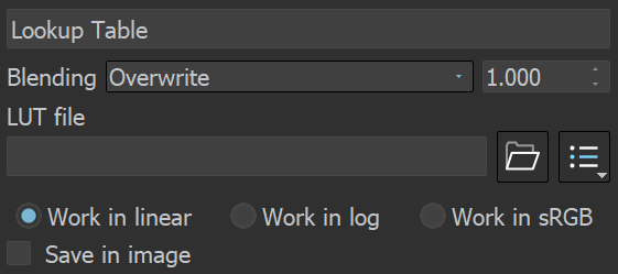
Lookup Table
This correction allows you to remap the image colors based on an IRIDAS .cube LUT (Look-Up Table) file.
Work in linear – The image is considered in linear color space.
Work in log – The image is converted to a logarithmic color space before applying the look-up table. Then it is converted back to linear color space.
Work in sRGB – The image is converted to a sRGB space before applying the look-up table. Then it is converted back to linear color space.
Save in Image – Saves/bakes the LUT effect along with the image. This does not affect multi-channel images (such as multi-channel .exr).
Filmic Tonemap
This correction allows you to control different types of mapping curves, make gamma correction and select a color space. Note that color values are mapped per channel.
Tone mapping space – Specifies the color space where the operator is applied. Converts the image to the selected space and back, if needed. Choose between Linear sRGB and ACEScg.
Type – Specifies the type of curves used for the tone mapping. Choose between Linear, Hejl-Dawson, AMPAS (ACEScg), Hable, and Power Curve.
Log space – Converts the image to log space before applying the tone mapping.
Gamma – Specifies the gamma correction. It is applied before the operator.
Use blue fix – Applies an additional transformation to ACEScg primitives that results in pure blues burning out through cyan instead of magenta. Available when Tone mapping space is set to ACEScg.
AMPAS (ACEScg)
AMPAS mode applies an approximate ACES standard curve.
Hejl-Dawson Type
Shadows – Shadow compression. Higher values darken the shadows, while also brightening the mid tones.
Highlights – Highlight compression. Higher values reduce burnout.
Hable Type
Shoulder strength – Determines how sharp the shoulder is. Higher values sharpen the shoulder, which results in an overall brighter image.
Linear strength – Determines the strength of the effect from changing Linear angle.
Linear angle – Determines the angle of the curve at the base. Higher values increase the angle.
Toe strength – Low to mid tone compression. Higher values darken the low and mid tones.
White point – The intensity, which gets mapped to 1. This parameter scales the whole curve evenly.
Power Curve Type
Toe length – Determines the range of low to mid tones that are compressed.
Toe strength – Low to mid tone compression. Higher values darken the low and mid tones.
Contrast – Higher values increase the contrast between low and high tones.
Shoulder length – Determines the range of mid to high tones that are compressed.
Shoulder strength – Mid to high tone compression. Higher values darken the mid and high tones.
White point – The intensity, which gets mapped to 1. This parameter scales the whole curve evenly.

Proportion Guide
The Proportion Guide layer allows for a number of composition guides to be overlaid on the image.
The available guides presets are Rule of Thirds, Diagonals, Golden Ratio, and Center Cross, whereas Custom Grid allows specifying up to 10 custom columns and rows of the grid.
For all the guides there is a Line Width option, which can be controlled via a slider or spinners, as well as a Color Swatch to control the color of the lines.
For the Custom Grid Rows guides, there are Rows and Columns options to control the rows/columns of the grid.

Examples
Example: Filmic Tonemap Layer Added


Move the slider to see the example renders.
Example: Filmic Tonemap Types

Linear

Hejl_Dawson

AMPAS

Hable

Power Curve
Move the slider to see the example renders.
Example: Light Mix


Move the slider to see the example renders.
Notes
- Color corrections in RGB mode are applied to all Beauty render elements and some Utility render elements too. They are not applied to render elements that present masks or hold geometry or computational data for the rendered frame.