This page provides information about the Displacement in V-Ray for Rhino.
Overview
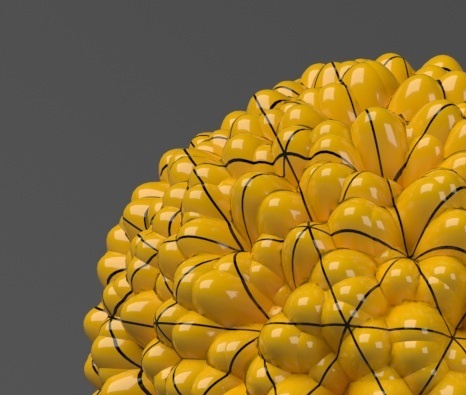
Displacement mapping is a technique for adding detail to your scene geometry without having to model it first. The concept is very similar to bump mapping. However, bump mapping is a shading effect that only changes the appearance of a surface, while displacement mapping actually modifies the surface.
UI Paths
||V-Ray Asset Editor|| > Geometry (right-click) > Displacement
||V-Ray Asset Editor|| > Create Asset (left-click) > Geometries > Displacement

||V-Ray Objects Toolbar|| > Displacement (left-click) > Add Displacement properties to the selection
||V-Ray Objects Toolbar|| > Displacement (right-click) > Remove the Displacement properties from the selection

Rhino Menus Ribbon
||V-Ray|| > Objects > Add Displacement to Selection
Workflow
Create and apply Displacement to the selection . You can use any of the ways shown in the UI path section.
Here Displacement is created from the Asset Editor and applied to the selection.
Then, select the Bitmap as a Map and load a proper file (e.g., .exr). Make sure to select the proper Mode for the loaded map.
The result is seen upon rendering.
To remove the Displacement from a selected object, use the Remove from Selection context option.
Parameters
Enabled – Turns on/off displacement.
Mode/Map – Specifies the mode in which the displacement is rendered:
Normal Displacement – Takes the original surface geometry and subdivides its triangles into smaller sub-triangles which are then displaced.
2D Displacement – Bases the displacement on a texture map that is known in advance. The displaced surface is rendered as a warped height-field based on that texture map. The actual raytracing of the displaced surface is done in texture space, and the result is mapped back into 3D space. The advantage of this method is that it preserves all the details in the displacement map. However, it requires that the object has valid UV coordinates. You cannot use this method for 3D procedural textures or other textures that use object or world coordinates.
Amount – Specifies the amount of displacement. A value of 0.0 means the object appears unchanged. Higher values produce a greater displacement effect. This value can also be negative, in which case the displacement pushes geometry inside the object.
Shift – Specifies a constant which will be added to the displacement map values, effectively shifting the displaced surface up and down along the normals. This value can be either positive or negative. See the Shift example below.
Keep Continuity – When enabled, V-Ray tries to produce a connected surface. Use it when you get splits (usually around sharp edges) in the displaced geometry. See the Keep Continuity example below.
View Dependent – When enabled, the Edge Length parameter determines the maximum length of a sub-triangle edge, in pixels. A value of 1.0, for example, means that the longest edge of the resulting mesh will be about 1 pixel long (when projected on the screen). When disabled, the Edge Length value is the maximum sub-triangle edge length in world units.
Edge Length – Determines the quality of the displacement. The behavior of this parameter depends on the View Dependent parameter above. Note that each triangle of the original mesh is divided into sub-triangles. More sub-triangles mean more detail in the displacement, slower rendering times and more RAM usage. Less sub-triangles mean less detail, faster rendering and less RAM. See the Edge Length example below.
Max Subdivs – Controls the maximum number of sub-triangles generated for every triangle of the original mesh. The maximum number of sub-triangles can be calculated by squaring this value. For example, a value of 256 means that at most 256 x 256 = 65536 sub-triangles will be generated for any given original triangle. It is not a good idea to increase this value much higher than 256. If that's required, it will be better to tessellate the original mesh.
Resolution – Determines the resolution of the displacement texture used by V-Ray. If the texture map is a bitmap, it would be best to match this resolution to the size of the bitmap. For procedural 2d maps, the resolution is determined by the desired quality and detail in the displacement. Note that V-Ray will also automatically generate a normal map based on the displacement map, to compensate for details not captured by the actual displaced surface.
Water Level – Turns on/off water level.
Level Height – Specifies a value below which the geometry will be clipped. See the Height Level example below.

Displacement in Rhino Properties Panel
The  button creates new Displacement.
The 
Make Unique – Makes the selected instance of a Displacement unique. It creates a new Displacement item in the Asset Editor that is linked only to the selected object.
Select Instances – Selects all objects that have an instance of the same Displacement in the viewport.

Example: Shift
Note that the Shift parameter is an absolute value in world units. If you change the Amount, you will probably need to adjust the Shift too.

Shift = -10.0

Shift = -5.0

Shift = 0.0

Shift = 5.0

Shift = 10.0
Example: Height Level
The Height Level parameter is absolute in world units. For this example, Amount is set to 5.0 and Shift is set to 0.0. Note that when Height Level reaches Amount + Shift, all geometry is clipped.

Height Level = 0.0 (no clipping)

Height Level = 1.25

Height Level = 2.5

Height Level = 3.75

Example: Edge Length
This example shows the effects of increasing the Edge Length parameter. In this example View Dependent is enabled, so Edge Length is expressed in pixels. In the examples, the closeup view is a blow-up rather than a zoomed view. This means that Edge Length in the closeup view refers to pixels in the original image, not the blow-up rendering. Click the images for a larger view.
The image below was rendered with a V-Ray Edges map in the Diffuse slot of the material to show the original triangles of the mesh.


Edge Length = 0.5


Edge Length = 1.0

Edge Length = 2.0


Edge Length = 5.0


Edge Length = 10.0
Example: Keep Continuity
The Keep Continuity option is useful for objects with disjoint normals on neighboring triangles, usually because of different smoothing groups. In the middle image below you can see the edge splits produced by disjoint normals. Using the Keep Continuity option avoids this problem. This option will also help to produce a smoother result across material ID boundaries for objects that have been assigned Multi-Sub-Object materials.

No displacement

Keep Continuity = disabled
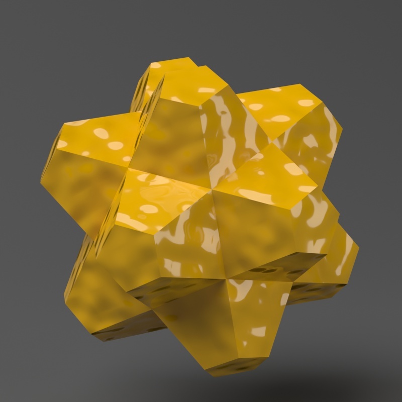
Keep Continuity = enabled
Notes
- The 2D mapping (landscape) method only supports one UV mapping channel.
- Starting with V-Ray 5.20.01, V-Ray special objects (Fur/Clipper/Displacement/Mesh Light/Scatter) are not deleted from the Asset Editor, when the last item with the corresponding special object assigned to it, is deleted from the viewport.