Versions Compared

Key

  • This line was added.
  • This line was removed.
  • Formatting was changed.

This page provides information on the advanced options of the Surface Scattering in Maya. 


Progress Bar Container
step4

Progress Bar - Hyperlink Step
titleOverview
urlChaos Scatter
 
Progress Bar - Hyperlink Step
titleCurve Scattering
urlCurve Scattering
 
Progress Bar - Hyperlink Step
titleSurface Scattering
urlSurface Scattering
 
Progress Bar - Hyperlink Step
titleAdvanced Surface Scattering
urlAdvanced Surface Scattering
 
Progress Bar - Hyperlink Step
titleBounding Box Scattering
urlBounding Box Scattering
 
Progress Bar - Hyperlink Step
titleAdvanced Scatter Features
urlAdvanced Scatter Features


Edge Trimming


Section
Column
width55%

Enable Edge Trimming – Toggles the Edge Trimming function, which "trims the edges" of the Scater geometry, removing any instances that scatter outside of the Target Objects or the Include/Exclude Objects.

The typical use cases of Edge Trimming include:

Fancy Bullets
typecircle
  • Grass lawns - in case of using large grass clumps, no individual grass blades will be growing outside of the defined area.
  • Carpets - in case of using large clumps of strands, no individual strands will be placed outside of the carpet area.
  • Pebbles, rocks, bark chippings, or any other objects which you need to distribute within some specific boundary and make sure no instances stick outside of that boundary (determined based on the mesh element pivot precision).

In addition to making the scattering look more refined and natural, the edge trimming feature boosts performance by removing some of the instances you save from RAM and making parsing time shorter.

See the example for more.

Column
width5%


Column
width40%

Anchor
proxyscatter
proxyscatter

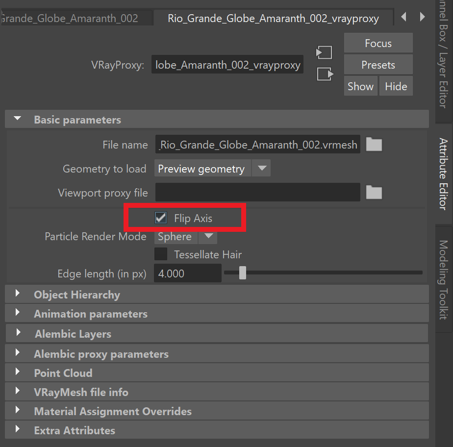
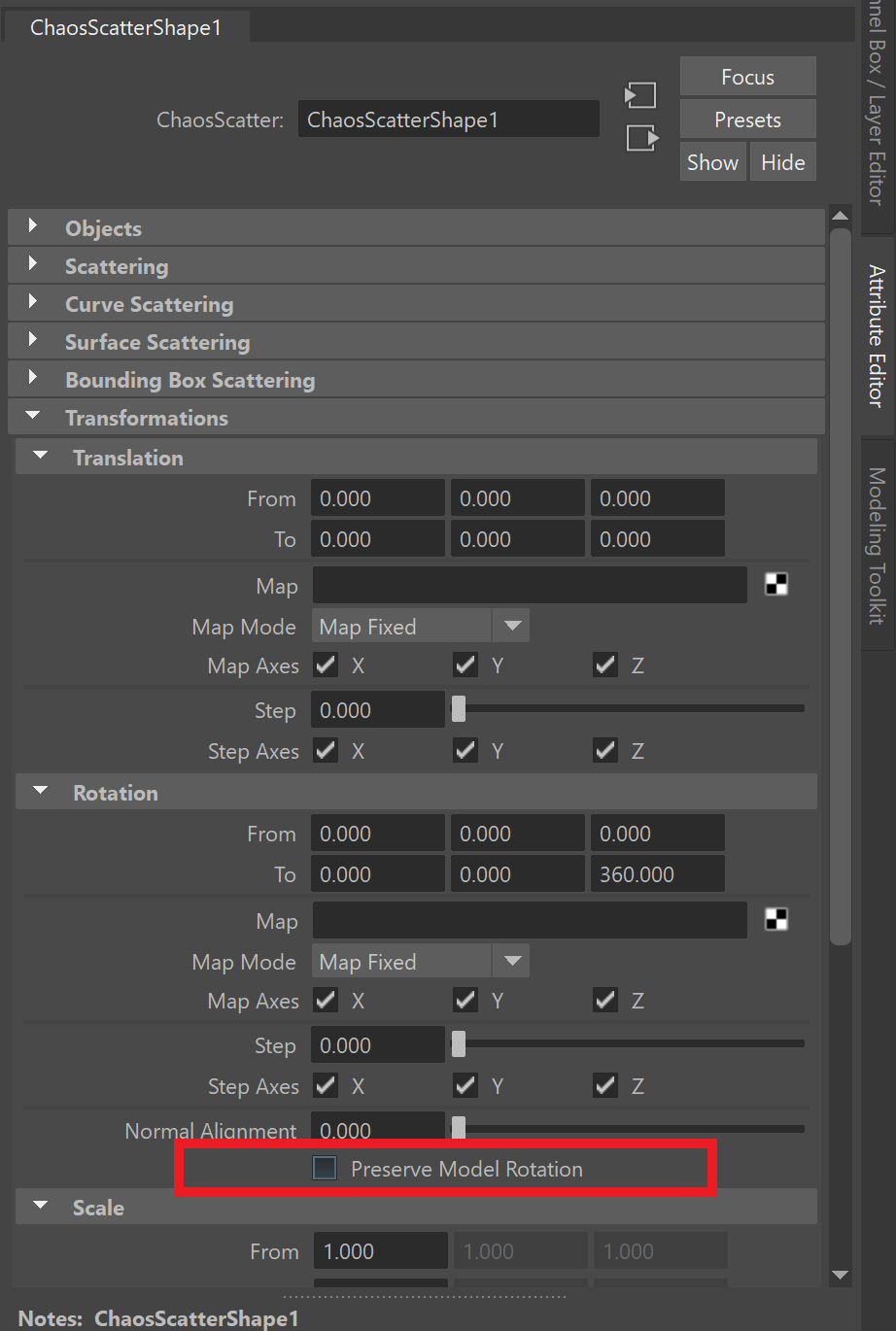
Edge Trimming V-Ray Proxy Files


V-Ray Proxy files are often created in other software, not Maya. This may result in their axes having a different orientation than the native Maya one. Having axes with a different orientation obstructs Chaos Scatter from trimming the instances properly. This is the case for all Chaos Cosmos assets and proxies created in V-Ray for 3ds Max. You need to adjust their axes if you want to scatter such proxy files and use Edge Trimming. To do so:

Fancy Bullets
typecircle
  • Go to the proxy object's attributes, and in the Basic Parameters rollout, enable the Flip Axis option.
  • In the Scatter Object's attributes, go to the Transformations rollout > Rotation and disable the Preserve Model Rotation option.


Section
Column
width5%


Column
width35%

Enable the Proxy's Basic Parameters > Flip Axis

Column
width10%


Column
width35%

Disable the Scatter object's Translations > Rotation > Preserve Model Rotation option

Column
width15%


Anchor
edge
edge

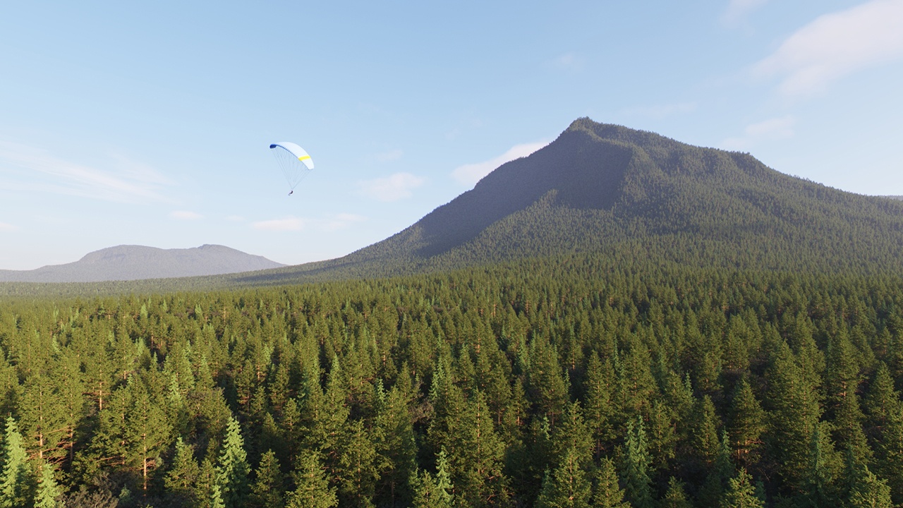
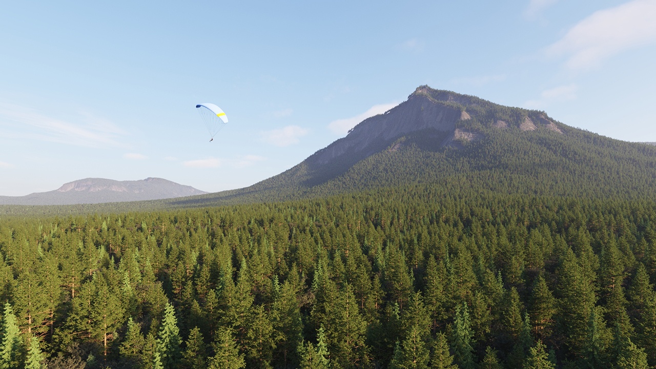
Example: Enable Edge Trimming


Turning on the Edge Trimming function deletes all grass strands that are outside of the Target Object, creating a clean line, imitating that the grass has been professionally cut.


Align
aligncenter

Image_comparison_slider
AddButtonsfalse
LabelBeforeOFF
width60%
LabelAfteron
AttachmentImageBeforelawn-edge-trim-OFF.png
AttachmentImageAfterlawn-edge-trim-ON.png
height60%


Slope Limitation


Section
Column
width55%

Slope Limitation limits scattering only to 'slopes' at certain angles. It can be used to create realistic spread of trees on curved surfaces, for instance. The lower the Angle range is set, the smaller the angle at which scattering stops.

Up Axis – The angles are measured either between the Local Up Axis and the surface normal, or the World Up Axis and the surface normal. You can select which up normal to use:

Local – When enabled, the Slope Limitation is measured according to the up vector of each individual Targets object.
World – When enabled, the Slope Limitation is measured according to the world Y-axis up vector for all Targets objects in the scene.

See the Slope Limitation Up Axis example for more information.

Min Angle/Max Angle – Defines a range of angles to which the scattering is limited. Instances outside of this range get filtered out. See the Min/Max Angle example below for more information.

UI Text Box
typetip

When using the Local Up Axis, freeze the scale of the model.

Column
width5%

Column
width40%


Anchor
axis
axis

Example: Slope Limitation Up Axis


The Local and World Slope Limitations determine the up-vector. The Local option uses the normals of the Target object; the World option uses the Y-axis of the scene. In this example, the Min/Max Angle is set to 0.0°-45.0°.


Align
aligncenter

Image_comparison_slider
AddButtonsfalse
LabelBeforeLocal
width60%
LabelAfterWorld
AttachmentImageBefore02_SlopeLimit_0-45_Rot_Local.jpg
AttachmentImageAfter03_SlopeLimit_0-45_Rot_World.jpg
height60%


Anchor
angle
angle

Example: Min/Max Angle


The Min/Max Angles remove instances based on the angle of the underlying geometry. These options can be used to remove geometry from steep areas as well as shallow areas.

Section
Column
width20%


Column
width60%
Image slider
Panel
borderStylenone

Slope Limitation is disabled

Panel
borderStylenone

Min/Max Angles = 0.0° - 45.0°

Panel
borderStylenone

Min/Max Angle = 0.0° - 20.0°

Panel
borderStylenone

Min/Max Angle = 5.0° - 20.0°

Column
width20%


Altitude Limitations


Section
Column
width55%

Enable Altitude LimitationsToggles the altitude limitations parameters on and off. Altitude defines a height range (in cm) for the scattered geometry to distribute on.

Altitude Limit Mode – Determines the coordinates space used for determining altitude.

Position Independent – The altitude of the surface points on each individual distribute-on object is evaluated relative to the object center while the object rotation and scale still affect the altitude.
World – The altitude of the surface points on each individual distribute-on object is evaluated in world space (after all transforms).

Min Altitude – Determines the minimum altituge range for the scatter objects. Objects below this threshold are not rendered. 

Max Altitude – Determines the maximum altitude range for the scatter objects. Objects above this threshold are not rendered. See the example for more information.

Column
width5%


Column
width40%


Anchor
egAltitude
egAltitude


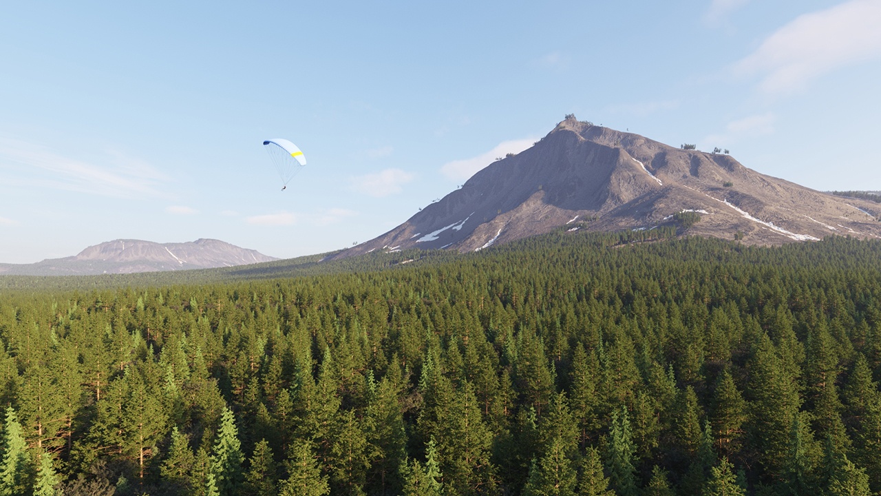
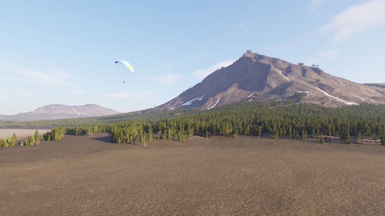
Example: Altitude Limitation

Setting the Max Altitude to 5000.000 cm (500m) limits the scattered trees to that height.


Align
aligncenter

Image_comparison_slider
AddButtonsfalse
LabelBeforeoff
width60%
LabelAftermax altitude 50000
AttachmentImageBefore01_Altitude_Off_1280x720.jpg
AttachmentImageAfter02_Altitude_0-500m_1280x720.jpg
height60%


Progress Bar Container
step4

Progress Bar - Hyperlink Step
titleOverview
urlChaos Scatter
Progress Bar - Hyperlink Step
titleCurve Scattering
urlCurve Scattering
Progress Bar - Hyperlink Step
titleSurface Scattering
urlSurface Scattering
Progress Bar - Hyperlink Step
titleAdvanced Surface Scattering
urlAdvanced Surface Scattering
 
Progress Bar - Hyperlink Step
titleBounding Box Scattering
urlBounding Box Scattering
 
Progress Bar - Hyperlink Step
titleAdvanced Scatter Features
urlAdvanced Scatter Features