![]()
Page History
This page provides information about the Displacement in V-Ray for Rhino.
Overview
...
Displacement mapping is a technique for adding detail to your scene geometry without having to model it first. The concept is very similar to bump mapping. However, bump mapping is a shading effect that only changes the appearance of a surface, while displacement mapping actually modifies the surface.
UI Paths
...
| Section | |||||||||||||||||||||||||||
|---|---|---|---|---|---|---|---|---|---|---|---|---|---|---|---|---|---|---|---|---|---|---|---|---|---|---|---|
|


Workflow
...
| Section | ||||||||||||||||||||||||
|---|---|---|---|---|---|---|---|---|---|---|---|---|---|---|---|---|---|---|---|---|---|---|---|---|
|
...
Parameters
...
| Section | |||||||||||||||||
|---|---|---|---|---|---|---|---|---|---|---|---|---|---|---|---|---|---|
|

...
Displacement in Rhino Properties Panel
...
| Section | |||||||||||||||
|---|---|---|---|---|---|---|---|---|---|---|---|---|---|---|---|
|


| Anchor | ||||
|---|---|---|---|---|
|
...
Example: Shift
...
Note that the Shift parameter is an absolute value in world units. If you change the Amount, you will probably need to adjust the Shift too.
| Section | ||||||||||||||||||||||||||||||||||||||||||||||||||
|---|---|---|---|---|---|---|---|---|---|---|---|---|---|---|---|---|---|---|---|---|---|---|---|---|---|---|---|---|---|---|---|---|---|---|---|---|---|---|---|---|---|---|---|---|---|---|---|---|---|---|
|


| Anchor | ||||
|---|---|---|---|---|
|
...
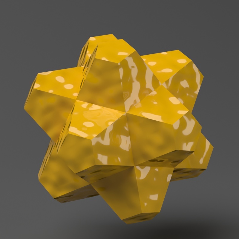
Example: Height Level
...
The Height Level parameter is absolute in world units. For this example, Amount is set to 5.0 and Shift is set to 0.0. Note that when Height Level reaches Amount + Shift, all geometry is clipped.
| Section | |||||||||||||||||||||||||||||||||||||||||||||||||||
|---|---|---|---|---|---|---|---|---|---|---|---|---|---|---|---|---|---|---|---|---|---|---|---|---|---|---|---|---|---|---|---|---|---|---|---|---|---|---|---|---|---|---|---|---|---|---|---|---|---|---|---|
|


...
| Anchor | ||||
|---|---|---|---|---|
|
...
The image below was rendered with a V-Ray Edges map in the Diffuse slot of the material to show the original triangles of the mesh.
| Section | |||||||||||||||||||||||||||||||||||||||||||||||||
|---|---|---|---|---|---|---|---|---|---|---|---|---|---|---|---|---|---|---|---|---|---|---|---|---|---|---|---|---|---|---|---|---|---|---|---|---|---|---|---|---|---|---|---|---|---|---|---|---|---|
|


| Anchor | ||||
|---|---|---|---|---|
|
...
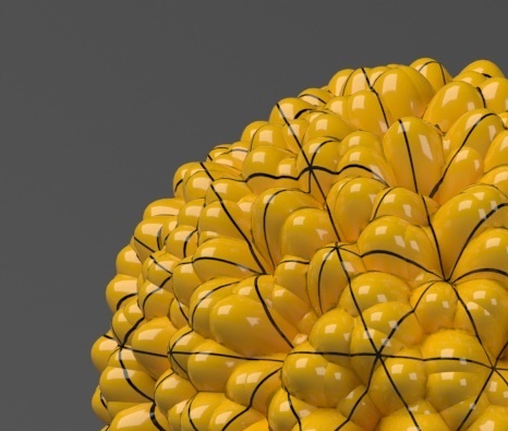
Example: Keep Continuity
...
The Keep Continuity option is useful for objects with disjoint normals on neighboring triangles, usually because of different smoothing groups. In the middle image below you can see the edge splits produced by disjoint normals. Using the Keep Continuity option avoids this problem. This option will also help to produce a smoother result across material ID boundaries for objects that have been assigned Multi-Sub-Object materials.
| Section | |||||||||||||||||||||||||||||||||||||
|---|---|---|---|---|---|---|---|---|---|---|---|---|---|---|---|---|---|---|---|---|---|---|---|---|---|---|---|---|---|---|---|---|---|---|---|---|---|
|


...
Notes
...
| Fancy Bullets | ||
|---|---|---|
| ||
|
...