Versions Compared

Key

  • This line was added.
  • This line was removed.
  • Formatting was changed.

...

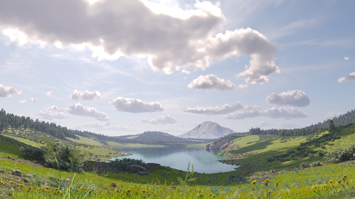
The V-Ray Sun and V-Ray Sky are special features which are provided by the V-Ray renderer. Developed to work together, the V-Ray Sun and V-Ray Sky reproduce the real-life sun and sky environment of the Earth. Both are coded so that they change their appearance depending on the direction of the V-Ray Sun.


How to Set Up

...

Section
Column
width50%

Certain parameters are only available as node inputs for the Sun Light. For optimal editing, open the light in the V-Ray Node Editor. Follow these steps to see all the parameter locations for this node:

Fancy Bullets
typecircle
  • Select the light and switch to the Shader Node Tree in the V-Ray Node Editor
  • Click on the Use V-Ray Light Nodes button that appears in the Node Editor toolbar
  • This creates the Sun Light node in the V-Ray Node Editor. To adjust your view, use the middle mouse button to zoom in and pan.
  • You can now find all parameters associated with the Sub Light node. Some are located on the node itself as input sockets. The rest can be found both in the Node menu in the V-Ray Node Editor right-hand panel and the Data tab.


UI Text Box
typenote

The render engine needs to be set to V-Ray for the V-Ray options to appear in the user interface.

Column
width5%


Column
width45%

Image Added

Click on the GIF to view it in full-size


Node Input Sockets

...

Section
Column
width50%

This section describes the input sockets of the node. Some sockets have dedicated parameters, which are further described below, and some sockets are just inputs.


Transform – Allows a V-Ray Matrix node to be connected to determine the Sun Light's rotation and scale.

Ground albedo color (input socket) – Allows a color node to determine the Ground Albedo.

Shadow color (input socket) – Allows a color node to determine the Shadow Color.

Column
width5%


Column
width45%

Image Added


General

...

Section
Column
width57%50%

Enabled – Turns the sun light on and off.

Intensity – Specifies the brightness of the sun. Since the sun is very bright by default, you can use this parameter to reduce its effect. This option is not available with V-Ray GPU.

Size – Controls the visible size of the sun. This affects the appearance of the sun disc as seen by the camera and reflections, as well as the blurriness of the sun shadows.Filter Color – Shifts the hue of the V-Ray Sun and Sky system towards the specified color. This option is not available with V-Ray GPU.as the blurriness of the sun shadows.

Color Mode – This mode affects the way the Filter Color V-Ray hues the sun and sky light.

Filter – Shifts the V-Ray Sun and Sky hue towards the color specified by either the Filter Color or the Temperature, depending on the Color Temp Mode.
Direct Takes Determines the V-Ray Sun light color either through the Filter Color for the V-Ray Sun lightor the Temperature, depending on the Color Temp Mode. In this case, the light intensity is controlled by the Intensity multiplier and it does not depend on the Sun's position the Sun's position in the sky.
Override – Determines the color of the Sun light through either the Filter Color or the Temperature, depending on the Color Temp Mode. However the intensity is controlled by the position of the V-Ray Sun in the sky. Override – Takes the Filter Color for

Color Temp ModeDetermines how the color of the light is controlled, either Color or Temperature.

Filter Color – When the Color Temp Mode is set to Color, shifts the hue of the V-Ray Sun

light, however the intensity is controlled by the position of the V-Ray Sun in the sky. 

and Sky system towards the specified color. This option is not available with V-Ray GPU.

TemperatureWhen the Color Temp Mode is set to Temperature, this parameter controls the color of the light by degrees Kelvin.

Filter Color – 

Temperature – 

Sky Model – Determines the procedural model used to generate the V-Ray Sky texture:

Preetham et al. – The VRaySky procedural texture is generated based on the Preetham et al. method.
CIE Clear – The VRaySky procedural texture is generated based on the CIE method for a clear sky.
CIE Overcast – The VRaySky procedural texture is generated based on the CIE method for a cloudy sky.
Hosek et al. – The VRaySky procedural texture is generated based on the Hosek et al. method. 
PRG Clear Sky – The VRaySky procedural texture is generated based on the Improved method which has enhanced sunrise and sunset sky.

Ground Albedo – Sets the color of the V-Ray Sun and Sky system's grounds ground. A node can be connected to the input socket of this parameter. This option is not available with V-Ray GPU.

Horiz Illum – Specifies the intensity (in lx) of the illumination on horizontal surfaces coming from the sky. This parameter is enabled when one of the CIE Sky Models are is selected. This option is not available with V-Ray GPU.

Blend Angle – Specifies the angle in degrees where blending occurs between the horizon line and sky. Values close to 0.0 produce a sharper horizon line, while larger values produce a softer horizon line. This option is not available with V-Ray GPU.

Horizon Offset – Allows the user to manually lower the horizon line.

Turbidity – Determines the amount of dust in the air, which in turn affects the color of the sun and sky. Smaller values produce a clear, blue sky and sun similar to what is seen in rural areas, while larger values make the sun and sky more yellow and orange as seen in a big city. This option is not available with V-Ray GPU.

Ozone – Affects the color of the sun light. Available in the range between 0.0 and 1.0. Smaller values make the sunlight more yellow, while larger values make it bluer. This option is not available with V-Ray GPU.

Column
width5%


Column
width38%45%

Image RemovedImage Added

Clouds

...

Section
Column
width57%50%

Clouds On – Enables the cloud system.

Ground Shadows – When enabled, casts shadows from the clouds. See the Clouds Ground Shadows example for more information.

Density – Controls the density of the cumulus and stratus types of clouds. A value of 1 fills up the sky with clouds. See the Clouds Density example for more information.

Denisty Multiplier – 

See the Clouds Density example for more information.

Density Multiplier – A multiplier to the Density parameter. The larger the value, the darker the sky becomes at the horizon. Setting a value of 0 results in no clouds, regardless of the Density value.

Variety – Controls the variety of the cumulus and stratus types of clouds. See the Clouds Variety example for more information.

Seed – Generates a random value, based on the given number, to change the pattern of the clouds and the Contrails.

Cirrus Amount – The maximum value of 1 fills the sky with cirrus clouds. Decreasing the value, lowers the presence of such clouds. When set to 0, the cirrus clouds are completely gone. See the Clouds Cirrus Amount example for more information.

Height (m) – Determines the Clouds position in height. See the Clouds Height example for more information.

Thickness (m) – Lower values make the cumulus and stratus types of clouds thin and sheer/lucent, while higher values make them full and heavy. See the Clouds Thickness example for more information.

Longitude Offset (m) – Moves the cloud system by the X axis. See the Clouds Offset example for more information.

Latitude Offset (m) – Moves the cloud system by the Y axis. See the Clouds Offset example for more information.

Longitude Phase (%) – Controls the phase by the X axis, can be used to fine-tweak the cumulus and stratus clouds appearance. The appearance of the clouds loops at 0, 100, 200, etc. This parameter can be animated to resemble natural clouds appearance.

Latitude Phase (%) – Controls the phase by the Y axis. Can be used to fine-tweak the cumulus and stratus clouds appearance. The appearance of the clouds loops at 0, 100, 200, etc. This parameter can be animated to resemble natural clouds appearance.

Enable Contrails – When enabled, plane contrails are simulates in the sky.

Number of Contrails – Determines the number of contrails generated. See the Number of Contrails example for more information.

Contrails Strength – Determines the opacity of the contrails. Lower values create less opaque trails, which look older. See the Contrails Strength example for more information.

Contrails Distortion – Determines the amount of distortion in the contrails. See the Contrails Distortion example for more details.

Contrails Offset Longitude/Latitude (m) – Offsets the contrails by a given value, according to the X or Y axis. See the Contrails Offset example for more information.

Contrails Time – Determines how long along their way the planes are. See the Contrails Time animation for more details.

Column
width5%


Column
width38%45%

Image RemovedImage Added


...


Anchor
DensityVariety
DensityVariety

Section
Column
width50%

Example:

Clouds

Density


The Clouds Density Density parameter controls the amount number of clouds in the sky. The higher the value, the more clouds appear in the render. 

Image slider
startIndex1
width60%
Panel
borderStylenone

Density_0.jpg

Clouds Density = 0

Panel
borderStylenone

Density_04.jpg

Clouds Density = 0.4

Panel
borderStylenone

Density_08.jpg

Clouds Density = 0.8

Move the slider to see the example renders.

Column
width50%

Example:

Clouds

Variety


This example shows the effect of the Clouds Variety parameter on the clouds' distribution and look.

Image slider
startIndex1
width60%
Panel
borderStylenone

Variety_0.jpg

Clouds Variety = 0

Panel
borderStylenone

Variety_05.jpg

Clouds Variety = 0.5

Panel
borderStylenone

Variety_1.jpg

Clouds Variety = 1

Move the slider to see the example renders.


...

Anchor
Shadows
Shadows

Example:

...

Ground Shadows


The Clouds Ground Shadows option controls whether or not the clouds cast shadows in the scene.

...

Ground_Shadows_On.jpgImage Removed

Section
Column
width25%

beforeLabel

Column
width50%

Image_comparison_slider
LabelBefore

Before after
afterLabelon
off

panel

LabelAfter

borderStylenone

Ground_Shadows_Off.jpgImage Removed

Panel
borderStylenone
on
AttachmentImageBeforeGround_Shadows_Off.jpg
AttachmentImageAfterGround_Shadows_On.jpg

Column
width50%


...

Anchor
CirrusHeight
CirrusHeight

Section
Column
width50%

Example:

Clouds

Cirrus Amount


This example shows how increasing the Clouds Cirrus Amount increases the appearance of the cirrus clouds in the render.

Image slider
Panel
borderStylenone

Cirrus_Amount_0.jpg

Clouds Cirrus Amount = 0

Panel
borderStylenone

Cirrus_Amount_05.jpg

Clouds Cirrus amount = 0.5

Panel
borderStylenone

Cirrus_Amount_1.jpg

Clouds Cirrus amount = 1

Move the slider to see the example renders.

Column
width50%

Example:

Clouds

Height (m)


This example shows how the clouds change their position in the sky with by increasing the Clouds Height (m) value. 

Image slider
Panel
borderStylenone

Height_500.jpg

Clouds Height (m) = 500

Panel
borderStylenone

Height_1000.jpg

Clouds Height (m) = 1000

Panel
borderStylenone

Height_1500.jpg

Clouds Height (m) = 1500

Move the slider to see the example renders.

...

Anchor
ThicknessOffset
ThicknessOffset

Section
Column
width50%

Example:

Clouds

Thickness (m)


The Clouds Thickness (m) parameter specifies how full the clouds are. Lower values make them thinner and sheerer, while higher values make them look heavy. 

Image slider
Panel
borderStylenone

Thickness_200.jpg

Clouds Thickness Thickness (m) = 200

Panel
borderStylenone

Thickness_500.jpg

Clouds Thickness (m) = 500

Panel
borderStylenone

Thickness_800.jpg

Clouds Thickness (m) = 800

Move the slider to see the example renders.

Column
width50%

Example:

Clouds

Offset


The following example demonstrates how changing the Clouds Longitude Offset (m) and the Clouds Latitude Offset (m) parameters affects the appearance of the clouds.

Image slider
Panel
borderStylenone

Offset_X0_Y0.jpg

No offset

Panel
borderStylenone

Offset_Xminus250_Y0.jpg

Clouds Longitude Offset (m) = -250, Clouds Latitude Offset (m) = 0

Panel
borderStylenone

Offset_Xminus250_Y500.jpg

Clouds Longitude Offset (m) = -250, Clouds Latitude Offset (m) = 500

Move the slider to see the example renders.

...

Section
Column
width45%

Example: Number of Contrails


Note that the contrails are spread randomly across the sky. In most cases, the camera does not capture all of the contrails.

Image slider
minLabel5
startIndex1
maxLabel40
Panel
borderStylenone

02_Number of contrails_5.jpg

Number of Contrails = 5

Panel
borderStylenone

03_Number of contrails_20.jpg

Number of Contrails = 20

Panel
borderStylenone

04_Number of contrails_40.jpg

Number of Contrails = 40

Move the slider to see the example renders.

Column
width10%


Column
width45%

Example: Contrails Strength


This example shows how the Contrails Strength parameter makes the contrails more visible and prominent in the sky.

Image slider
minLabel0.1
startIndex1
maxLabel1.0
Panel
borderStylenone

01_Contrails strenght_01.jpg

Contrails Strength = 0.1

Panel
borderStylenone

03_Contrails strenght_05.jpg

Contrails Strength = 0.5

Panel
borderStylenone

04_Contrails strenght_1.jpg

Contrails strength = 1.0

Move the slider to see the example renders.

...

Section
Column
width45%

Example: Contrails Distortion


The Contrails Distortion parameter is used to achieve some variety in the trace line. Move the slider to see the example renders.

Image slider
minLabel0.1
startIndex1
maxLabel1.0
Panel
borderStylenone

01_Contrails distortion_01.jpg

Contrails Distortion = 0.1

Panel
borderStylenone

03_Contrails distortion_05.jpg

Contrails Distortion = 0.5

Panel
borderStylenone

04_Contrails distortion_1.jpg

Contrails Distortion = 1.0

Column
width10%


Column
width45%

Example: Contrails Offset


The Contrails Offset Longitude (m) and the Contrails Offset option introduces Latitude (m) options introduce an offset along the X or Y direction in the sky. Move the slider to see the example renders.

Image slider
startIndex1
Panel
borderStylenone

01_Contrails offset_X0_Y0.jpg

Contrails Offset Longitude (m) = 0, Contrails Offset Latitude (m) = 0

Panel
borderStylenone

02_Contrails offset_X5000_Y0.jpg

Contrails Offset Longitude (m) = 5000,Contrails Offset Latitude (m) = 0

Panel
borderStylenone

03_Contrails offset_X0_Y5000.jpg

Contrails Offset Longitude (m) = 0, Contrails Latitude Offset (m) = 5000


...

Anchor
contTime
contTime

...

Options

...

Section
Column
width57%50%

Invisible – When enabled, makes the sun invisible, both to the camera and to reflections. This is useful to prevent bright speckles on glossy surfaces where a ray with low probability hits the extremely bright sun disk.

Affect Diffuse – Determines whether the Sun affects the diffuse properties of the materials.

Affect Specular – Determines whether the Sun affects the specular of the materials. The multiplier controls the sun's contribution to specular reflections.

Affect Atmospherics – When enabled, the light influences the atmospheric effects in the scene. This option is not available with V-Ray GPU.

Diffuse Contribution – Controls the Sun's contribution to the diffuse illumination.

Specular Contribution – Controls the Sun's contribution to the specular reflection.

Atmospherics Contribution – Determines the amount of influence the light has on the atmospheric effects.

LPE Label – Allows a label to be assigned, which can be used to reference the light in a Light Path Expression. This is especially useful when working with the Light Select render element to evaluate custom light contribution in the scene.

Column
width5%


Column
width38%45%

Image RemovedImage Added


Shadows

...

Section
Column
width57%50%

Shadows – When enabled, the objects in the scene cast shadows.

Shadow Color/Texture– Specifies a color or a texture map for the shadows. A node can also be connected to this parameter socket. This option is not available with V-Ray GPU.

Shadow Bias – Moves the shadow toward or away from the shadow-casting object. Higher values move the shadow toward the object, while lower values move it away. If this value is too extreme, shadows can "leak" through places they shouldn't or "detach" from an object. Other effects from extreme values include moire patterns, out-of-place dark areas on surfaces, and shadows not appearing at all in the rendering.

Atmos Shadows – When enabled, the atmospheric effects in the scene cast shadows. This option is not available with V-Ray GPU.

Column
width5%

Column
width38%45%

Image RemovedImage Added


Photon Emission

...

Section
Column
width57%50%

Photon Radius – Determines the radius of the area in which photons are shot. This area is represented by the cylinder around the Sun's ray vector. This parameter has an effect when photons are used in caustics.

Caustic Subdivs – Used by V-Ray when calculating Caustics. Lower values mean more noisy results but render faster. Higher values produce smoother results but take more time. This option is not available with V-Ray GPU.

Caustic MultMultiplier – Used by V-Ray when calculating Caustics. This multiplier controls the brightness of the caustics. This option is not available with V-Ray GPU.

Column
width5%


Column
width38%45%

Image RemovedImage Added