![]()
Page History
...
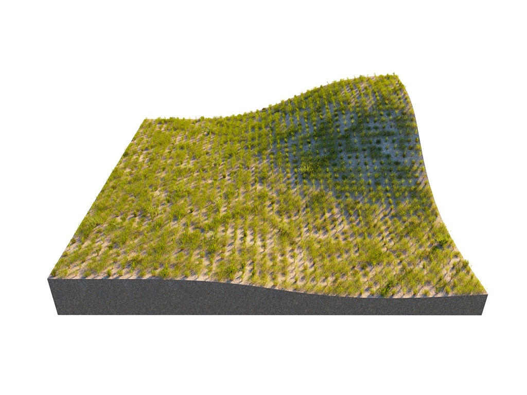
This example shows the difference between Random distribution and UV map modes.
...
| width | 25% |
|---|
| Column | |||||||||||||||||||
|---|---|---|---|---|---|---|---|---|---|---|---|---|---|---|---|---|---|---|---|
| |||||||||||||||||||
|
| Before after | ||||||||||
|---|---|---|---|---|---|---|---|---|---|---|
| ||||||||||
|

...
| Anchor | ||||
|---|---|---|---|---|
|
| Anchor | ||||
|---|---|---|---|---|
|
| Section | ||||||
|---|---|---|---|---|---|---|
|
...
| width | 25% |
|---|
...
| Section | |||||||||||||||||||
|---|---|---|---|---|---|---|---|---|---|---|---|---|---|---|---|---|---|---|---|
|
...
The bounding box of the model is represented with a red box. The pivot of the model is represented with a blue sphere.
| Sectionbefore-after | |||||||||||||||||||||||||||||
|---|---|---|---|---|---|---|---|---|---|---|---|---|---|---|---|---|---|---|---|---|---|---|---|---|---|---|---|---|---|
| width
| 25%
| column
| ||||||||||||||||||||||||||
|


When Edge trimming is off, the whole clumps are scattered causing some of the flowers (sub-object elements) to grow outside of the distribute-on object. Each model is scattered as expected (its pivot is placed within the boundaries of the distribute-on object), however the sub-mesh elements (individual flowers) are growing outside of the boundaries, because they are a part of the model.
...
The Local and World Slope Limitations determine the up-vector. The Local option uses the normals of the Distribute-on target object; the World option uses the Z-axis of the scene. In this example, the Slope Limitation Angle [°] is set to 0.0-45.0.
| Sectionbefore-after | |||||||||||||||||
|---|---|---|---|---|---|---|---|---|---|---|---|---|---|---|---|---|---|
| |||||||||||||||||
| |||||||||||||||||
|
| Column | |||||||||||||||||
|---|---|---|---|---|---|---|---|---|---|---|---|---|---|---|---|---|---|
| |||||||||||||||||
|
| Column | |
|---|---|
| width | 25%
Altitude Limitation
...
| Section | |||||||||||||||
|---|---|---|---|---|---|---|---|---|---|---|---|---|---|---|---|
|


...