The Surface Scattering rollout is part of the Chaos Scatter parameters.
Random Distribution
This mode scatters instances randomly on all mesh and closed spline distribution objects. It is enabled by default.
UV channel – Determines the UV channel to guide the mapping coordinates. When a custom map is used, this option is disabled, and the UV channel in the Bitmap settings is used instead.
Pattern – Selects from predefined distribution maps or chooses a custom map.
None – No map is selected.
Custom map – Uses a custom map.
Distorted streaks high/low – Distorted streaks pattern with different densities.
Groups high/low – Groups pattern with different densities.
Fractal patches high/low – Fractal patches pattern with different densities.
Straight lines high/low – Straight lines pattern with different densities.
Stretched patches high/low – Stretched lines pattern with different densities.
Map – Allows a black and white texture map to be assigned. The map determines how the instances are scattered on the surface. See the Map examples below.
Count – Determines the exact number of instances to scatter. If the Per square option is enabled, the scattering is defined by the density. See the Count example below.
Per square – When enabled, the Count amount is multiplied by the specified edge length (value next to Per square). See the Per square example below.

Example: Count
This example shows the exact instances count on a target object.
Example: Per square
The number of instances here is determined by the count combined with the target object's surface size. The value specifies the length of the distribution area's side/edge.

Count = 1000

Count = 2500

Count = 10000

Count = 1000; Per Square = Off

Count = 1000; Per Square = 1000

Count = 1000; Per Square = 4000

Count = 1; Per Square = 100

Count = 1; Per Square = 1000
Example: Map
The Map determines the approximate count of instances based on texture input. Black color in the texture discards all instances in the respective area.

Count = 5000; Checker Map

Count = 5000; Noise Map

Count = 5000; Gradient Map
Position Distribution
This mode specifies the position of the instances based on a pattern.
UV channel – Determines the UV channel.
Pattern – Determines a pattern to use for scattering. See the Pattern example below.
Grid – Rectangular grid.
Running grid – Rectangular grid with every other row offset by half of the grid spacing.
Hex grid – Arranges instances into hexagons.
Override by planar mapping – When enabled, a simple planar UVW mapping is created and used instead of the pre-existing UVW channels.
Lock V – When enabled the values of the V coordinate for Spacing, Jitter and Offset are locked to the U coordinate's values.
Spacing [%] – Scales the pattern in UV space. When Spacing is set to 100%, the pattern occupies the whole space. When Spacing is set to 50%, the pattern is repeated twice. See the Spacing [%] example below.
Jitter [%] – Determines what percentage of the instances are randomly placed. When Jitter is set to 0, all instances are placed according to the UVW mapping. When Jitter is set to 100, all instances are randomly placed. See the Jitter [%] example below.
Offset [%] – Offsets the pattern by the given value (in percentages). Keep in mind that 0% and 100% Offset gives the same result, as 100% moves the pattern by one whole repetition. See the Offset examples below.

Example: Mode
This example shows the difference between Random distribution and UV map modes.

Example: Pattern
This example shows the different pattern types.
Example: Spacing [%]
This example shows how the spacing parameter affects the distances between the instanced model objects.

Spacing [%] = 10; Pattern = Grid

Spacing [%] = 10; Pattern = Running grid

Spacing [%] = 10; Pattern = Hex grid

Pattern = Grid; Spacing [%] = 10

Pattern = Grid; Spacing [%] = 25

Pattern = Grid; Spacing [%] = 50

Pattern = Grid; Spacing [%] = U 10; V 25

Pattern = Grid; Spacing [%] = U 10; V 50
Example: Jitter [%]
This is how Jitter affects the random placement of instanced model objects. When set to 0, all instances are placed according to the UVW mapping. When set to 100, all instances are randomly placed.

Pattern = Grid; Jitter [%] = 0

Pattern = Grid; Jitter [%] = 100

Pattern = Grid; Jitter [%] = 200
Example: Offset by Single Axis - V
For this example, the Pattern is set to a rectangular Grid. The offset is applied to the U axis only (the Lock V option is disabled).
Example: Offset Locked UV
For this example, the Pattern is set to a rectangular Grid. The offset is applied to both the U and V axes (the Lock V option is enabled).

Pattern = Grid; Offset [%] = U 0; V 0

Pattern = Grid; Offset [%] = U 0; V 25

Pattern = Grid; Offset [%] = U 0; V 50

Pattern = Grid; Offset [%] = U 0; V 75

Pattern = Grid; Offset [%] = U 0; V 100

Pattern = Grid; Offset [%] = U 0; V 0

Pattern = Grid; Offset [%] = U 25; V 25

Pattern = Grid; Offset [%] = U 50; V 50

Pattern = Grid; Offset [%] = U 75; V 75

Pattern = Grid; Offset [%] = U 100; V 100
Edge trimming
Trims elements of instances outside of distribute-on objects. It affects both base objects and include/exclude splines. See the Edge trimming example below.
Starting with V-Ray 6, update 1.1, the edge trimming feature is available with Chaos Scatter 2.6.0 and later.
Edge trimming is used to trim scattered instances consisting of multiple mesh elements so that they stay within the boundaries of the distribute-on objects or include/exclude splines. If a pivot of any integral part of the instance (any sub-mesh element of the instanced model) falls outside of the area specified by the scatter, such part is not rendered. This is a simplification, but you can imagine the pivot as a point on the distribute-on object from which an element is growing.
The typical use cases of Edge Trimming include:
- Grass lawns - in case of using large grass clumps, no individual grass blades will be growing outside of the defined area.
- Carpets - in case of using large clumps of strands, no individual strands will be placed outside of the carpet area.
- Pebbles, rocks, bark chippings, or any other objects which you need to distribute within some specific boundary and make sure no instances stick outside of that boundary (determined based on the mesh element pivot precision).
In addition to making the scattering look more refined and natural, the edge trimming feature boosts performance by removing some of the instances you save from RAM and making parsing time shorter.
If Edge trimming doesn't seem to be working correctly (e.g. some elements of the model are expected to be trimmed, but they are still visible), try resetting the model's XForm in 3ds Max by selecting the model and then going to Command Panel > Utilities and click Reset XForm.


Example: Edge trimming
This example shows how some scattered clumps of flowers are trimmed. The clump of flowers is a single mesh consisting of multiple sub-object elements.
The bounding box of the model is represented with a red box. The pivot of the model is represented with a blue sphere.


When Edge trimming is off, the whole clumps are scattered causing some of the flowers (sub-object elements) to grow outside of the distribute-on object. Each model is scattered as expected (its pivot is placed within the boundaries of the distribute-on object), however the sub-mesh elements (individual flowers) are growing outside of the boundaries, because they are a part of the model.
When Edge trimming is on, each model is scattered the same way as with edge trimming off (its pivot is placed within the boundaries of the distribute-on object). However, the sub-mesh elements (individual flowers) are only growing inside this boundary of the distribute-on surface.
Slope Limitation
Limits scattering only to 'slopes' at certain angles. It can be used to create realistic spread of trees on curved surfaces, for instance. The lower the Angle range is set, the smaller the angle at which scattering stops.
Angle [°]– Defines a range of angles to which the scattering is limited. Instances outside of this range get filtered out. The angles are measured either between the Local up vector and the surface normal or the World up vector and the surface normal. You can select which up normal to use in the option below. See the Slope Limitation Angle [°] Example.
Local – When enabled, the Slope Limitation is measured according to the up vector of each individual Distribute-on target object. See the Slope Limitation orientation Example.
World – When enabled, the Slope Limitation is measured according to the world Z-axis up vector for all Distribute-on target objects in the scene. See the Slope Limitation orientation Example.

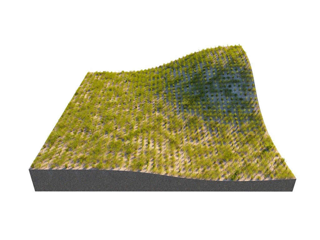
Example: Slope Limitation Angle [°]
The Slope Limitation Angle [°] removes instances based on the angle of the underlying geometry. This option can be used to remove geometry from steep areas as well as shallow areas.

Slope Limitation = disabled

Slope Limitation Angle [°]= 0.0 - 45.0

Slope Limitation Angle [°]= 0.0 - 20.0

Slope Limitation Angle [°]= 5.0 - 20.0
Example: Slope Limitation orientation
The Local and World Slope Limitations determine the up-vector. The Local option uses the normals of the Distribute-on target object; the World option uses the Z-axis of the scene. In this example, the Slope Limitation Angle [°] is set to 0.0-45.0.


Altitude Limitation
Еnables instances limitation in the given altitude range.
Range – Defines the range of altitude units in World or Position Independent mode. See the Altitude Limitation example below.
World – The altitude of the surface points on each individual distribute-on object is evaluated in world space (after all transforms).
Position Independent – The altitude of the surface points on each individual distribute-on object is evaluated relative to the object center while the object rotation and scale still affect the altitude.
Falloff Curve – Opens the Altitude limitation falloff curve editor. This allows specifying the density of the scattered objects depending on their altitude. Lowering the point on the left side of the curve results in lowering the density of the objects closer to the minimum altitude range. Lowering the point on the right side of the curve results in lowering the density of the objects close to the maximum altitude range. See the Altitude Limitation example below.


Example: Altitude Limitation
In this example, the Altitude Limitation and the Altitude Limitation Falloff parameters are showcased. Setting the Altitude Range max to 500 cuts off the scattered forest at that height. Adding Falloff thins out the forest at the lower point of the curve.

Altitude Limitation = Disabled

Altitude Limitation Range = 0 - 500

Altitude Limitation Falloff Curve = ascending

Altitude Limitation Falloff Curve = descending
Instance Editor
Edit Instances – Switches to 'Instances' sub-object mode. This allows individual instances to be manipulated. Only the instances visible in the viewport can be edited. This option is only useful for small numbers of instances, otherwise it might cause a crash. If you select 100 or more instances, Chaos Scatter displays a warning. To switch out of this option, click Edit Instances one more time. The edited instances are ignored by the Avoid collisions option, the Include/Exclude splines option, Slope limitation and by Camera clipping.
Keep in mind that if you edit the original model of the scattered instances, after you've edited them, they are reset back to their original state. To avoid this, edit your instances after finalizing the state of the original model and the Scatter.
Brush – Toggles on and off the paint mode. In this mode, instances are painted by the user in the radius of the painted positions. Right-click on the button to reset the changes
This tool is meant for small adjustments to scenes. Using it on a large scale may slow down scattering performance.
Erase – Toggles on and off the erase mode. In this mode all the instances in the radius of painted positions are erased (by editing). Right-click on the button to reset the changes
This tool is meant for small adjustments to scenes. Using it on a large scale may slow down scattering performance.
Brush Radius – Defines the radius of painted brush.
Painting Rate – A number of instances that should be tried to paint upon a brush actions in the brush area. The value ranges from min 1 to max 200.
Follow Scatter Rules – When this option is not checked, you can brush outside of specified areas or ignore rules like Avoid Collision, Slope Limitation, Altitude Limitation, Edge Trimming, or Camera Clipping.
Erased Only Placed Instances – When enabled, erase the instances that were painted with the brush.
Convert to Max geometry – When enabled, converts the Chaos Scatter instances into 3ds Max instances. This option is only useful for small numbers of instances, otherwise it might cause a crash.

Example: Brush/Erase
This example shows how the Brush and Erase functions work in the 3ds Max viewport.

Example: Brush/Erase
This example shows how increasing the Brush radius and Painting rate affect the scatter instances.
