Versions Compared

Key

  • This line was added.
  • This line was removed.
  • Formatting was changed.

...

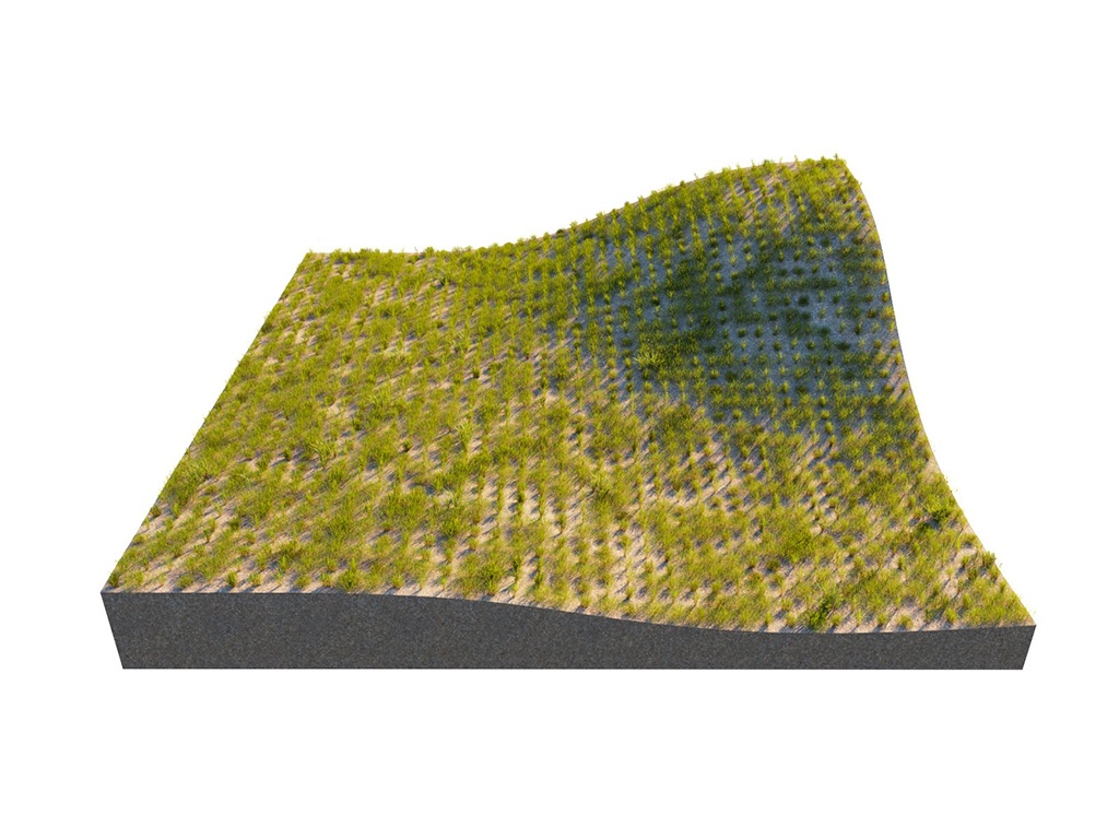
This example shows the difference between Random Distribution and UV Grid modes.


columnwidth25%column
Sectionbefore-after
afterLabel
UV Grid
beforeLabel
Random Distribution
alignalign
width50%
Panel
borderStyle
none
center

Image_comparison_slider
AddButtonsfalse
LabelBeforeRandom Distribution
LabelAfterUV Grid
AttachmentImageBefore01_ModeRandomDistribution_InstancesCount5000.jpg
AttachmentImageAfter02_ModeUVGrid_PatternGrid_Spacing0x025.jpg

Image Added

25%
Panel
borderStylenone

Image Added

Column
width


Random Distribution

...

Section
Column
width60%

Instances Count – Gives the total number of instances on all Host objects. Note that adding Area Modifiers or defining Slope Limitation will decrease this number. If the Per Area option is enabled, the scattering is defined by the density. See the Instances Countexample below.

Per Area – When enabled, the number of instances is determined by the count combined with the size of the host's surface. The value specifies the length of the distribution area's side/edge. If the Count value is set to 1, this number determines the relative density of the instances. See the Per Area example below.

Density – Determines the approximate count of instances based on texture input. Black color in the texture discards all instances in the respective area. Areas colored with white receive the maximum number of instances. See the Density example below.

Map Channel – Determines the UV channel. See the Density Map example below.

Column
width5%

Column
width35%

SketchUp2023_VRay6.2_Scatter_Parameters_Surface

...

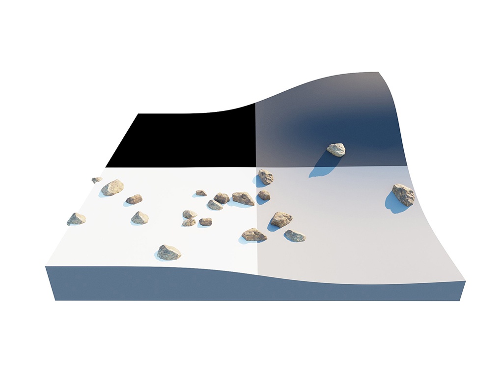
Using a Density map generates brand new instance distribution. The total number of instances (approximate to the 'Instance Count' value) is preserved and distributed on all surfaces that correspond to map values above 0 (parts of the map not being purely black). Instances are more likely to be generated in areas with higher Density map values than darker ones.


columnwidth25%columnwidth50%
Sectionbefore-after
afterLabel
Checker Map
dark
true
beforeLabel
Off
alignalign
Panel
borderStyle
none
center

Image_comparison_slider
AddButtonsfalse
LabelBeforeDensity Map Off
LabelAfterDensity Map Checker
AttachmentImageBefore01_DensityMap-Off_InstancesCount-20.jpg
AttachmentImageAfter02_DensityMap-Checker_InstancesCount-20.jpg

Image Added

25%
Panel
borderStylenone

Image Added

Column
width


UV Grid

...

Section
Column
width60%
UI Text Box
typenote

UVs should be set correctly on every surface, not on the whole object.

Pattern – Determines a pattern to use for grid scattering. See the Pattern example below.

Grid – Rectangular grid.
Running Grid – Rectangular grid with every other row offset by half of the grid spacing.
Hexagonal Grid Arranges the instances into hexagons.

Map Channel – Determines the UV channel.

Spacing – Scales the pattern in UV space. When Spacing is set to 1, the pattern occupies the whole space. When Spacing is set to 0.5, the pattern is repeated twice. See the Spacing example below.

Jitter – Determines what proportion of the instances are randomly placed. When Jitter is set to 0 all instances are placed according to the UV mapping. When Jitter is set to 1 all instances are randomly placed. See the Jitter example below.

Offset – Offsets the pattern by the given value (in percentages). Keep in mind that 0 and 1 Offset give the same result, as 1 moves the pattern by one whole repetition. See the Offset examples below.

Lock– When enabled the values of the V coordinate forSpacing, Jitter and Offset are locked to the U coordinate's values.

Column
width5%

Column
width35%

SketchUp2023_VRay6.2_Scatter_Parameters_Surface_UVGrid

...

This example shows how a group of multiple guest objects can be distributed over several more than one host object. 


columnwidth20%columnwidth60
Sectionbefore-after
afterLabel
0→45
dark
true
beforeLabel
0→180
alignalign
Panel
borderStyle
none
center

Image_comparison_slider
AddButtonsfalse
LabelBefore0-180
LabelAfter45-180
AttachmentImageBefore01_InstancesCount250_MultipleHosts_SlopeLimitation0-180.jpg
AttachmentImageAfter02_InstancesCount250_MultipleHosts_SlopeLimitation45-180.jpg

Column
width20%

Image Added

Panel
borderStylenone

Image Added


Edge Trimming

...

Section
Column
width60%

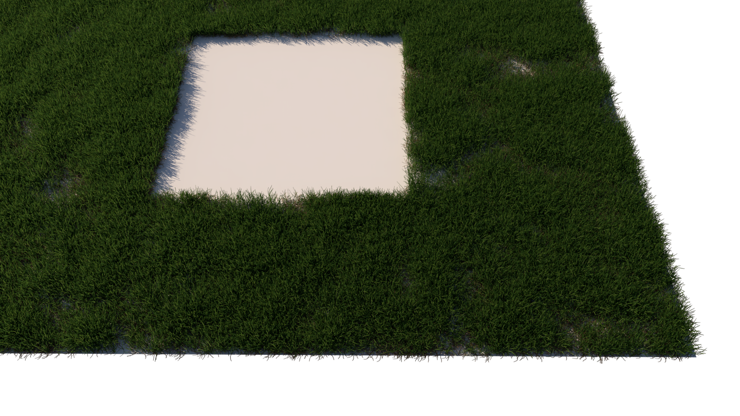
Edge Trimming – Trims elements of instances outside of the host boundaries. It affects both host objects and Area modifiers.

Edge trimming is used to trim scattered instances consisting of multiple mesh elements so that they stay within the boundaries of the host objects, taking into account the modifiers added to the Area Modifiers list. If an origin of any integral part of the instance (any sub-mesh element of the instanced model) falls outside of the area specified by the scatter, such part is not rendered. This is a simplification, but you can imagine the origin as a point on the host object from which an element is growing.

The typical use cases of Edge Trimming include:

  • Grass lawns - in case of using large grass clumps, no individual grass blades will be growing outside of the defined area.
  • Carpets - in case of using large clumps of strands, no individual strands will be placed outside of the carpet area.
  • Pebbles, rocks, bark chippings, or any other objects which you need to distribute within some specific boundary and make sure no instances stick outside of that boundary (determined based on the mesh element origin precision).


In addition to making the scattering look more refined and natural, the edge trimming feature boosts performance by removing some of the instances you save from RAM and making parsing time shorter.

Column
width5%


Column
width35%


...


Example: Edge Trimming


LabelBefore
Alignbefore-after
alignafterLabelcenter
Image_comparison_slider
On
beforeLabelOff
width
Panel
50%
borderStyle
LabelAfter
none
On

Image Added

AttachmentImageBeforeedge_trimming-not_trimmed.png
AttachmentImageAfteredge_trimming-trimmed.png
height
Panel
borderStylenone

Image Added

50%


Notes

...

Section
Fancy Bullets
typecircle
  • Scene units in SketchUp are always calculated in inches.

...