This page provides information about V-Ray Scatter in V-Ray for SketchUp.


Overview


The V-Ray Scatter tool creates instances of objects using the surfaces and edges of other objects or splines to generate points.


UI Paths


||Asset Editor|| > Geometries (right-click) > Scatter

||Asset Editor|| > Create Asset (left-click) > Geometries > Scatter


||V-Ray Objects Toolbar|| > Scatter over Selection

||V-Ray Objects Toolbar|| > Scatter Viewer 

SketchUp2023_VRay6.2_Toolbar_Scatter


SketchUp Menus Ribbon

||Extensions|| > V-Ray > Objects > Scatter over Selection

||Extensions|| > V-Ray > Objects > Scatter Viewer


Accessing Scatter Viewport Preview from the V-Ray Toolbar or the V-Ray Menu in Sketchup 2023 or later versions opens the following notification. 

SketchUp2023_VRay6.2_Toolbar_Scatter_ViewerNotification


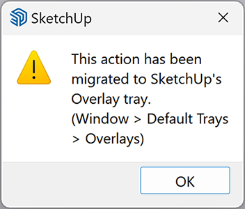
||Window|| > Default Tray > Overlays > Scatter Viewport Preview

SketchUp2023_VRay6.2_Overlays_ScatterViewer.png


Scatter Workflow


V-Ray Scatter consists of two types of objects – Host objects and Guest objects that are scattered over the Host object's surface. There are several ways to create Scatter Host and Guest objects.


Creating Scatter Host Objects

  • Select an object in the viewport. Click the Scatter over Selection button from the V-Ray Geometry Toolbar. The button is inactive until an object is selected in the viewport window.

  • Select an object in the viewport. Go to the Extensions menu > V-Ray > Objects > Scatter over Selection.

  • Select an object in the viewport. Open the Asset Editor > Geometry > Scatter and use the Apply to Selection option.


Creating Scatter Guest Objects

  • Select an object in the viewport and use the Add Guests button in the Asset Editor. The object appears under the Add Guests button.

  • Drag and drop a preselected scene object from the viewport onto the Scatter Host object.
  1. First, make sure the Scatter over Selection is still active after Scatter is applied over the Host object.
  2. Then select the object that will become a Guest.
  3. Drag and drop it onto the Scatter Host object.

A SketchUp component used as a Scatter guest needs to have the component instance present in the scene in order to scatter it. Deleting the instance removes the guest despite the component still being present in the SketchUp project. The extra object can be manually hidden (right-click > hide), placed in a separate hidden layer, or moved on the Scatter host surface after scattering.


SketchUp2023_VRay6.2_Scatter_Create


Scatter Viewport Preview Workflow


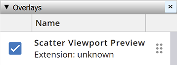
Enable the Scatter Viewport Preview from the Overlays tray in Sketchup 2023 or later versions. This provides a visual representation of the scattered objects in the viewport. 


SketchUp2023_VRay6.2_ScatterViewportPreview


Scatter Viewer In Previous SketchUp Versions


UI Paths


||V-Ray Objects Toolbar|| > Scatter Viewer


SketchUp Menus Ribbon

||Extensions|| > V-Ray > Objects > Scatter Viewer


Workflow


For SketchUp versions earlier than 2023, the Scatter Viewer is accessed through the V-Ray Toolbar and V-Ray Menu.

Introduce a Scatter Guest from the Asset Editor or by dragging and dropping a preselected object from the viewport onto the Scatter Host object. In this case, the Guest object can be removed by using the drag + shift function. Scatter Viewer must be active in order to add a Guest by dragging a preselected object from the viewport onto the Host object.


Example of introducing Guest objects to the Host object


Scatter


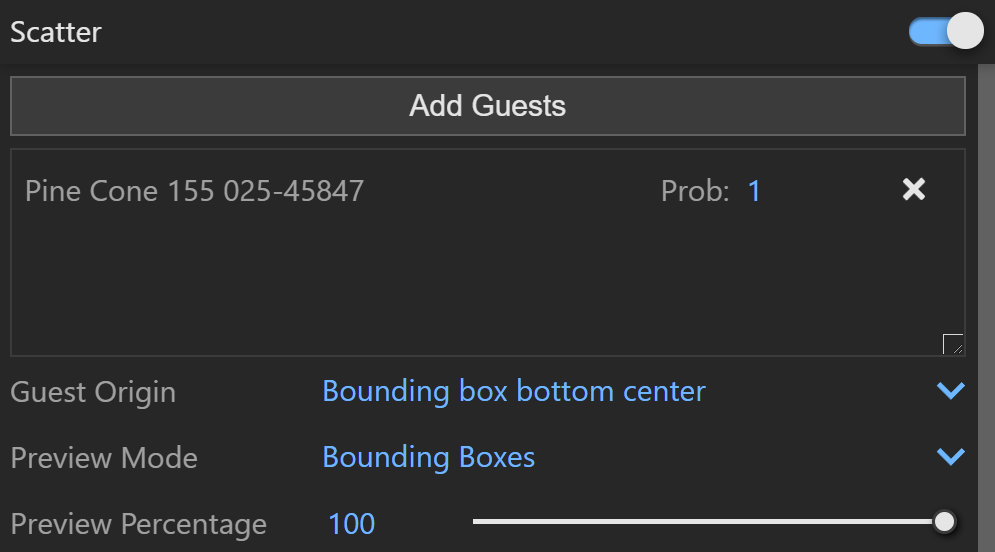
Scatter – Enables Scatter.

Add Guests – Adds the currently selected scene objects to the Guests list. The objects in this list are scattered on the base geometry.

Probability  Determines the relative probability of the guest to appear. For more information see the Probability Example below.

Guest Origin – Determines how the objects are positioned relative to the random Scatter points.

Bounding box bottom center – The bounding box bottom center of the object.
Bounding box volume center – The bounding box volume center snaps to the instance.
Object origin – The original object origin point snaps to the instance point.

Preview Mode – Changes between a bounding box or point preview for the instances. Note that the point positions are determined by the origin of the guest.

Preview Percentage – Limits the number of previews displayed in the viewport.


SketchUp2023_VRay6.2_Scatter_Guest_Parameters


Probability Example


This is an example of introducing multiple Guest objects with different probability settings to one Host object.


Scatter_Asset_Editor_Guest_List


Parameters


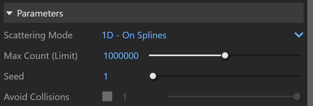
Scattering Mode – Specifies the guest objects scattering mode.

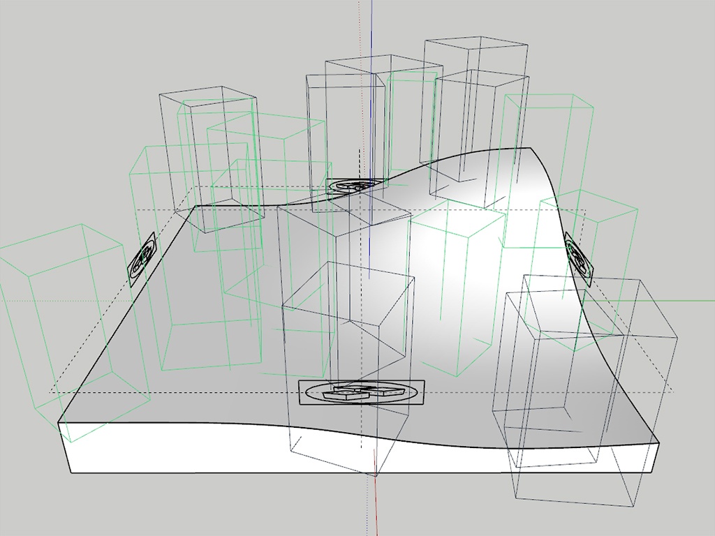
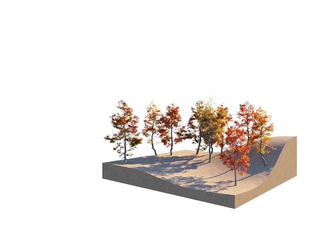
1D - On Splines – Objects are scattered along splines. When a mesh is added to the guests' list, the items are scattered along all mesh edges.
2D - On Surfaces – Objects are scattered on surfaces. It doesn't matter if the surface is horizontal, vertical, or if it is a complex 3D object
3D - In a Bounding Box – Objects are scattered inside the object's bounding box. Keep in mind that bounding boxes are cube-shaped. Using this mode on a round object, scatters instances in a cube around it. 

Max Count (Limit) – Limits the maximum number of instances.

Seed – Controls the random Scatter seed.

Avoid Collisions – When enabled, instances that would collide with each other get discarded. 


SketchUp2023_VRay6.2_Scatter_Parameters


Spline Scattering


This submenu is only available when the scattering mode is set to 1D - On Splines.

Spacing – Determines the spacing between instances in world units.

Jitter – Randomly jitters instances along the spline. Each instance has Spacing applied on both sides, except the instances at the end of the spline. The Jitter value is divided between those two Spacings. In order to allow instances to jitter in all their Spacing distance, the Jitter needs to be set to 2.

Offset – Determines what percentage of the Spacing instances are offset in one direction of the spline. When set to 1, all instances replace the one after them, as the offset is equal to the whole value of the Spacing.

Follow spline – Determines how scattered instances are oriented along the spline. Assigning a value of 1, makes instances follow the spline and are oriented along the local tangent direction.


SketchUp2023_VRay6.2_Scatter_Parameters_Spline


Surface Scattering


This submenu is only available when the scattering mode is set to 2D - On Surfaces.

Mode – Specifies the surface scattering mode.

Random Distribution – Scatters instances randomly on all mesh objects.
UV Grid – Uses UV mapping to scatter instances in regular patterns.


Random Distribution

Instances Count – Gives the total number of instances on all Host objects. Note that adding Area Modifiers or defining Slope Limitation will decrease this number. If the Per Area option is enabled, the scattering is defined by the density.

Per Area – When enabled, the number of instances is determined by the count combined with the size of the host's surface. The value specifies the length of the distribution area's side/edge. If the Count value is set to 1, this number determines the relative density of the instances.

Density – Determines the approximate count of instances based on texture input. Black color in the texture discards all instances in the respective area. Areas colored with white receive the maximum number of instances.

Map Channel – Determines the UV channel.


SketchUp2023_VRay6.2_Scatter_Parameters_Surface


UV Grid

UVs should be set correctly on every surface, not on the whole object.

Pattern – Determines a pattern to use for grid scattering.

Grid – Rectangular grid.
Running Grid – Rectangular grid with every other row offset by half of the grid spacing.
Hexagonal Grid Arranges the instances into hexagons.

Map Channel – Determines the UV channel.

Spacing – Scales the pattern in UV space. When Spacing is set to 1, the pattern occupies the whole space. When Spacing is set to 0.5, the pattern is repeated twice.

Jitter – Determines what percentage of the instances are randomly placed. When Jitter is set to 0, all instances are placed according to the UVW mapping. When Jitter is set to 100, all instances are randomly placed.

Offset – Offsets the pattern by the given value (in percentages). Keep in mind that 0 and 1 Offset give the same result, as 1 moves the pattern by one whole repetition.

Lock – When enabled the values of the V coordinate for Spacing, Jitter and Offset are locked to the U coordinate's values.


SketchUp2023_VRay6.2_Scatter_Parameters_Surface_UVGrid


Slope Limitation

Limits scattering only to 'slopes' at certain angles. The lower the angle range is set, the smaller the angle at which scattering stops.

Local – The slope limitation is measured according to the up vector of each individual guest object. See the Slope Limitation orientation Example.
World – The Slope Limitation for all guest objects is measured relative to world up vector. See the Slope Limitation orientation Example.

Angle From – The lower limit of the range outside which instances get filtered out. See the Slope Limitation Angle Example.

Angle To – The upper limit of the range outside which instances get filtered out. See the Slope Limitation Angle Example.


SketchUp2023_VRay6.2_Scatter_Parameters_SlopeLimitation


Slope Limitation Angle Example

The Slope Limitation Angle removes instances based on the angle of the underlying geometry. This option can be used to remove geometry from steep areas as well as shallow areas.


Angle From = 0.0, Angle To = 45.0

Angle From = 0.0, Angle To= 20.0

Angle From = 5.0, Angle To = 20.0


Slope Limitation orientation Example

The Local and World Slope Limitations determine the up-vector. The Local option uses the up vector of each individual guest object. The World option uses the world up vector of the scene. In this example, the Slope Limitation Angle is set to 0.0-45.0.


Local Before image
World After image


Bounding Box Scattering


This submenu is only available when the scattering mode is set to 3D -  In a Bounding Box.

Instances Count – Gives the total number of instances on all Host objects. Note that adding Area Modifiers or defining Slope Limitation will decrease this number. If the Per Cubic Volume option is enabled, the scattering is defined by the density.

Per Cubic Volume – When enabled, the number of instances is determined by the count combined with the size of the host's bounding box volume. The value specifies the length of the distribution cube's side/edge. If the Count value is set to 1, this number determines the relative density of the instances.


SketchUp2023_VRay6.2_Scatter_Parameters_BoundingBox


Transforms


Random Translation


Moves the instances From the given distance To the given distance on the corresponding axis. A map can be attached. If the map is enabled, it overwrites the translation values. RGB maps can be used to control translations in specific axes (Red = X; Green = Y; Blue = Z). Grayscale maps control all axes proportionally.

Step Size – Specifies the random step size.


SketchUp2023_VRay6.2_Scatter_Parameters_RandomTransition


Random Rotation


Rotates the instances From the given degrees up To the given degrees continuously. A map can be applied. If it is enabled for a given axis, its rotation values are overwritten by the map. RGB maps can be used to control the rotation of each axes individually ( Red = X; Green = Y; Blue = Z). Grayscale maps control the rotation of all axes proportionally.

Step Size – Specifies the random step size.

Normal Alignment – When a value, different than 0 is entered, the instances are aligned according to the world up axis. This is useful when the host object is curved and the scattered objects need to remain vertical, not follow the curve of the surface. Positive values mean that the instances are aligned to the +Z axis (vertical up) and negative values mean that the instances are aligned to the -Z axis (vertical down).

Preserve Rotation – Preserves the original rotation of the objects.


SketchUp2023_VRay6.2.2_Scatter_Parameters_RandomRotation

Random Scale


Scales the instances From the given value To the given value continuously. When Uniform scale is enabled, the X axis values are applied on the whole Distribute-on target object. A map can be applied. If it is enabled for an axis, the values of that axis are overwritten. RGB maps can be used to scale axes individually ( Red = X; Green = Y; Blue = Z). Grayscale maps control the scale of all axes proportionally.

Step Size – Specifies the random step size.

Uniform Scaling – When enabled the X axis values are also used for the Y and Z axes.

Preserve Scaling – Preserves the original scaling of the objects. 


SketchUp2023_VRay6.2_Scatter_Parameters_RandomScale


Area Modifiers


Add Modifier – Specifies objects to be used for generating projected areas of exclusion or inclusion of Scatter guests. These areas are projected along specified axes and determined by the dimensions of objects or splines included in this list. Scatter Area Modifier objects cannot be the same as the Scatter Host objects. Note that Area Modifiers are available only in Surface and Volume Scatter modes.

Operation 

Include – only instances within the projected area are created.
Exclude – only instances outside the projected area are created.

Axis – Determines the plane of the area modifier projection along the X, Y or Z axis.

Falloff Near – Determines the distance from the selected area modifier object where the falloff begins its effect. The falloff range is the gradual fading of the area modifier effect between 100% and 0%.

Falloff Far – Determines the distance from the selected area modifier object where the falloff range ends and the area modifier loses effect.

Scale – Scale factor affecting instances between the Near and Far Falloff distances. The value represents the effect strength at the end of the falloff range.
For example, a value of 0.5 causes instances to have a scale of 0% at the Falloff Near distance gradually increasing to 50% at the Falloff Far distance. Note that a value of 0 negates the falloff effect altogether.

Density – Density factor affecting instances between the Near and Far Falloff distances. The value represents the effect strength at the end of the falloff range. For example, a value of 0.5 causes instances to appear at a density of 0% at the Falloff Near distance gradually increasing to 50% at the Falloff Far distance. Note that a value of 0 negates the falloff effect altogether.

Offset Area Modifier objects that obstruct your view by moving them along their projection axis. This way they produce the same effect but are out of sight.


SketchUp2023_VRay6.2_Scatter_Parameters_AreaModifiers


Notes


  • V-Ray 6 provides the option for multiple special objects to be added in combination with a single group/component. This allows for Fur, Scatter, and Displacement special objects to be used simultaneously. Multiple Fur and Scatter assets can be added to a single object.
  • Special objects can be removed from geometry by double-clicking on the group/component, selecting the special object's widget, and then selecting the Erase option from the context menu (right-click to open the context menu).
  • When Mesh Light or Clipper are applied, no other special objects are allowed.
  • The Scatter Density map currently does not support raytraced textures.
  • Curve objects need to be grouped via G shortcut on windows or command + G on macOS to be added as Scatter Area Modifiers.
  • If Scatter is applied to a spline closing a face, its segments (edges of the face) are treated as individual splines.
  • Apply a material with 0 opacity for host objects that you don’t want visible in the rendered image.