![]()
Page History
...
| Section | |||||||||||||||
|---|---|---|---|---|---|---|---|---|---|---|---|---|---|---|---|
|

UI Options
...
| Section | ||||||||||||||||||||
|---|---|---|---|---|---|---|---|---|---|---|---|---|---|---|---|---|---|---|---|---|
|

...
Parameters
...
| Section | |||||||||||||||
|---|---|---|---|---|---|---|---|---|---|---|---|---|---|---|---|
|

| Anchor | ||||
|---|---|---|---|---|
|
...
| Section | |||||||||||||||
|---|---|---|---|---|---|---|---|---|---|---|---|---|---|---|---|
|

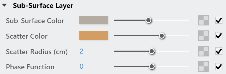
Sub-Surface Layer
...
| Section | |||||||||||||||
|---|---|---|---|---|---|---|---|---|---|---|---|---|---|---|---|
|
| Anchor | ||||
|---|---|---|---|---|
|
...
| Anchor | ||||
|---|---|---|---|---|
|
...
Example: Scatter Color
The The Sub-Surface Color is set to green for all the following renders.
| Section | |||||||||||||||||||||||||||||||||||
|---|---|---|---|---|---|---|---|---|---|---|---|---|---|---|---|---|---|---|---|---|---|---|---|---|---|---|---|---|---|---|---|---|---|---|---|
| |||||||||||||||||||||||||||||||||||
|


...
| Section | |||||||||||||||
|---|---|---|---|---|---|---|---|---|---|---|---|---|---|---|---|
|

Scattering Options
...
| Section | |||||||||||||||
|---|---|---|---|---|---|---|---|---|---|---|---|---|---|---|---|
|

| Anchor | ||||
|---|---|---|---|---|
|
...
| Section | |||||||||||||||
|---|---|---|---|---|---|---|---|---|---|---|---|---|---|---|---|
|

Override Control
...
...
| Section | |||||
|---|---|---|---|---|---|
|
...
|

App.Man.
Attributes
...
The attributes from the following expandable menus are available for the Subsurface Scattering materialAttributes available for the Subsurface Scattering material are as follows.
| Anchor | ||||
|---|---|---|---|---|
|
| Expand | |||||||||
|---|---|---|---|---|---|---|---|---|---|
| |||||||||
Bump
|
| Expand | 60% | |||||||||||||||||||
|---|---|---|---|---|---|---|---|---|---|---|---|---|---|---|---|---|---|---|---|---|
Mode/Map – Specifies the bump map type. Bump Map – A height map should be used. Amount – Multiplier for the bump/normal map. Delta Scale – Specifies a scale for sampling the bitmap when using bump mapping. The exact value is calculated automatically by V-Ray, but can be called here. |
| Column | ||
|---|---|---|
| ||
|
| Column | ||
|---|---|---|
| ||
| title | Contour |
|---|
Contour
| Section | ||||||||||||||||||||
|---|---|---|---|---|---|---|---|---|---|---|---|---|---|---|---|---|---|---|---|---|
|
| title | Displacement |
|---|
Displacement
| width | 60% |
|---|
| UI Text Box | ||
|---|---|---|
| ||
This is a legacy attribute that will be removed in the future. Consider using the geometry displacement modifier instead. It can be created as a geometry asset in the Outliner and can be applied to objects in the scene. Note that the displacement effect will no longer appear in the Preview Swatch. |
Displacement – Enables or disables the displacement effect.
Mode/ Map – Specifies the mode in which the displacement is rendered.
2D Displacement – Bases the displacement on a texture map that is known in advanced. The displaced surface is rendered as a warped height-field based on that texture map. The actual raytracing of the displaced surface is done in texture space and the result is mapped back into 3D space. The advantage of this method is that it preserves all details in the displacement map. However, it requires the object to have valid texture coordinates. You cannot use this method for 3d procedural textures or other textures that use object or world coordinates. The parameter can take any values.
Normal Displacement – Takes the original surface geometry and subdivides its triangles into smaller sub-triangles, which then are displaced.
Amount – The amount of displacement. A value of 0.0 means the object appears unchanged. Higher values produce a greater displacement effect. This parameter can also take a negative value, in which case the displacement pushes geometry inside the object.
Shift – Specifies a constant, which is added to the displacement map values, effectively shifting the displaced surface up and down along the normals. This can be either positive or negative.
Keep Continuity – When enabled, tries to produce a connected surface, without splits, when there are faces from different smoothing groups and/or material IDs. Note that using material IDs is not a very good way to combine displacement maps since V-Ray cannot always guarantee the surface continuity. Use other methods (vertex colors, masks etc.) to blend different displacement maps.
Resolution – This option is available when the Mode/Map is 2D Displacement. It determines the resolution of the displacement texture used by V-Ray. If the texture is a bitmap, it is recommended to match this resolution to the size of the bitmap. For procedural 2D maps, the resolution is determined by the desired quality and detail in the displacement. Note that V-Ray also automatically generates a normal map based on the displacement map in order to compensate for details not captured by the actual displaced surface.
View Dependent – When enabled, Edge Length determines the maximum length of a subtriangle edge in pixels. A value of 1.0 means that the longest edge of each subtriangle is about one pixel long when projected on the screen. When disabled, Edge Length is the maximum sub-triangle edge length in world units.
Edge Length – Determines the quality of the displacement. Each triangle of the original mesh is subdivided into a number of subtriangles. More subtriangles mean more detail in the displacement, slower rendering times and more RAM usage. Less subtriangles mean less detail, faster rendering and less RAM. The meaning of Edge length depends on the View Dependent parameter. The slider's minimum range is set to 0.4. Using lower values is still possible by manually typing them in the input box but it may cause significant render delay.
Max Subdivs – Controls the maximum sub-triangles generated from any triangle of the original mesh when the displacement type is Subdivision. The value is in fact the square root of the maximum number of subtriangles. For example, a value of 256 means that at most 256 x 256 = 65536 subtriangles will be generated for any given original triangle. It is not a good idea to keep this value very high. If you need to use higher values, it will be better to tessellate the original mesh itself into smaller triangles instead. The actual subdivisions for a triangle are rounded up to the nearest power of two (this makes it easier to avoid gaps because of different tessellation on neighboring triangles).
Water Level – Clips the surface geometry in places where the displacement map value is below the specified threshold. This can be used for clip mapping a displacement map value below which geometry will be clipped.
Level Height – Value below which the geometry is clipped.
| UI Text Box | ||
|---|---|---|
| ||
Materials need to be applied to objects (groups/components) to have working displacement. If various materials are applied to different faces of an object, the displacement from the top-level (group/component) material will be used on all of them. Normal Displacement will take into account the texture size of each different face material, while 2D Displacement will ignore them. |
| Column | ||
|---|---|---|
| ||
|
| Column | ||
|---|---|---|
| ||
| title | Raytrace Properties |
|---|
Raytrace Properties
| Section | |||||||||||||||
|---|---|---|---|---|---|---|---|---|---|---|---|---|---|---|---|
|
| title | Override |
|---|
Override
| Section | |||||||||||||||
|---|---|---|---|---|---|---|---|---|---|---|---|---|---|---|---|
|
| title | Material ID |
|---|
Material ID
| Column | |||||
|---|---|---|---|---|---|
| |||||
ID Number – Isolates objects as an R/G/B mask in the MultiMatte Material render elements. ID Color – Allows you to specify a color to represent this material in the Material ID VFB render element.
|
| Column | ||
|---|---|---|
| ||
|
| width | 35% |
|---|
| title | Outline |
|---|
Outline
| Multiexcerpt include | ||||
|---|---|---|---|---|
|
| Expand | ||||||
|---|---|---|---|---|---|---|
| ||||||
Displacement
|
| Expand | ||||||
|---|---|---|---|---|---|---|
| ||||||
Raytrace Properties
|
| Expand | ||||||
|---|---|---|---|---|---|---|
| ||||||
Override
|
| Expand | ||||||
|---|---|---|---|---|---|---|
| ||||||
Material ID
|
Notes
...
| Fancy Bullets | ||
|---|---|---|
| ||
|
...