![]()
Page History
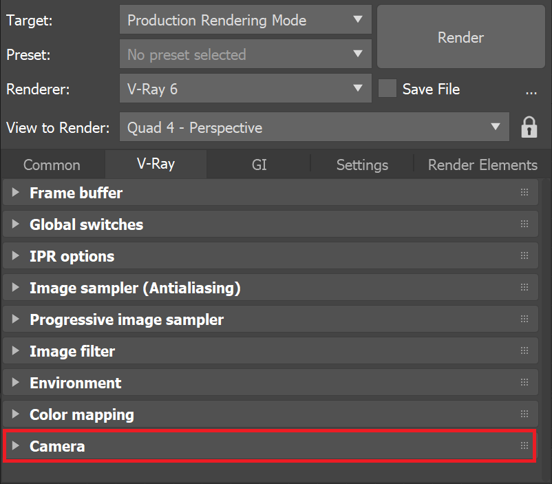
This page provides information on the Camera rollout in under the V-Ray tab of the Render Settings.
Overview
...
| Section | |||||||||||||||
|---|---|---|---|---|---|---|---|---|---|---|---|---|---|---|---|
|
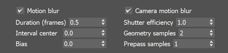
Parameters
...
The cameras in V-Ray generally define the rays that are cast into the scene, which essentially is how the scene is projected onto the screen. V-Ray supports several camera types: Standard, Spherical, Cylindrical (point), Cylindrical (ortho), Box, Fish eye, Warped sphere, Spherical panorama, and Cube 6x1. Orthographic views are supported too.
| Section | |||||||||||||||||||||||||||||||||||||||
|---|---|---|---|---|---|---|---|---|---|---|---|---|---|---|---|---|---|---|---|---|---|---|---|---|---|---|---|---|---|---|---|---|---|---|---|---|---|---|---|
|

| Anchor | ||||
|---|---|---|---|---|
|
...
Example: Camera Types
The following images below show the difference between the different camera types:
...
| Section | ||||||||||||||||||||
|---|---|---|---|---|---|---|---|---|---|---|---|---|---|---|---|---|---|---|---|---|
|
| Anchor | ||||
|---|---|---|---|---|
|
...
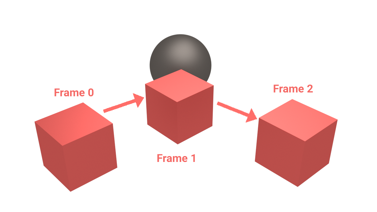
The following scene consists of three-frame animation of a moving cube. In the first frame the cube is on the left. In the second frame it is at the sphere. And in the third frame the cube is on the right.
| Section | |||||||||||||||
|---|---|---|---|---|---|---|---|---|---|---|---|---|---|---|---|
|
...
| Section | ||||||||||||||||||||
|---|---|---|---|---|---|---|---|---|---|---|---|---|---|---|---|---|---|---|---|---|
|

Notes
...
| Fancy Bullets | ||||||
|---|---|---|---|---|---|---|
| ||||||
|