![]()
Page History
...
| Section | |||||||||||||||
|---|---|---|---|---|---|---|---|---|---|---|---|---|---|---|---|
|

...
| Anchor | ||||
|---|---|---|---|---|
|
...
| width | 25% |
|---|
...
| width | 50% |
|---|
Example: Mode
This example shows the difference between Random Distribution and UV Grid modes. The scene for this example is set in inches.
| Before after | ||||||||||||||||||||||||||||
|---|---|---|---|---|---|---|---|---|---|---|---|---|---|---|---|---|---|---|---|---|---|---|---|---|---|---|---|---|
| center
| panel
| align
| |||||||||||||||||||||||||
|

Random Distribution
...
| Section | |||||||||||||||
|---|---|---|---|---|---|---|---|---|---|---|---|---|---|---|---|
|

...
| Section | ||||||||||||||||||||||||||||||||||||||
|---|---|---|---|---|---|---|---|---|---|---|---|---|---|---|---|---|---|---|---|---|---|---|---|---|---|---|---|---|---|---|---|---|---|---|---|---|---|---|
| ||||||||||||||||||||||||||||||||||||||
| Section | ||||||||||||||||||||||||||||||||||||||
|


...
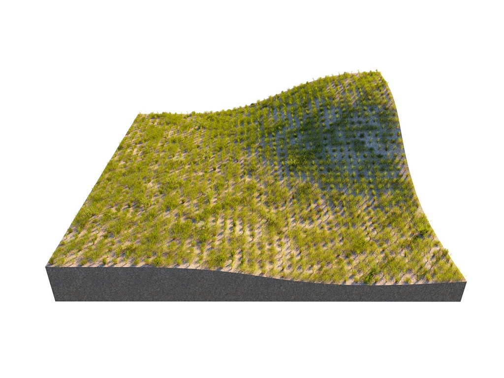
Example: Density Map
Using a Density map generates brand new instance distribution. The total number of instances (approximate to the 'Instance Count' value) is preserved and distributed on all surfaces that correspond to map values above 0 (parts of the map not being purely black). Instances are more likely to be generated in areas with higher Density map values than darker ones. The scene for this example is set in inches.
| Before after | ||||||||||||
|---|---|---|---|---|---|---|---|---|---|---|---|---|
| align
| center | ||||||||||
| ||||||||||||
| Column | ||||||||||||
|
| |||||||||||
|


UV Grid
...
| Section | |||||||||||||||
|---|---|---|---|---|---|---|---|---|---|---|---|---|---|---|---|
|

...
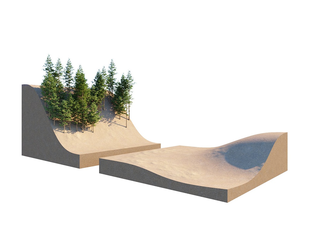
This example shows how a group of multiple guest objects can be distributed over several more than one host object. The scene for this example is set in inches.
| Sectionbefore-after | |||||||||||||||||||||||||||||
|---|---|---|---|---|---|---|---|---|---|---|---|---|---|---|---|---|---|---|---|---|---|---|---|---|---|---|---|---|---|
| width
| 20%
| column
| width
| 60
| ||||||||||||||||||||||||
|

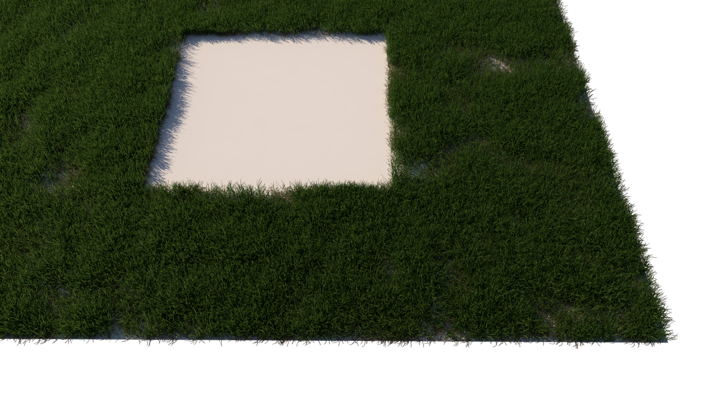
Edge Trimming
...
| Section | |||||||||||||||
|---|---|---|---|---|---|---|---|---|---|---|---|---|---|---|---|
|

...
Example: Edge Trimming
| Alignbefore-after | |||||||||
|---|---|---|---|---|---|---|---|---|---|
| LabelBefore |
| ||||||||
| Image_comparison_slider |
|
| |||||||
width
| |||||||||
| AttachmentImageBefore | edge_trimming-not_trimmed.png | ||||||||
| AttachmentImageAfter | edge_trimming-trimmed.png | height |

| Panel | ||
|---|---|---|
| ||
|
Notes
...
| Fancy Bullets | ||||||
|---|---|---|---|---|---|---|
| ||||||
|
...