The V-Ray Rectangle light is a planar light source with the shape of a rectangle or circular disc.
Overview
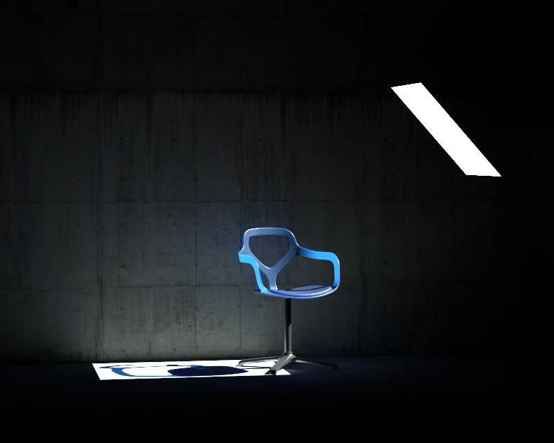
The VRayLightRect, also known as the V-Ray Rectangle light or an "area light" is a planar light source. The light's shape can be set as a rectangle or a circular disc.

Image © Yuki Sugiyama
UI Paths
Create menu > Lights > V-Ray Rect Light
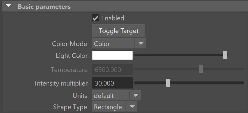
Basic Parameters
Enabled – Turns the VRayLightRect on and off.
Toggle Target – Switches the light between being targeted and not targeted (free light). The Maya default hotkey T can also be used.
Color Mode –The mode in which the color of the light will be specified, either Color or Temperature.
Light Color – When Color Mode is set to Color, this color controls the color of the light. When using photometric units, this color is normalized so that only the color hue is used and the light intensity is determined by the Intensity multiplier.
Temperature – When the Color Mode is set to Temperature, this parameter controls the color of the light by degrees Kelvin.
Intensity multiplier – Multiplier for the light color; this is also the light intensity in the units set by the Units parameter.
Units – Choose the light units. Using correct units is essential when using the VRayPhysicalCamera. The light will automatically take the scene's unit scale into consideration to produce the correct result for the scale you are working with. The possible values are:
default – The color and multiplier directly determine the visible color of the light without any conversion. The light surface will appear with the given color in the final image when seen directly by the camera (assuming there is no color mapping involved).
Lumens – Total emitted visible light power measured in lumens. When this setting is used, the intensity of the light will not depend on its size. A typical 100W electric bulb emits about 1500 lumens of light.
lm/m/m/sr – Visible light surface power measured in lumens per square meter per steradian. When this setting is used, the intensity of the light depends on its size.
Watts – Total emitted visible light power measured in watts. With this setting, the intensity of the light does not depend on its size. Keep in mind that this is not the same as the electric power consumed by a light bulb for example. A typical 100W light bulb only emits between 2 and 3 watts as visible light.
w/m/m/sr – Visible light surface power measured in watts per square meter per steradian. When this setting is used, the intensity of the light depends on its size.
Shape Type – Specifies the light shape.
Rectangle – The VRayLightRect has the shape of a planar rectangle.
Disc – The VRayLightRect has the shape of a planar disc.
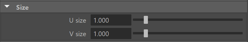
Size
U Size – Determines the width of the light measured in scene units. The width will be twice this value.
V Size – Determines the height of the light measured in scene units. The height will be twice this value.
Using the size parameters is the recommended method for controlling the light's size. Avoid scaling the light. Uniform scaling can be used when the scene needs to be scaled up or down, but non-uniform scaling produces skewed or elliptical shapes, which may produce incorrect results.
Directionality
Directional – When this value is 0, the light from the VRayLightRect is spread out equally in all directions. Increasing this value makes the light beam more narrow and concentrates it in one direction. For more information, see the Directional Spread example below.
Directional Preview Length – Specifies the length of the cone used to preview the Directional parameter in the viewport. This parameter is available only when Directional is greater than 0.
Directional Preview – Controls the appearance of the preview of the directional effect in the viewport. This parameter is available only when Directional is greater than 0.
Selected – The preview is displayed only when the light is selected.
Always – The preview is always displayed.
Never – The preview is never displayed.

Example: Directional Spread
The Directional parameter controls the spread of the Plane or Disc light. A value of 0 produces the maximum spread of light in all directions as seen below left, while a value of 1 creates a narrow 90-degree cone of light as seen below right.

Plane light with Directional = 0, 0.5, 1.0
Directional Preview = Always
This example demonstrates how the light changes when Directionality value is changed, ranging from 0 to 1. When the value is closer to 1, the light is more focused towards one point, while when the value is closer to 0, the light spreads to all sides.

Directionality = 0.0

Directionality = 0.25

Directionality = 0.50

Directionality = 0.75
Directionality = 1.0
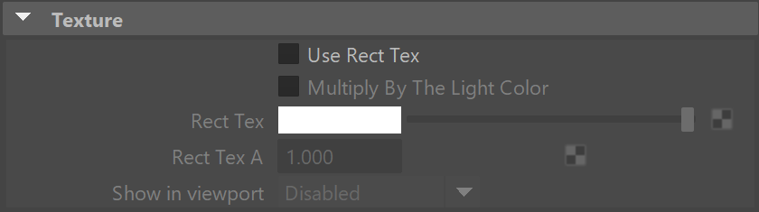
Texture
Use Rect Tex – Enables the light to use a texture for the light surface. It is best to have GI enabled if there are surfaces that are close to a texture-mapped light. This allows V-Ray to use combined direct and indirect sampling for the light, reducing the noise for surfaces close to the light.
Multiply By The Light Color –When enabled, the colors in the texture are multiplied by the light intensity to adjust the brightness.
Rect Tex – Specifies the texture to use for the light. Note: If an RGBA texture file (a file that contains an alpha channel) is used, the file's alpha output must be connected to the Rect Tex A attribute to utilize the alpha channel on the light.
Rect Tex A – Specifies an alpha texture for the light. Note: The default value of 1 (fully opaque) remains unchanged whenever a file texture is connected to the Rect Tex attribute, even if that file contains an alpha channel. For a file's alpha channel to be utilized, it's alpha output needs to be connected to this attribute.
Show in viewport – Controls whether, and how, the texture is seen in the viewport.
Disabled – The texture is not displayed.
Texture only – The texture is displayed.
Texture*Intensity – The texture is multiplied by the light intensity before it is displayed.
Options
No Decay – Normally the light intensity is inversely proportional to the square of the distance from the light (surfaces that are farther from the light source receive less light than surfaces which are closer to the light). When this option is enabled, the light's intensity does not decay with distance. See the example under VRayLightSphere to see this demonstrated. This option is inactive when using the V-Ray CUDA engine.
Double Sided – When enabled, light emits from both sides of the plane. For more information, see the Single-Sided vs Double-Sided Lights example below.
Invisible – Controls whether the shape of the VRayLightRect source is visible in the render result. When this option is enabled, the light source is not visible in the rendering. When this option is disabled, if the light source is seen directly by the camera or through refractions, it appears in renderings in the current light color.
Note: The visibility of the light with respect to reflections is controlled by the Affect Specular and Affect Reflections options rather than the Invisible parameter.
Skylight Portal – When enabled, the Light Color and Intensity multiplier parameters are ignored; instead the light will take its intensity from the environment behind it. See the Skylight Portal example below.
Simple Skylight Portal – This option is available only when the Skylight Portal option is enabled. This option can speed up rendering by simplifying the process of tracing the environment for the skylight portal. When enabled, the VRayLightRect uses all the environment color, not just the color from objects behind the light. Using just the environment behind the light requires additional rays, so using the entire environment makes the rendering of portal lights faster.
Affect Diffuse – Determines whether the light affects the diffuse properties of the materials.
Affect Specular – Determines whether the light affects the specular of the materials. This means glossy reflections.
Affect Reflections – Determines whether the light appears in reflections of materials, both perfect and glossy reflections.
Diffuse contribution – A multiplier for the effect of the light on the diffuse component.
Specular contribution – A multiplier for the effect of the light on the specular component.
Example: Double-Sided Lights
This example demonstrates the behavior of the light when Double Sided option is enabled and disabled. When the Double Sided option is enabled, light is emitted from the two sides of the Rectangle light body.
Example: Skylight Portal
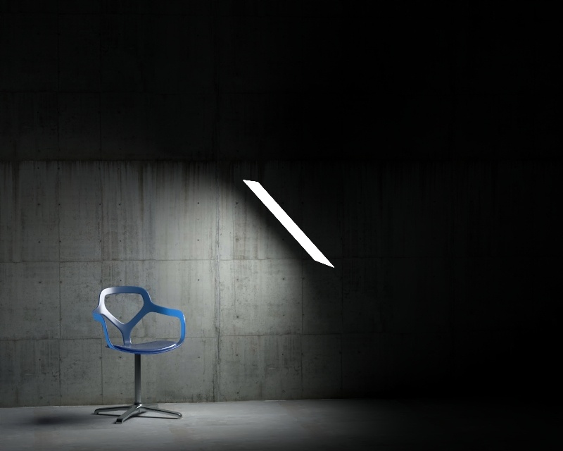
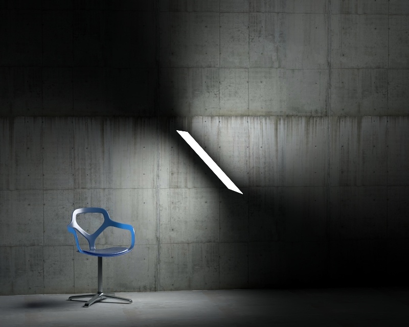
This example demonstrates the behavior of the Skylight Portal option. Generally, using the Skylight Portal option optimizes the render speed and the light in the scene. Notice how disabling this option produces much darker result inside the house.
Skylight Portal is Disabled
Simple Skylight Portal is Enabled
Skylight Portal is Disabled, a Dome light is used
Sampling
Subdivs – This parameter is disabled by default since most users will not need local control of subdivs, however, this parameter controls the number of samples V-Ray takes to compute lighting locally for this light. Lower values create more noise but render faster. Higher values produce smoother results but take more time to render. Note that the actual number of samples also depends on the Sampler settings. By default, this parameter is controlled by the Min Shading Rate in the image sampler. This parameter is not available when the renderer is set to CUDA.
To activate this parameter and specify a value, use the Use Local Subdivs parameter under the V-Ray > DMC Sampler tab in the Render Settings window.
Light cut-off threshold – Specifies a threshold for the light intensity, below which the light will not be computed. This can be useful in scenes with many lights, where you want to limit the effect of the lights to some distance around them. Larger values cut away more of the light; lower values make the light range larger. When this value is 0.0, the light is calculated for all surfaces. This parameter is not available when the renderer is set to CUDA.
Override motion blur samples – When enabled, the Motion blur samples value overrides the default number of samples used to sample the current light for motion blur.
Motion blur samples – Number of samples used to sample the current light for motion blur.
Texture Resolution –
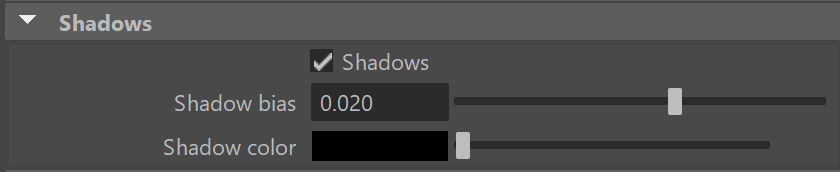
Shadows
Shadows – When enabled (the default), the light casts shadows. Disable this option to turn off shadows for the light.
Shadow bias – Moves the shadow toward or away from the shadow-casting object (or objects). Higher values move the shadow toward the object(s), while lower values move it away. If this value is too extreme, shadows can "leak" through places they shouldn't or "detach" from an object. Other effects from extreme values include Moire patterns, out-of-place dark areas on surfaces, and shadows not appearing at all in the rendering.
Shadow Color – Controls the color of shadows for this light. Note that anything different from black is not physically correct. This option is inactive when using the V-Ray CUDA engine.
Photon Emission
This rollout is inactive when using the V-Ray CUDA engine.
Caustics subdivs – Only used when calculating Caustics. Lower values mean more noisy results but will render faster. Higher values produce smoother results but take more time.
Caustics multiplier – This value is a multiplier for the generated caustics by the selected object. Note that this multiplier is cumulative - it does not override the multiplier in the Caustics render roll-out section.
Photon Subdivs and Diffuse Multiplier parameters no longer show in the UI, as they are related to the Photon Map GI engine, which is deprecated. They are still accessible through script.
Parameters - UI
Locator scale – Multiplies the size of the locator in the viewport. This does not affect the rendering.
Disabling MIS may increase noise, especially in glossy reflections. Only disable it when you have a reason to.
Parameters - Advanced Options
Use MIS – Enables Multiple Importance Sampling for the light. When MIS is enabled (the default), the light's contribution is split between direct illumination on the one hand and GI (for diffuse materials) or reflections (for glossy surfaces) on the other. This means that portions of the light's contribution will end up in the GI render elements (or the reflection render elements respectively). In certain specific situations, this is undesirable and this option can be used to always calculate the light contribution through direct illumination.