The instructions on this page guide you through the process of creating a flamethrower using Chaos Phoenix 4, Particle Flow and V-Ray 5 .
Overview
This Advanced Level tutorial guides you through Phoenix simulation settings and the final shot setup. It's recommended that you have at least basic knowleage in lighting, materials, and the Phoenix simulation. Understanding of Particle Flow is beneficial but not required.
In this tutorial, we show how Phoenix works together with Particle Flow (PFlow).
Particles are generated by using 3ds Max's PFlow. There are two particle systems in the scene. One for the main flame of the flamethrower and another for the fire dripping from the main flame.
PFlow's particles contain velocity data and Phoenix can use it as a source for fire and smoke to produce realistic flamethrower. This effect can be also used for dragon breathing fire simulation.
We take advantage of the Time Base - Particle Age, a powerful feature of the Fire/Smoke Source. It allows you to animate the emission of fluid based on the age of each individual particle.
This simulation requires Phoenix 4.30 Official Release and V-Ray 5 Official Release for 3ds Max 2017 at least. You can download official Phoenix and V-Ray from https://download.chaos.com. If you notice a major difference between the results shown here and the behavior of your setup, please reach us using the Support Form.
Press the Download button below to get an archive with the start and end scenes.
To download project files: Download Project Files
Want to follow along but don’t have a license?: Download Free Trial
Units Setup
Scale is crucial for the behavior of any simulation. The real-world size of the Simulator in units is important for the simulation dynamics.
Large scale simulations appear to move slower, while mid-to-small scale simulations have lots of vigorous movements.
When you create your Simulator, you must check the Grid rollout where the real-world extents of the Simulator are shown. If the size of the Simulator in the scene cannot be changed, you can cheat the solver into working as if the scale is larger or smaller by changing the Scene Scale option in the Grid rollout.
The Phoenix solver is not affected by how you choose to view the Display Unit Scale - it is just a matter of convenience.
As the focus of this tutorial is a large-scale simulation, setting the units to Meters is a reasonable choice.
Go to Customize → Units Setup and set Display Unit Scale to Metric Meters. Also, set the System Units such that 1 Unit equals 1 Meter.

Scene Layout
The final scene consists of the following elements:
- Two Particle Flow nodes: PF Source_main_flame and PF Source_dripping_fire;
- Phoenix Fire/Smoke Simulator;
- There are two Phoenix Fire/Smoke Sources: one for the main_flame, another for the dripping_fire;
- V-Ray Light Dome for environment lighting; VRay Sun as key light;
- V-Ray Physical Camera for rendering;
- Plane-ground as ground plane;
- A soldier geometry holding the flamethrower. Also helps by creating a sense of scale in the scene;
- Phoenix Turbulence force;
- Drag force to slow down the Particle Flow's particles;
- Two Gravity forces: one for the main_flame particle, another one for the dripping fire particles.

In this tutorial we have many steps to follow. To keep it concise, let's focus only on the Phoenix related steps and feel free to use the camera and light settings in the provided sample scene.
For your reference, below you can find the light and camera settings.
Camera Setting
Add a Command Panel → Cameras → V-Ray → VRayPhysicalCamera.
The exact position of the Camera is XYZ: [ 4.5, -35.0, 0.5 ].
The exact position of the Camera Target is XYZ: [ 12.0, -1.0, 5.5 ].
Aperture → F-Number is set to 2.4.
Aperture → Shutter Speed is set to 200.
Color & Exposure → White Balance is set to Custom with RGB color (255, 160, 59).

We animate the camera. From frame 0 to frame 90, its position moves from XYZ: [ 4.5, -35.0, 0.5 ] to XYZ: [ 3.2, -35.0, 0.3 ].

Lighting
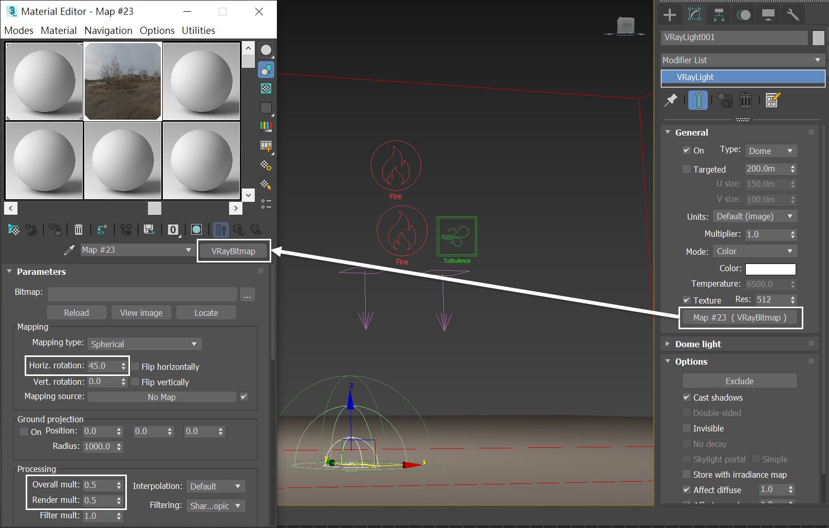
From Command Panel → Light → V-Ray → VRayLight create a V-Ray Light in the scene.
The exact position of the V-Ray Light is XYZ: [ 19.0, -9.0, 0.0 ].
Plug a VRayBitmap map to the map slot.
Set the Horiz. rotation to 45.0.
Decrease both Overall multiplier and Render multiplier to 0.5.
Starting with V-Ray 5, the VRayHDRI map is renamed to VRayBitmap.
From Command Panel → Light → V-Ray → VRaySun, create a VRaySun in the scene.
The exact position of the VRaySun is XYZ: [ 17.8, 0.0, 19.2 ].
Decrease the Intensity multiplier to 0.025.
Enable the Invisible option to avoid any unwanted highlights in your rendering.
VRaySun is the light that enhances the contrast of the smoke coming from the flamethrower. Otherwise, using only the environmental lighting makes the smoke look flat.

Particle Flow Settings
This section contains information about the Particle Flow settings. The setup is not discussed in-depth, it is only provided as a starting point for the Phoenix Simulation.
Here is a preview animation of the particle simulation in its current state.
The main_flame particles are emitted from the PF Source_main_frame, shown in green color.
The dripping fire particles are emitted from PF Source_dripping_fire, shown in orange color.
The green particles are falling because of the Gravity001 force and the orange particles fall with weaker gravity force (the Gravity002). Both particles are influenced by the Drag force for realism.
The Drag force slows down the velocity of particles over time and in this way enhances the realism.
The particle speed for the main_flame is set to 113.5 m. After the fluid simulation, the flame can reach around 25 meters away from the flamethrower's nozzle, which matches data from a real-life flamethrower.
Here is a list of Particle Flow Systems. It summarizes all the different particles, their wireframe color (so you can easily recognize them in the viewport), and for what Fire/Smoke sources are used.
Particle Flow | Wireframe Color | Used for Fire/Smoke Source |
|---|---|---|
PF Source_main_flame | Green | PHXSource_main_flame |
PF Source_dripping_fire | Orange | PHXSource_dripping_fire |
Here is a Particle View of the particle systems. The force operators are highlighted, so you can see which force affects which particles. These forces are used purely for the particle flow, not for fluid simulation.
Note that later in the steps, we have to put those forces in the Simulator's Scene Interaction Exclude list, otherwise, they will influence our fluid simulation.
We have two gravity space wraps in the scene. The strength of Gravity001 is 0.03, and the other Gravity002 is weaker, set at 0.01.
The particle systems we set up here are quite simple and straightforward. You can easily recreate the scene with tyFlow or thinkingParticles, if you want.

For the Speed operator of the PF Source_main_flame, we set the Divergence parameter to 2.0. It controls how much the emitting particles spray out. You can customize your flamethrower by adjusting this parameter.

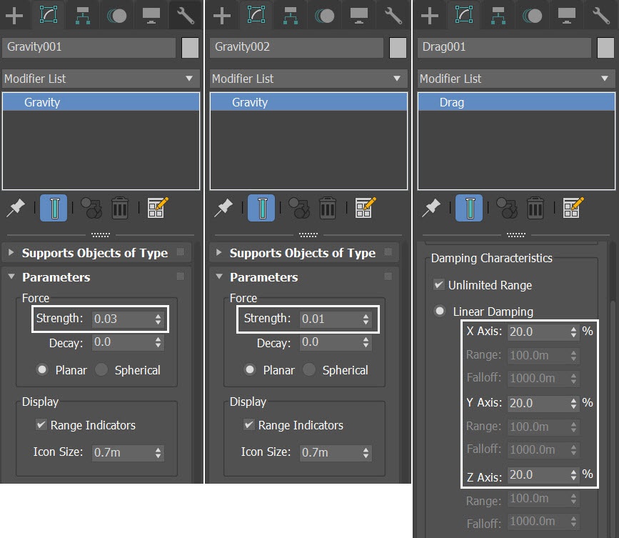
Here are shown screenshots of the three forces in the scene and their parameters.
Gravity001 Strength = 0.03.
Gravity002 Strength = 0.01.
Drag's Linear Damping is set to 20% for all three axes.
Anatomy of the Flamethrower
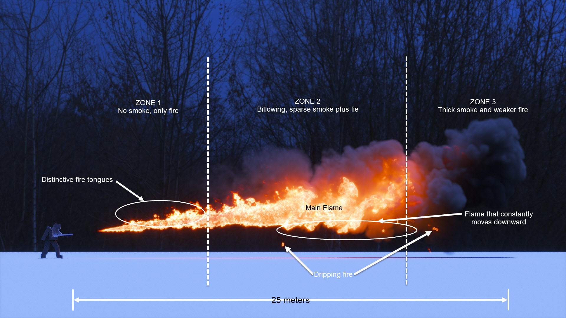
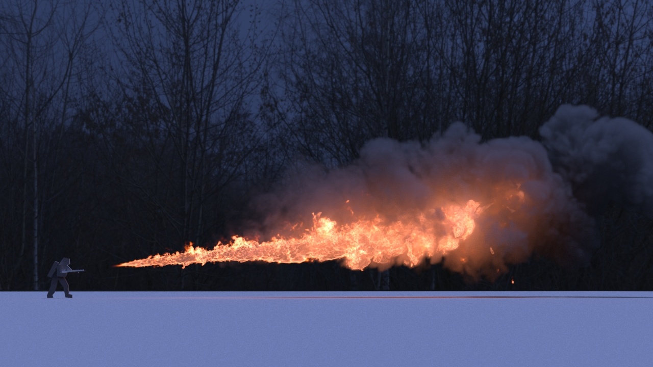
The image here is the final rendering in this tutorial.
This weapon is able to throw a flame more than 25 meters away. The projectile is divided into three zones showing different characteristics of the simulated fluid. Near the flamethrower's nozzle in zone 1, you can see only fire but no smoke.
When the flame pushes further, in zone 2, you can see billowing, sparse smoke and strong flame. At the far side, zone 3, where the fire is dying, you see very thick smoke.
Besides the main flame, there is some small area of fire dripping out from the main flame, adding more realism to the overall effect.
Let's go through the steps of this tutorial and see how to build these details.
Phoenix Simulation
Go to Modify Panel → Create → Geometry → PhoenixFD → FireSmokeSim.
The exact position of the Phoenix Simulator in the scene is XYZ: [ 5.8, -0.6, 0.0 ].
Open the Grid rollout and set the following values:
- Cell Size: 0.087 m;
- Size XYZ: [ 143, 93, 47 ] - we keep the Simulator size small enough to cover only the pFlow particles;
- Adaptive Grid: Smoke - the Adaptive Grid algorithm allows the bounding box of the simulation to dynamically expand on-demand. With a Threshold of 0.02, the Simulator expands when the Cells near the corners of the simulation bounding box reach a Smoke value of 0.02 or greater; Extra Margin to 10;
- Enable Expand and Don't Shrink - this way the Adaptive grid does not contract back when there is very thin smoke at the borders of the grid;
- Enable Max Expansion: X: (0, 339), Y: (154, 0), Z: (0, 174) - to save memory and simulation time by limiting the Maximum Size of the simulation grid.

With the Simulator selected, go to the Scene Interaction rollout. Add Drag, Gravity001, Gravity002, and Soldier to the exclusion list.
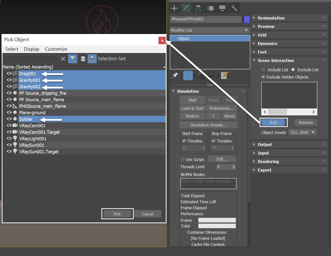
Now those nodes are in the Exclusion List, preventing undesired interactions with our simulation.

Select the Simulator → Output rollout and enable the output of Temperature, Smoke, Velocity and Fuel Grid Channel.
If you'd like to perform a Resimulation using Wavelet Turbulence for increasing the simulation detail, enable the Wavelet Grid Channel output.
Any channel that you intend to use after the simulation is complete, needs to be cached to disk. For example:
- Velocity is required at render time for Motion Blur;
- Temperature is usually used at render time to generate Fire;
- Wavelet is used for Wavelet turbulence when performing a Resimulation.
In this tutorial, we don't run Resimulation, nor render with Motion Blur option enabled. However, we keep the Velocity Grid Channel just in case.

List of Fire/Smoke Sources and Their Settings
We are going to create two different Fire/Smoke Sources. As an overview, we list them here first.
The main_flame emits fuel and burns. The dripping_fire emits small fire coming out of the main flame.
Let's create the sources.
Fire/Smoke Source | Emit Mode | Inject Power | Temperature | Fuel | Motion Velocity | Time Base | Prt Size |
|---|---|---|---|---|---|---|---|
PHXSource_main_flame | Volume Inject | Animated | 2200 | 1.0 | 1.5 | Particle Age | 0.2 |
PHXSource_dripping_fire | Volume Inject | 15 | 3000 | off | 1.0 | Particle Age | 0.1 |
Adding Main Flame Fire/Smoke Sources
Create a Phoenix Fire/Smoke Source in the scene: Modify Panel → Create → Helpers → PhoenixFD → PHXSource. Rename it to PHXSource_main_flame.
Press the Add button to choose which geometry to emit and select the PF Source_main_flame entry in the Scene Explorer.
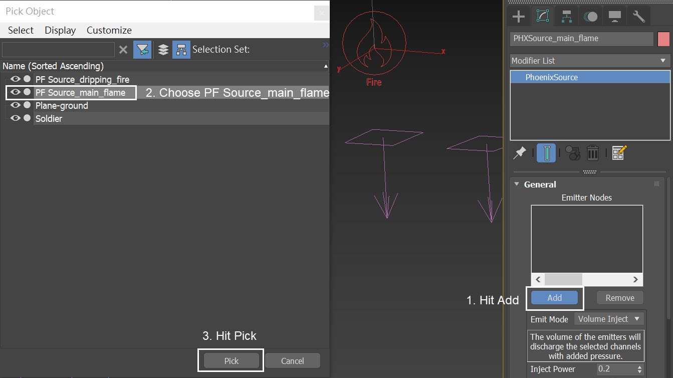
When you pick the PF Source_main_flame node, the Available Events dialog pops out. Choose both the PF Source_main_flame→PF Source_main_flame and PF Source_main_flame→Event 001.

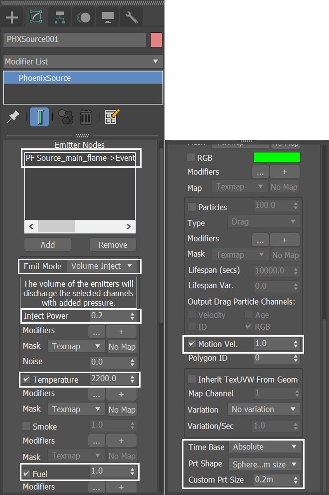
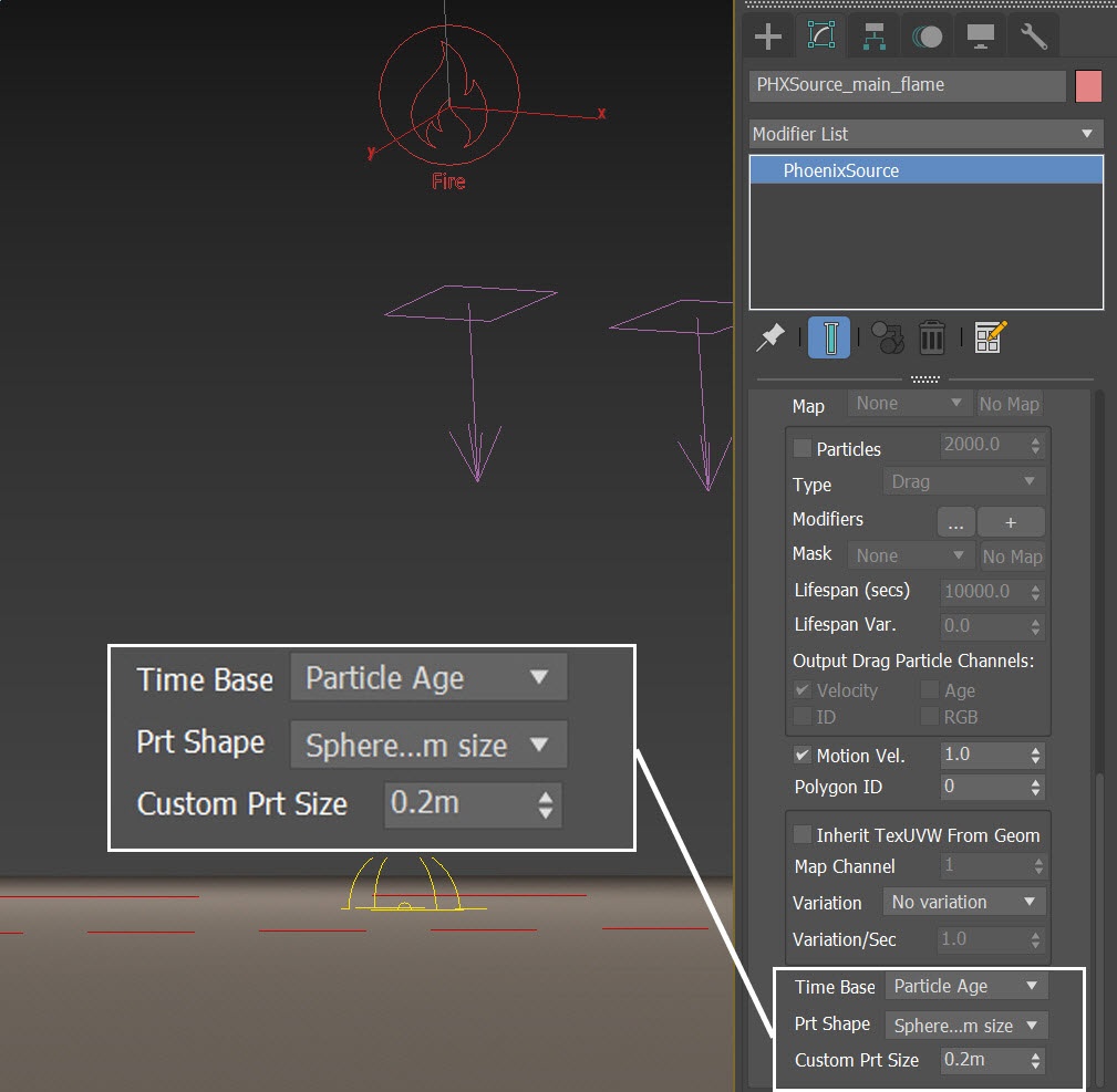
For the PHXSource_main_flame:
Set the Emit Mode to Volume Inject and set its value to 0.2;
Set the Temperature to 2200;
Disable the Smoke;
Enable the Fuel;
Motion Vel. to 1.0;
Prt Shape to Sphere, custom;
Custom Prt Size to 0.2 m.
Leave the Time Base to its default value (Absolute), we'll change that later.
Fuel Burning
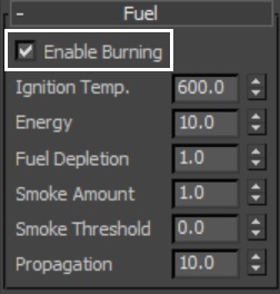
To allow Phoenix to burn the fuel from PHXSource_main_flame, select the Simulator and go to the Fuel rollout. Check the Enable Burning option and leave all settings at their defaults for now.
If you want your fluid to emit less smoke in zone 1, you can increase the Smoke Threshold amount here. If you want the flame to swell less, you can decrease the Propagation value. All of these parameters affect the character of the flamethrower. We'll tweak them a bit later.
Select the Phoenix Simulator → Simulation rollout → press the Start button to simulate.

Here is a Preview Animation of the simulation up to this step.
At this moment the fire is too hot, showing no details in the shader. Also, the flame is floating up too fast.
To enable the GPU Preview as seen in the video, select the Simulator → Preview rollout → GPU Preview → Enable in Viewport.
Gravity and Cooling
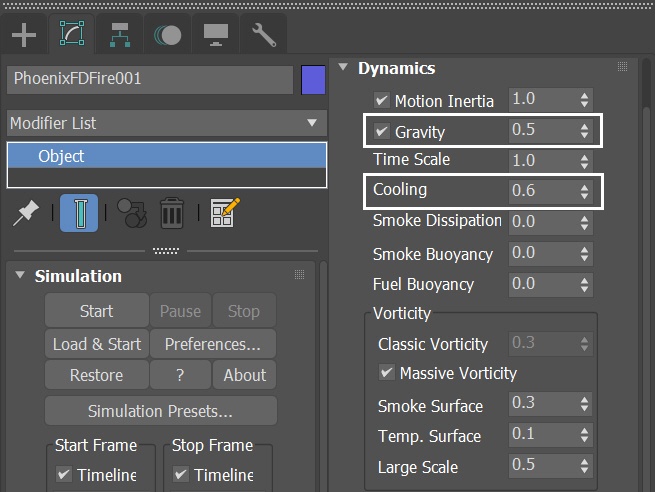
Select the Phoenix Fire/Smoke Simulator, go to Dynamics rollout. Decrease the Gravity to 0.5. Increase the Cooling to 0.6.
With the new dynamics settings, run the simulation again.
Now we can start to see a variance of shades in the flame as the fire cools down at the far side. And the flame doesn't go up that fast. However, the overall shape of the flame and its motion are too rigid.
Animate the Inject Power
Go to Graph Editors/Track View → Curve Editor and set keys to the curve of PHXSource_main_flame's Inject Power. We set keyframes to Inject Power, so it can change over time. Each frame and value are shown in the screenshots. All keyframes are set to Tangents to Linear.

With the PHXSource_main_flame selected, change its Time Base to Particle Age. Run the simulation again.
If you didn't set the Time Base to Particle Age, the animation of PHXSource_main_flame's Inject Power won't work correctly. If you leave it at its default (Time Base - Absolute), the source will not consider the animated value of the Inject Power base on particle's age.
Let's check the simulation after this step. Now the flame's motion and shape became more organic and natural.
The smoke does not seem thick enough, though. Let's adjust the smoke's opacity in the volumetric settings.
Adjusting Smoke Opacity
Select the Phoenix Simulator → Rendering rollout and press the Volumetric Options button.
Set the Fire Multiplier to 50.
Set the Smoke Opacity to be based on Smoke and then adjust the curve as in the screenshot.
We keep our Smoke Color at its default value (RGB = 51, 51, 51). However, we will change it later in the steps.

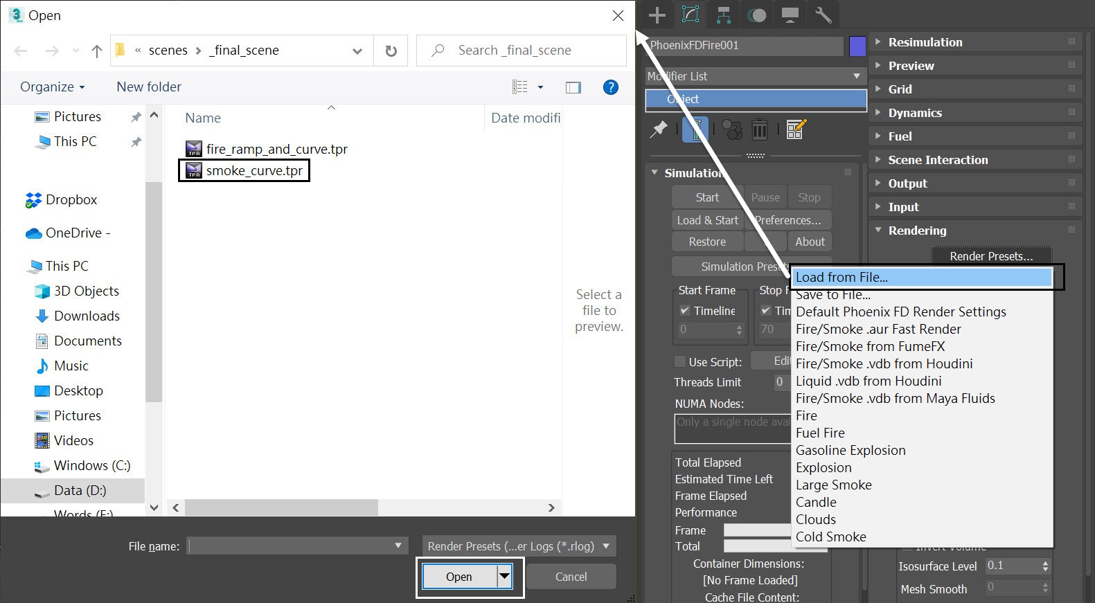
Instead of manually creating the smoke curve yourself, you can load the render preset file from the provided example scene files here.
Note that this action replaces all your rendering and preview settings.
Go to Rendering Rollout → Render Presets → Load from file and open up the smoke_curve.tpr file.
Let's see the result. Now the smoke appears thicker. Overall the appearance of the fluid has become more contrasty.
Adjusting Fuel Burning
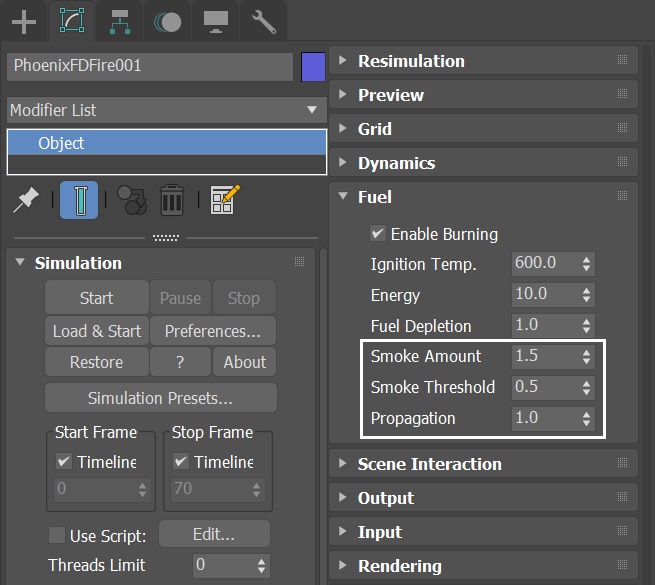
We want our flame to generate no smoke at zone 1 as we previously explained in the Anatomy of the Flamethrower section. So, increase the Smoke Threshold in the Simulator's Fuel rollout to 0.5.
Increase the Smoke Amount to 1.5, so we get thicker smoke.
Reduce the Propagation to 1.0, so we get a slimmer flame instead of a big chunky one.
With those new settings, run the simulation again.
The Smoke Threshold controls how much of the burning fuel produces smoke. Higher values cause less of the burning fuel to produce smoke.
The Propagation controls the speed of expansion of the fire and smoke generated by the burning fuel.
Let's preview the simulation. As you can see, now we get distinctive characteristics in different zones of the flame.
Increase Motion Velocity
To project the flame further, select the PHXSource_main_flame and increase the Motion Vel. to 1.5.
Run the simulation again.

The flame projects a bit further.
When the PHXSource_main_flame's Motion Vel. is set to 1.5, the simulated flame spreads roughly around 25 meters forward. This distance matches a flamethrower in real life. However, you can adjust this parameter based on your desire.
Adjusting Fuel Buoyancy
A real flamethrower is a weapon that ejects liquid fuel and flames in the air. The liquid fuel should fall because of gravity. Select the Phoenix Fire/Smoke Simulator in the scene, in the Dynamics rollout, set the Fuel Buoyancy to -10.
Run the simulation again.

Now the flame is constantly moving downward, while keep floating upward when burning. Though the effect is subtle, it does add up extra realism to the flame motion.
Our flame's morphology is taking shape. To improve the fluid simulation, let's switch the conservation method to PCG Symmetric in the next step.
PCG Solver
Select the Simulator and change the Conservation Method to PCG Symmetric, with a Quality of 100. Set the Steps Per Frame to 2.
The PCG Symmetric option is the best method to use for smoke or explosions in general, preserving both detail and symmetry. The high Conservation Quality allows the smoke to swirl better. For in-depth information, check the Conservation documentation.
With the new conservation method, run the simulation again.

We see that the fluid simulation's movement is more realistic now.
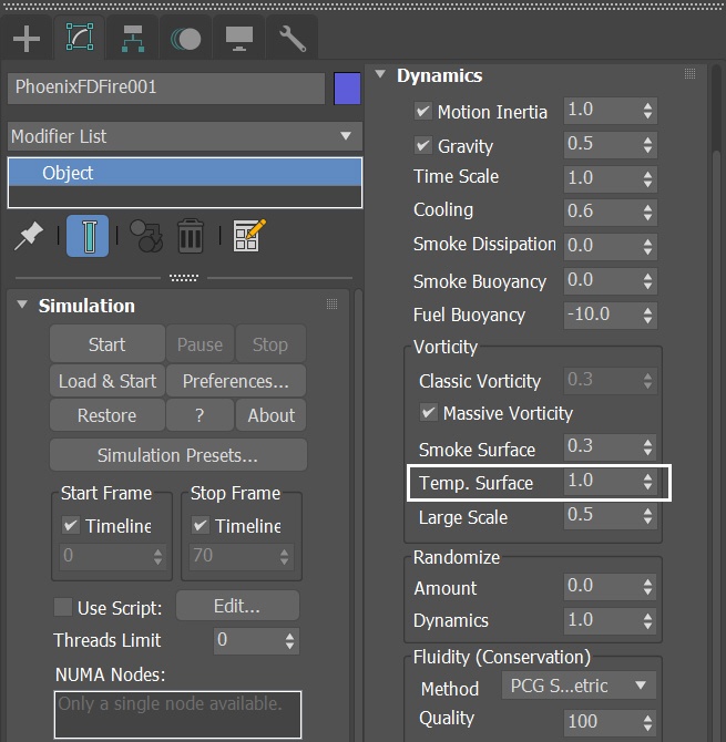
Adjusting Vorticity
To enhance the fire tongues, select the Phoenix Simulator and increase the Temp.Surface to 1.0 in the Vorticity section.
Run the simulation again.
Now we see distinctive fire tongues emerging from the flame.
To introduce more randomness in the smoke let's add Phoenix Turbulence in the next step.
Adding Phoenix Turbulence for Smoke Swirls
Create Helpers → PhoenixFD → PHXTurbulence.
Position to XYZ: [ 27.0, -2.5, 10.0 ].
Set the Strength to 2.0 and the Size to 3.0m.
Reduce the Fractal Depth to 3.
The Turbulence is used to bring more swirls in the smoke. You can use the Preview rollout's Force preview in order to see what velocities the Turbulence adds to the simulation. Note that you have to turn off the GPU preview in order to see the Force preview.
Then go to the Fire/Smoke Simulator and run the simulation again.

With the Turbulence force in the scene, we get more billowing smoke. At this stage, we are done with the simulation of the main flame.
Let's continue adding more components to the flamethrower.
Adding Dripping Fire Fire/Smoke Sources
Create a Phoenix Fire/Smoke Source in the scene: Modify Panel → Create → Helpers → PhoenixFD → PHXSource. Rename it to PHXSource_dripping_fire.
Press the Add button to choose which geometry to emit and select the PF Source_dripping_fire entry in the Scene Explorer.

When you pick the PF Source_dripping_fire node, the Available Events dialog pops out. Choose the PF Source_dripping_fire→Event 003.

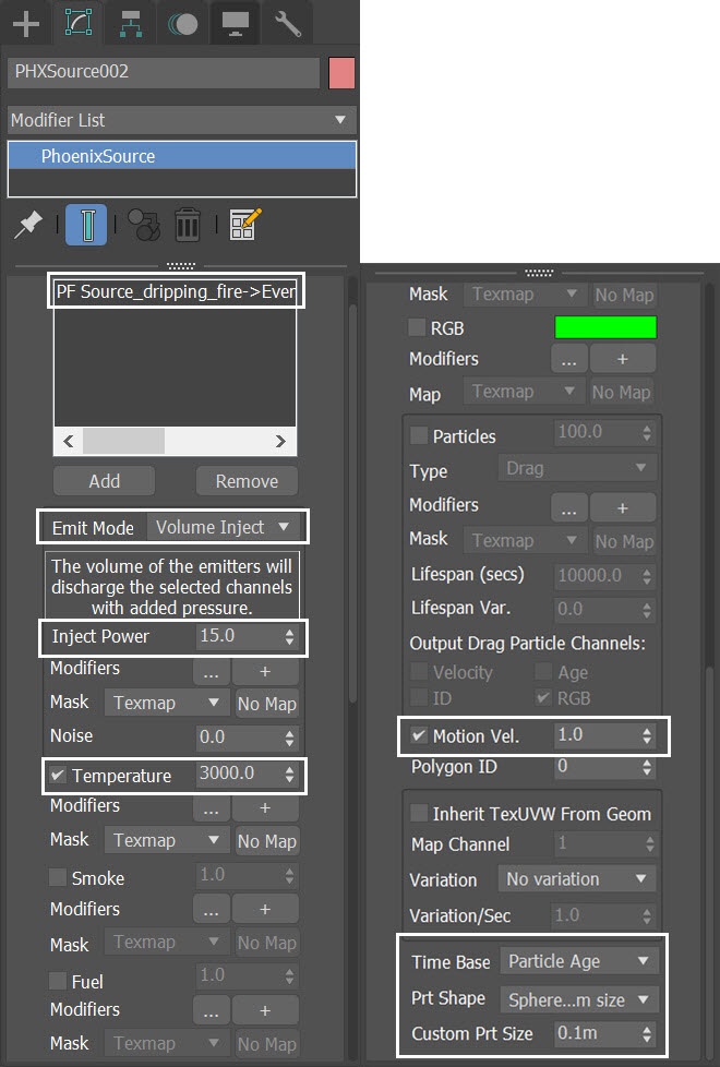
For PHXSource_dripping_fire:
Set the Emit Mode to Volume Inject and Inject Power to 15.0;
Disable the Smoke;
Set Temperature to 3000;
Motion Vel. to 1.0;
Set Time Base to Particle Age;
Prt Shape to Sphere, custom;
Custom Prt Size to 0.1m.
We increase the temperature of the dripping_fire source to 3000 Kelvins because we don't enable fuel for this fire/smoke source. The main_flame's temperature reaches around 3000 Kelvins once its fuel gets burned. To match the final color and brightness of the fire shading, dripping_fire's temperature is set to higher than the main_flame's temperature, which is 2200 Kelvins.
Final Simulation
In order to get a more detailed result we also increase the Grid Resolution by lowering the Cell Size for the final simulation.
Open the Grid rollout and set the following values:
- Cell Size: 0.056 m;
- Size XYZ: [ 223, 145, 73 ].
Press the Start button to run the final simulation.

Here we preview the final simulation.
Improving Volumetric Shading
Let's run a test render for frame 53. This helps us assess how to improve the overall render look of the simulation.
We choose frame 53 because it is representative of the whole animation. At frame 53, you can see clearly all the distinct characteristics of the flamethrower and the dripping flame. But you can choose other frames for test rendering as you like.
As you can see, the results are too bright, everything is washout and we can't see any detail.

Select the Simulator, and go to the Volumetric Render Settings. Adjust the gradient and curve of the Fire as shown.
Make the Smoke Color a little brighter than the default value. Set the Constant Color to RGB (90, 90, 90).
The color gradient is set to black-red-orange representing fire color at different temperatures, from coolest to hottest.
Note that the green region shows the temperature data range for the current timeline frame. When you scrub the timeline, this area changes as the grid content changes. In this case we have fire temperatures ranging from 0 to around 2500 Kelvins. When you set the color ramp and curve, make sure they are within the range of the green area because this is the data that will actually be rendered for this frame.
We use an S-shaped curve. Why set it like this? From left to the right, the curve begins with the low temperature values, then goes down at the highest temperature. By doing so, we can make sure we retain most of the details at a higher temperature, avoiding color washout.

Instead of manually creating the fire curve yourself, you can load the render preset file from the provided example scene files here.
Note that this action replaces all your render and preview settings!
Go to Rendering Rollout → Render Presets → Load from file and open up the fire_ramp_and_curve.tpr file.

With the new fire color ramp and curve, run a test render again. Now we see more details in the volumetric shading. And the whole image is sharp.
However, the smoke scattering and fire lighting are not convincing.
Select the Simulator, and go to the Volumetric Render Settings. Lower both the Light Power on Self and Light Power on Scene to 0.75. Also, decrease both the Own Light Scatter Mult and External Scatter Mult to 0.75.
You can see the effect of External Scatter Mult in the viewport when using GPU preview.

With the new volumetric settings, run a test render again. Now the volumetric effect appears more solid and convincing.
To make the shot more cinematic, in the next step, we are going to color correct the image using the V-Ray Frame Buffer.

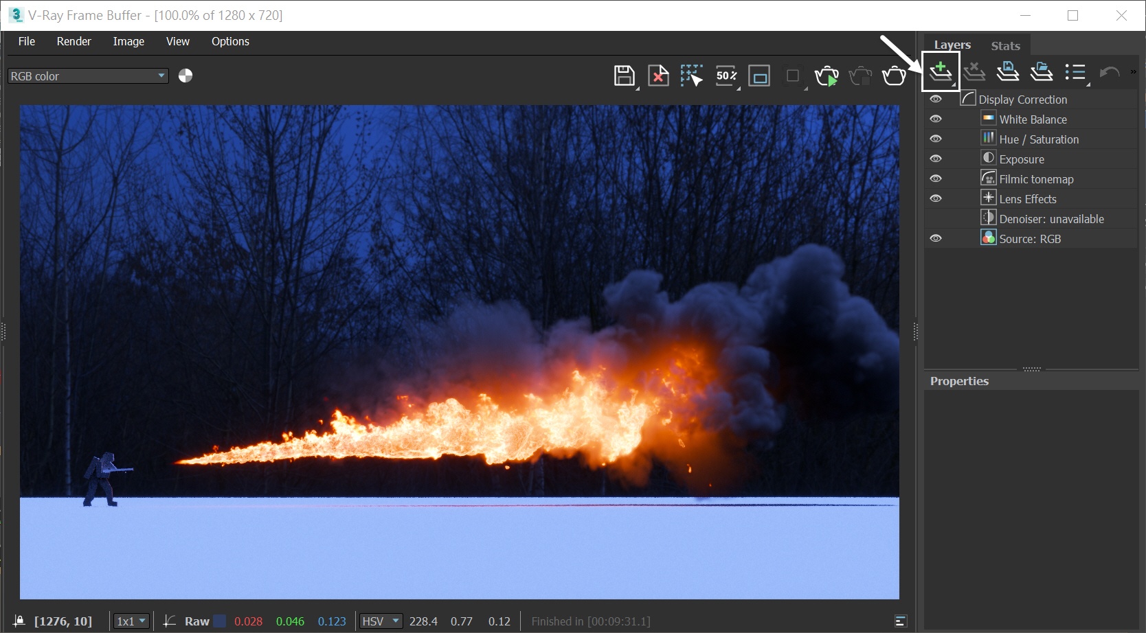
V-Ray Frame Buffer
Start the V-Ray Frame Buffer and use the Create Layer icon to add layers for Hue / Saturation, Exposure, and Filmic tonemap.
Using V-Ray 5 as our render engine we can take advantage of its Filmic Tonemap in the new VFB. However, if you are using an older version of V-Ray, you can get a similar effect by using a proper LUT in the VFB.
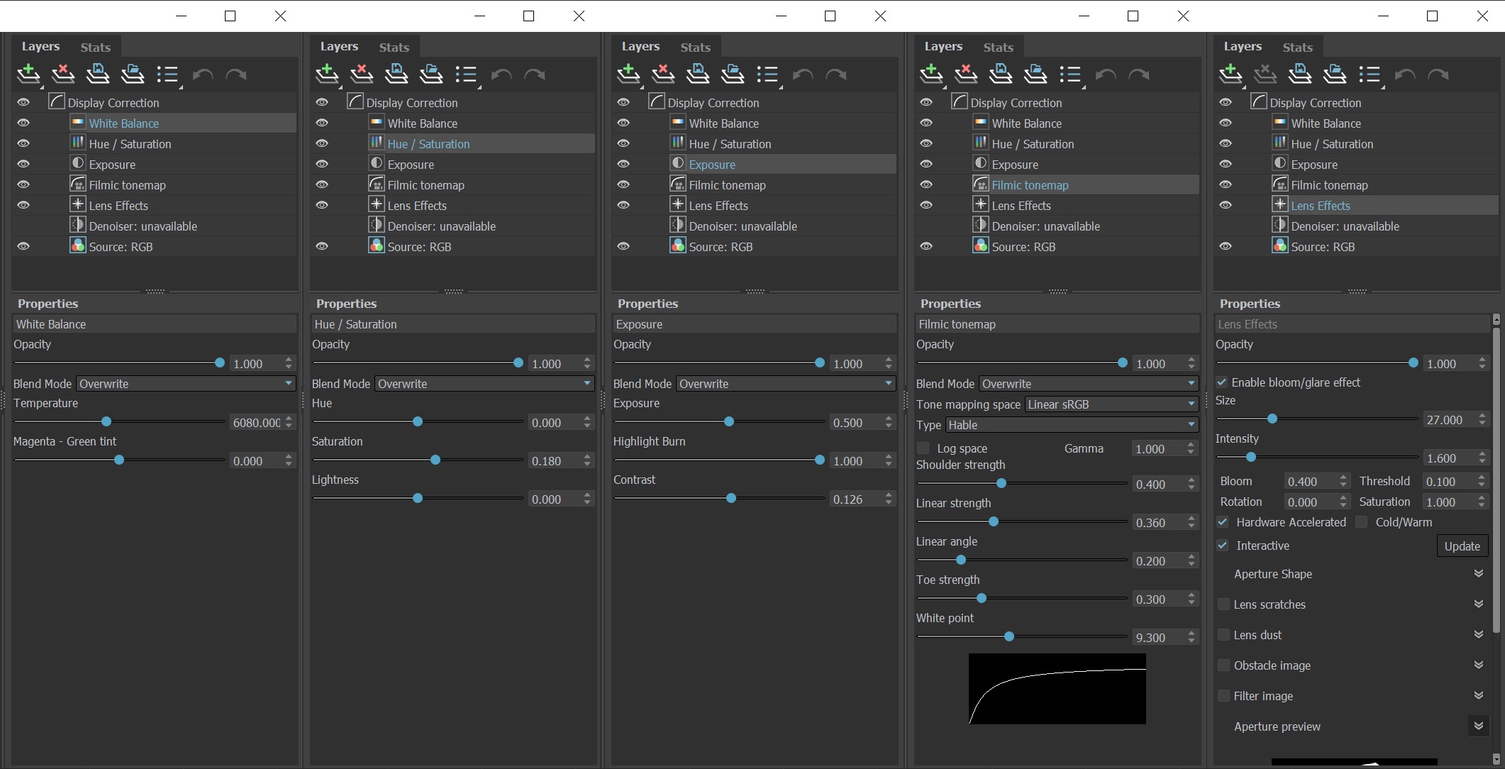
The final image is rendered using the V-Ray Frame Buffer with the color corrections and post effects set to:
White Balance
- Temperature: 6080.0.
Hue / Saturation
- Saturation: 0.18.
Exposure:
- Exposure: 0.5;
- Highlight Burn: 1.0;
- Contrast: 0.126.
Filmic Tonemap
- Type - Hable;
- Shoulder strength: 0.4;
- Linear strength: 0.36;
- Linear angle: 0.2;
- Toe strength: 0.3;
- White point: 9.3.
Lens Effects
- Size: 27.0;
- Intensity:1.6;
- Bloom: 0.4;
- Threshold 0.1.
The Filmic tonemap allows you to simulate film response to light with VFB.
Feel free to use other values for those post effects depending on your preferences.
And here is the final rendered result.
There are several parameters affecting the rendering speed of Phoenix volumetric data. You can find some useful tips for rendering optimization in this article: Volumetric Rendering In-Depth.