This page offers a guide on creating a waterfall simulation with Chaos Phoenix in 3ds Max.
Overview
This is an Advanced Level tutorial. The workflow for setting up the shot, and the Phoenix settings involved in the simulation are explained in detail. However, it's recommended that you have at least a basic knowledge of lighting and materials in 3ds Max.
To follow the steps of this tutorial, the minimum requirements are Phoenix 5.01.02 Nightly, Build from 5th of December 2022 and V-Ray 6 Official Release for 3ds Max 2018 at least. You can download nightlies from https://nightlies.chaos.com and get the latest official V-Ray from https://download.chaos.com. If you notice a major difference between the results shown here and the behavior of your setup, please reach us using the Support Form.
The instructions on this page guide you through the process of using Phoenix to create a grand magnificent waterfall. If you want to create a small waterfall, you can use the Waterfall quick preset from the Phoenix toolbar as a starting point.
To download project files: Download Project Files
Want to follow along but don’t have a license?: Download Free Trial
Units Setup
Scale is crucial for the behavior of any simulation. The real-world size of the Simulator in units is important for the simulation dynamics.
Large-scale simulations appear to move slower, while mid-to-small scale simulations have lots of vigorous movements.
When you create your Simulator, check the Grid rollout where the real-world sizes of the Simulator are shown. If the size of the Simulator in the scene cannot be changed, you can trick the solver into working as if the scale is larger or smaller by changing the Scene Scale option in the Grid rollout.
The Phoenix solver is not affected by how you choose to view the Display Unit Scale — it is just a matter of convenience. Setting the units to Meters is a reasonable choice for this setup.
Go to Customize → Units Setup and set Display Unit Scale to Metric Meters. Also, set the System Units so that 1 Unit equals 1 Meter.

Scene Layout
Here is the final scene layout. It consists of the following elements:
- A Phoenix Liquid Simulator.
- Scene geometry: Cliff_Terrain and Rock01~12.
- A Phoenix Liquid Source emitting from Plane_Emitter.
- Three Particle Shaders for the Foam, Splash and Mist particles respectively.
- PHXTurbulence Force to disturb the Mist particles.
- A Particle Tuner is used for limiting the affected region of the Plain Force.
- A Phoenix Plain Force as a wind force pushing the liquid more toward the cliff.
- Cliff_terrain geometry for the terrain. It is roughly 125 meters in height.
- A Box_pool geometry with its Phoenix properties set to Initial fill, for the pool at the bottom of the waterfall.
- A Box_particletuner geometry that is used in the Particle Tuner as Distance to condition.
The large rocks not only make the shot look more realistic, but also allow the stream to generate splashes when hitting them, that enhances realism.

For the Plane_Emitter, let's add a Shell modifier to it. And set one side of faces to ID = 2. Then we rotate it 160.0 degrees on the X axis, so the emitted fluid stream points toward the terrain.
There are two benefits of rotation of the Plane_Emitter like so. While keeping the same output amount of the fluid, we can (1) have less Z size of the simulator, (2) slow down the velocity of the water stream.

The final scene consists of the following elements:
- V-Ray Light Dome for lighting;
- A V-Ray Physical camera.

Scene Setup
Set the Animation Length parameter appearing in the Time Configuration window to 230, so that the Time Slider goes from 0 to 230.
The animation length is 230 frames, but we render from frame 140 to frame 230 only, a total of 3 seconds.

This tutorial consists of many steps to follow. To keep it concise, let's focus only on the Phoenix related steps and feel free to use the camera and light settings in the provided sample scene.
For your reference, below you can find the light and camera settings.
Camera Setting for VRayCam
Add a V-Ray camera from VRayPhysicalCamera from Create Panel > Cameras > V-Ray. The exact position of the Camera is XYZ: [-135.0, -338.0, 196.0 ].
The exact position of the Camera Target is XYZ: [-12.0, -114.0, 90.0 ].
From Aperture, the Film speed parameter is set to 20.0. F-Number is set to 12.0. Shutter Speed is set to 15.0.
In the Sensor & Lens rollout: Film gate is set to 36.0mm. Focal length is set to 40.0mm.
From Color & Exposure, set the White Balance option to D65.
Enable Motion blur.

Lighting
Press on the Cosmos icon in the V-Ray toolbar. In the HDRIs section → Day, choose Day 021. Press the green arrow to Import the HDR map. Chaos Cosmos generates a VRayLight in the scene with the HDR map plugged in the Texture slot.
The exact position of the V-Ray Light is XYZ: [108.0, -165.0, 0.0].
Set the VRayBitmap map's Horiz. rotation parameter to 330.0.
The Dome light's orientation is carefully tweaked so you will have a beautiful backlighting for the waterfall.

Anatomy of the Waterfall
The image here is the final render in this tutorial. The river falls from a 125-meter cliff to form a waterfall. Rocks in the river splash water. At the bottom of the waterfall there is a pool where misty air rises. Gradually more and more splashes and mist accumulate at the bottom.
Let's go through the steps and see how to build these features.

Phoenix Simulation
Let's start by creating a Liquid Simulator. Go to Create Panel → Create → Geometry → PhoenixFD → PhoenixFDLiquid.
The exact position of the Simulator in the scene is XYZ: [ 76.0, -14.2, 7.8 ].
From the object color swatch, change the color to turquoise. We give the simulator mesh a turquoise color instead of blue, to make it distinguishable from the splash particles (which are in blue by default).
Open the Grid rollout and set the following values:
- Scene Scale to 1.0
- Cell Size to 0.4 meters
- Size XYZ: [ 348, 556, 323 ] - the Simulator size is covering half of the terrain
- Container Walls - set both X, and Y to Jammed Both; set Z to Jammed (-)
During the RnD phase, we only cover half of the terrain with the Simulator for faster iterations. Setups such as this one where the simulation would behave similarly along the simulator width allow us to iterate only over a slice of the simulation grid and be confident that when we make the simulator wider, the simulation will retain its characteristics and will not change drastically.
We jammed the container walls for X and Y because in a later step we create a pool at the bottom. It leaks if the walls are open. In real production environment, if you have a terrain that has walls to hold the water pond, you can set the X and Y walls to Open.

Open the Output rollout and make sure you have the Liquid's Particle Velocity, Grid Liquid, and Grid Velocity enabled. Leave everything at its default.
The Particle ID is used during rendering to identify each particle. Use it when render time size variation is needed, if you would use the Particle Shader's Count Multiplier, or when frame blending will be involved. In this case since we are not going to do those operations, so to further reduce the output cache size, you can disable the Particle ID for the particles.
Any channel that you intend to use after the simulation is complete, needs to be cached to disk. For example, Velocity is required at render time for Motion Blur, so it needs to be cached to disk.

Add Liquid Source
Add a Liquid Source from Helpers → Phoenix FD → Liquid Source.
The Liquid Source is a Phoenix helper node. It determines which objects in the scene the Simulator emits from, how strong the emission is, etc.
Add the Plane_Emitter geometry to the Emitter Nodes list.

Once the emitter is added, set the Outgoing Velocity to 2.5 m.
Set the Emit Mode to Surface Force. This makes the object emit only from its surface area.
Set the Polygon ID to 2.
The Phoenix Source in 3ds Max can use Polygon IDs as a 'mask' - emission happens only from faces with a given ID.
In this scene, we set the Polygon ID parameter to 2. This forces the Liquid Source to emit only from the polygons with an ID of 2.
This way the liquid would only flow towards the cliff and would not spill sideways or upwards from the emitter.

At this stage, we don't need to simulate the full length of the animation. We only need a sample. Go to the Simulation rollout and set the Stop Frame to 180.
Press the Start button to simulate.

Go to the Preview rollout, and enable Show Mesh. Disable all other Voxel Preview channels, so they don't interfere.

Here is a preview animation of the simulation up to this step.
As you can see, the water is too slow. It has is simulated for 180 frames, but still has not reached the edge of the cliff. Let's increase the Time Scale for some frames, so the water can become waterfall in a shorter time range.
Animate Time Scale
With the Simulator selected, go to the Dynamics rollout and set key frames to the Time Scale.

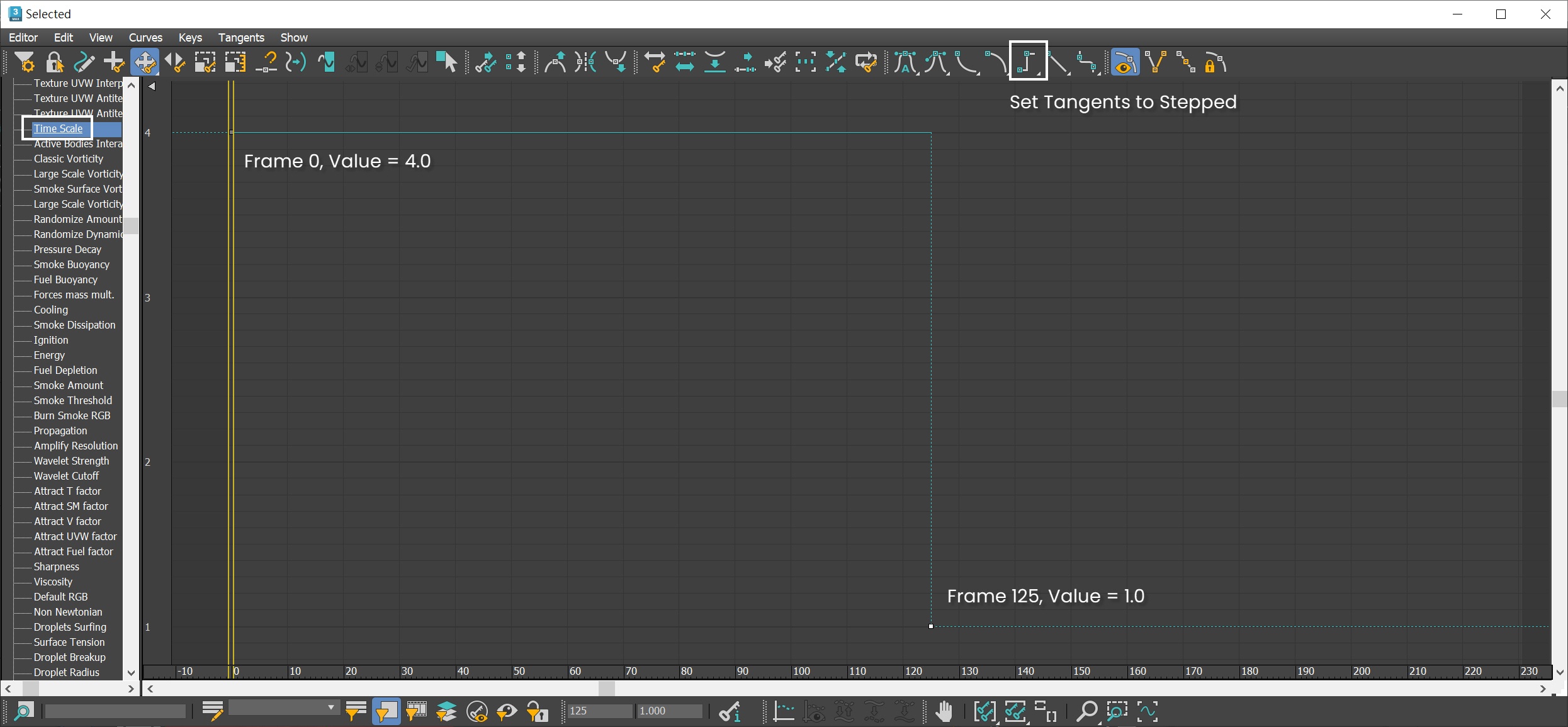
Go to Graph Editors/Track View > Curve Editor and set key frames to the curve of the Simulator's Time Scale. Setting keyframes to the Time Scale allows the water to run faster until frame 125. Each frame and value is shown in the screenshots. All keyframes are set to Tangents to Stepped.
Run the simulation again.
Here is a preview animation of the simulation so far.
Now we start to see a waterfall as the water flows down the cliff.
You can see the water hits the simulator's wall which is unrealistic. Don't worry, we can fix that by adding a Plain Force to push the water back toward the cliff.
From a side view, you can see the waterfall is away from the cliff terrain.

Adding Plain Force
To push the water back toward the cliff, we use a Phoenix Plain Force for the task.
Go to Create Panel > the Helpers tab > Phenix and add a Phoenix Plain Force in the scene.
The exact Position of the Plain Force in the scene is: XYZ[0.0, -130.5, 65.0]
Rotate the Plain Force to XYZ[-90.0, 0.0, 0.0].
Set its Strength to 4.0m
Set the Drag to 0.1
Set the Max Distance to 80.0 m.
Enable the Apply Force Behind Icon option
- In the Affect list, delete all other particle types and leave only Liquid
We set the Max distance to 80.0 meters as this is the distance from the Plain Force to the cliff. This way only the falling water is affected by the Plain Force, not the upstream water. You can adjust the value based on your custom terrain.
For a better simulation performance, we set the Plain Force to only affect the liquid particles. The other particles' motion is based on liquid particles, so it's fine not to include them in the list.

Here is a preview animation of the simulation.
From the side view, we can see that the water now keeps closer to the cliff.

Simulate Splash and Mist particles
With the liquid simulator selected, go to the Splash/Mist rollout.
Enable the Splash/Mist option. When asked if you'd like a Phoenix Particle Shader generated for the Splash particles, select Yes. This automatically sets up the link between the Splash particles group, the Particle Shader, and the Liquid Simulator.
Rename the new particle shader to ParticleShader-Splash.
Run the simulation again.

Change Preview Color
With the simulator selected, in the Preview rollout, enable Particle Preview.
To easily spot which particles are which, let's change the color swatches for the different particle types.
Disable the Liquid particle preview. Set the Splash, Mist, and Foam to Blue (RGB: 0, 0, 255), Red (RGB: 255, 0, 0), and Green (RGB: 0, 255, 0) color respectively.
The exact RGB color for the particle preview is not important - it's used only for the preview and not for the rendering. Choosing other colors as long as they are distinguishable is optional.

Now we start to see splash particles in the simulation. But too much liquid gets converted to splash/mist. We'd like both the Mist particles need to be less, and the Liquid particles to remain more numerous. See the FLIP Particles Life Cycle for more information on how liquid converts into splash and mist particles.
Splashes are the key visual component in a waterfall. We can have less Mist particles since they will be more transparent in our final render and we can increase their size to compensate for having less mist particles.
Here is how we know the Mist particles are too much:
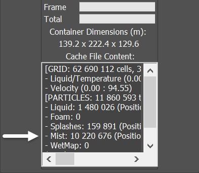
With the the simulator selected, under the Simulation rollout you can see the Cache File Content window.
Visible from the data, the Mist particles vastly outnumber the Splashes particles. In a waterfall simulation the Mist is less important than splashes, so we will reduce the mist particles number - they are taking away valuable simulation time now.
With the simulator selected, go to Splash/Mist rollout, decrease the Splash to Mist to 0.1. This way fewer splash particles are converted to mist. Decrease the Mist Amount to 0.05.
In the Properties section, reduce the Affect Liquid to 0.3. This reduces the amount of liquid particles being converted to splash/mist particles.
Run the simulation again.
You can keep more Mist by decreasing the Mist Amount to 1.0 or 0.10. Though this takes more simulation and rendering time for the mist particles. On the other hand, you can also increase the Mist particles at render time by increasing the Count multiplier in the Particle Shader later.

Here is a preview animation of the simulation up to this step. Now we have considerably less mist particles and retain of more liquid particles. Now the amount of Liquid, Splash, and Mist particles is now in good proportion.
The dynamics of the splash/mist look okay, but they need more drag for a great looking waterfall.
Simulate Air Effects
With the simulator selected, go to the Dynamics rollout. Enable the Simulate Air Effects option.
Run the simulation again.
Simulate Air Effects is an option that turns on the built-in air simulator for the areas in the simulation grid which are not full of liquid. The air velocity is affected by the liquid movement, by Sources, or by fast-moving obstacles inside the Simulator. In turn, the air velocity affects and carries splash, mist and foam particles. The air simulation can dramatically increase the quality of splash and mist effects.

Here is a preview animation of the simulation up to this step. With the Air Effects enabled, now the dynamics of falling splashes and mists look more convincing.
Increase Splash/Mist's Air Drag
To further enhance the heavy look of splash/mist falling, let's increase their Air Drag. With the simulator selected, in the Splash/Mist rollout - Properties set the Splash Air Drag to 2.0 and Mist Air Drag to 3.0.
With those new settings, run the simulation again.

Here is a preview animation of the simulation up to this step.
Adjust Splash Amount
To make the distribution of the Splash more distinct, let's increase the Threshold of the Splash/Mist to 20.0. To compensate the decreased number of splashes, increase the Splash Amount to 20.0.
A higher Threshold for the Splash helps forming a pattern in the splash particles, while avoiding smear of the particles.

Here is a preview animation of the simulation up to this step. Now the distribution of the splashes looks good.
Adjusting the splash birth By Free Fly
With the simulator selected, go to the Splash/Mist rollout. Increase the By Free Fly to 0.4.
By Free Fly controls how likely a free falling or flying liquid particle turns into splash. The main usage of values above 0.0 is in waterfall simulations.

Here is a preview animation of the simulation up to this step. We have more splashes generated when the liquid is in free fall.
Enable Foam
Select the Foam rollout of the Phoenix Liquid Simulator and enable it. A pop out window prompts us to create a Particle Shader for the foam, so select Yes.
Rename the new Particle Shader to ParticleShader-Foam.

With the simulator selected, go to the Foam rollout. Set the Half Life to 3.0. Decrease the Size to 0.075 m.
In the Foam on Hit section of the Splash/Mist rollout, set the Foam on Hit Amount to 1.0. Set Min. Age to 0.1.
Run the simulation again.
We decrease Foam's Half Life to 3.0 seconds so it has a shorter life and doesn't stay there for too long, while it is constantly generated through the help of the Foam on Hit option. You can change it to another value to your preference.
The Foam on Hit in the Splash/Mist rollout is the main contribution of Foam generation in this step, while the Foam Amount in the Foam rollout does not significantly affect the foam birth in this particular setup.
Min. Age is the Minimum age for foam production. Only splash particles with a particle age above this limit produce foam when they hit the liquid surface.
The Foam Size of 0.075 meters (7.5 centimeters) is carefully chosen so that in such camera distance we have a visible foam but we avoid a look that is too grainy. You can also adjust the apparent foam size in the Particle Shader by tweaking its Size Multiplier.

Now we start to see foam particles being generated in the scene, but they are shooting upward in an unrealistic way.
Improve Foam Dynamics
Let's focus on the Foam dynamics now.
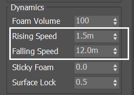
With the Simulator selected, go to the Foam rollout. In the Dynamics section, reduce the Rising Speed to 1.5m (this means that foam bubbles underwater travel upwards are 1.5 meters per seconds). Decrease the Falling Speed to 12.0m (this means that foam particles flying in the air fall at 12 meters per second).
Here's a preview animation of the simulation. Now the foam movement looks convincing.
Improve Foam Pattern Formation
With the Simulator selected, go to the Foam rollout. In the Patterns section, set the Formation Speed to 1.5 and Radius to 1.6m.
Formation Speed controls the rate of formation of foam patterns. In nature, these are caused by liquid flows rising to the surface and pushing the foam aside. For more information, check out the Formation Speed example.
Radius is the average foam radius in scene units of a single circular pattern core.
The value of 1.6 meters is chosen to look good in the scale of this particular setup - remember that the waterfall is 100 meters tall, so a smaller foam radius would make foam patterns hard to distinguish.

Here is a preview animation of the simulation up to this step.
The foam pattern formation is subtle from this camera view. You can set up another close-up camera to see it from the top.
Create a Pool
Go to Create Panel → Geometry → Standard Primitives → Box . Create a box in the scene. Rename the box to Box_Pool.
Set its Length, Width and Height to 103.0 m, and 294.0m and 6.3m respectively. Segs from all sides to 1.
The exact position of Box_Pool is XYZ: [0.77, -74.7, 8.24 ].
The box is just big enough to cover the bottom of the waterfall and to be used for forming a pool there by creating liquid particles right from the start of the simulation, so we don't have to wait for the liquid to fill up during regular simulation.

Since the Box_Pool only serves as initial fill liquid source, we don't have to render the geometry out. With the Box_pool selected, right-click → Object Properties. Enable the Display as Box option. Disable the Renderable checkbox.

With the Box_Pool selected, right-click and select Chaos Phoenix Properties.
Enable Initial Liquid Fill. This option fills the geometry with liquid at the very beginning of the simulation.
Run the simulation again.

Here's a preview animation. Now we can see a pool at the bottom of the waterfall, but the pool water gets pushed toward the cliff by the Plain force. Let's fix it in the next step.
Tuning the Plain Force with a Particle Tuner
Go to Create Panel →Geometry→Standard Primitives → Box. Create a box in the scene. Rename the box to Box_ParticleTuner.
Set its Length, Width and Height to 87.0 m, 296.0m and 95.0m respectively. Segs for all axes can be set to 1.
The exact position of Box_ParticleTuner is XYZ: [0.0, -82.5, 23.0].
This box is used for defining the region where Plain Force takes effect. We leave a gap for the pool, so that the Plain Force won't push the pool water toward the cliff.

Since the Box_ParticleTuner is only used for the Particle Tuner in a later step, we don't have to render the geometry out. With the Box_ParticleTuner selected, right-click → Object Properties. Enable the Display as Box option. Disable the Renderable checkbox.
With the Box_ParticleTuner selected, right-click and select Chaos Phoenix Properties.
Disable the Solid checkbox. This option will prevent the interaction of the box geometry with the liquid simulation.

Go to Create Panel → Helpers → PhoenixFD → ParticleTuner. Create a Particle Tuner anywhere in the scene.

With the Particle Tuner selected, click on the Edit Condition button to change the condition.
The Particle Tuner assesses all particles in the simulation and changes their values, if they pass a certain condition.
In this example we limit the Plain Force to only affect the designated region - that is inside of Box_ParticleTuner.
The conditions can be very simple, but you can also build more complex conditions with the Particle Tuner's Expression operators.

In the Edit Condition window, click on Age_phx, then the Edit Value Expression window shows up.

Switch the condition from Channel - Age to Distance To. Press the None button and choose the Box_ParticleTuner geometry in the scene.

Click on the Is Greater Than, so the Edit Compare Expression window shows on the right. Change the condition from Is Greater Than to Is Less Than.

Below the Is Less Than, change the value from 1.000 to 0.000. When a particle is inside the box geometry, the distance to the geometry will be a negative number, so this is why we set up the condition to "Is Less Than: 0.000".
Note that the unit for distance is in simulation grid voxels. If you change the Simulator's Grid Resolution, so does the actual distance to the particle affected by the Particle Tuner. In this particular case, we can just set the value to 0.000, so we don't have to worry when changing the grid resolution.

Now that we're done with the condition settings, close the Edit Condition window. With the Particle Tuner selected, disable the Then - Viscosity checkbox - we don't want to change any of the channels, we just want to limit the effect of the plain force. Then, set the Buildup Time to 0.0 so the Tuner acts instantly, without delay. In the Affect by Forces, add the PlainForce in the scene.
With those new settings, run the simulation again.
This way the condition that the Particle Tuner sets is the following: when particles go inside the region of Box_ParticleTuner, they are pushed by the PlainForce immediately.

Let's preview the animation.
Disturb the Mist with Phoenix Turbulence
To create a Phoenix Turbulence, go to the Create Panel → Helpers→ PhoenixFD and click on PHXTurbulence.
- Set its position to: XYZ[ 340.0, 80.0, -243.0]
- Set its Strength to 25.0
- Set its Size to 40.0m
- In the Affect list, delete other particles, leave only the Mist
Run the simulation again.
We only put Mist in the Affect list because we want to disturb solely the Mist particles. You can add other particles in the list if you prefer.

Let's preview the animation at this step.
Final Simulation
For the final simulation, let's move the simulator and increase its grid size so it covers a larger region.
The exact new position of the Simulator in the scene is XYZ: [ 0.0, -14.2, 7.8].
Open the Grid rollout and set the following values:
Cell Size: 0.4 m
Size XYZ: [ 731, 556, 323]
Run the final simulation.

Here is a preview animation of the final simulation.
Set up Particle Shader for Mist
We have a Particle Shader for splashes and foam already. For the Mist particles, we have to create a new Particle Shader manually.
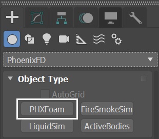
Go to Create Panel→ PhoenixFD and press the PHXFoam button to create a new Particle Shader in the scene. Rename it to ParticleShader-Mist.
Press the Add button and pick the Liquid Simulator, then select the Mist particle group. When doing so, a pop up window prompts you to add PhoenixFDLiquid in the Liquid Simulator slot of the shader, press Yes.
Set the ParticleShader-Mist mode to Fog.

Water Material
Let's take a look at the water material now.
Create a V-Ray Material and assign it to the PhoenixFDLiquid Simulator. Set the Diffuse color to black.
Reflect and Refract colors are set to white - it produces a completely transparent material if the Index of Refraction is set to 1 (which is the IOR of clear air). But let's set the IOR to 1.333, which is the physically accurate Index of Refraction of water.
Keep the Max depth to its default value of 8 for both Reflection and Refraction.
To slightly blur the specular highlights produced by the sources of illumination in the scene, reduce the Reflection Glossiness to 0.95.
If we render now, we'd notice that the water is completely transparent and looks a bit boring.
Instead, let's switch the Translucency to Volumetric. Set the Fog color to RGB : [233, 236, 239] and set the Depth to 100.0.
Set Scatter color to RGB : [44, 140, 119]. Set SSS amount to 0.5. This produces the type of shading expected in a large body of water containing all sorts of particles that interfere with the light rays.
Setting the Translucency to None saves some rendering time.

Run a test rendering. The splashes look too big. Let's fix the issue by adjusting the Particle Shader's settings in the next step.

Adjust the Particle Shaders
Let's make some adjustments to the Particle Shaders for Foam, Splash and Mist.
For the ParticleShader-Foam:
- Set Mode to Points
- Enable and set the Light Cache Speedup to 0.999
For the ParticleShader-Splash:
- Set Mode to Points
- Enable and set the Light Cache Speedup to 0.999
For the ParticleShader-Mist:
- Set Mode to Fog
- Set Fog Voxel Size to 2.0m
- Disable Volume Light Cache
- Increase Fog Density to 0.6
Volume Light Cache enables light caching, which can speed up bucket rendering considerably. But when enabling this option for the ParticleShader-Mist might cause GI flickering in the mist particles rich area.
- When using V-Ray progressive rendering, the Volume Light Cache option might slow down rendering startup or the overall render speed
- This option refers to the internal Phoenix Light Cache, which is unrelated to the V-Ray Light Cache
Feel free to adjust the settings for those Particle Shaders, in terms of Size Multiplier and Count Multiplier to fit your artistic taste. For example, you can increase the Count Multiplier of the Mist particle if you want more mist at the bottom of the waterfall.

Run a test rendering. Now we see the splashes are in appropriate size. Let's continue to the next step, adjust the Absorption Color of the Mist.

Mist Absorption Color
With the ParticleShader_Mist selected, go to Fog rollout. Change the Absorption Color to Blue (RGB: 60, 79, 124).
The Absorption Color can affect the opacity of the fog as well, depending on how bright or dark its color is. Brighter colors make the volume more transparent, while darker colors make it more opaque (denser).
In real world, absorption is strong in the red and weak in the blue for the water. Here we set the absorption color to blue for artistic purposes.

Run a test rendering. Now we have more interesting color contrast in the rendering. The absorption color gives mist particles subtle yellowish tint.

Mist Phase Function
To further increase realism to the shot, let's tweak the value for Phase Function of the Mist particle shader. With the ParticleShader_Mist selected, set the Scattering mode to Ray-traced. Increase the Phase Function to 0.7.
Phase Function controls the direction in which the light scatters inside the volume. Negative values correspond to backward scattering, which mimics a volume made up of solid particles and produce denser and more detailed looks. Negative values are more suitable for smoke or dust effects. Positive values correspond to forward scattering, which mimics a volume made up of water droplets where light scatters more. Positive values are suitable for highly scattering volumes such as clouds. The default value of 0 scatters the light in all directions and creates an even, diffuse look.
We set the Phase Function a positive value of 0.7 because the mist is made up of small water droplets and thus needs to forward-scatter. You can try other values to fit your needs.
Note that the Phase Function is ignored when Scattering is set to Approximate or Approximate+Shadows, and the parameter is grayed-out.

V-Ray Frame Buffer
Run a test rendering. Now you can see more back lighting in the mist rich area.
To further fine-tune the image, in the V-Ray Frame Buffer use the Create Layer icon to add layers for Exposure and Filimic tonemap.
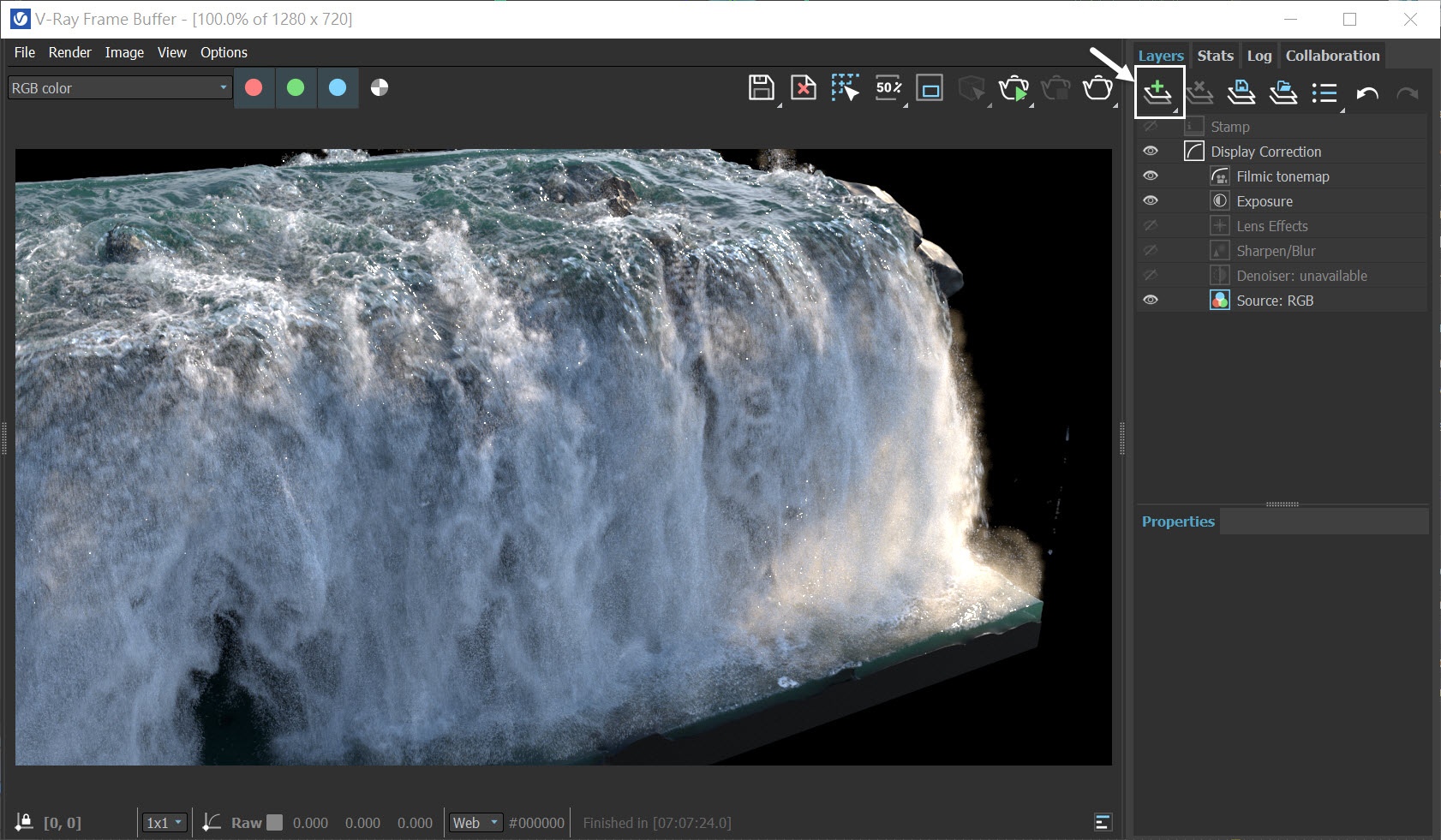
The final image is rendered using the V-Ray Frame Buffer with the color corrections and post effects set to:
Exposure:
Exposure: -0.4
Highlight Burn: 1.000
Contrast: 0.00
Filmic tonemap:
Blending - Overwrite: 0.200
Type - Hable
Shoulder strength: 0.330
Linear strength: 1.000
Linear angle: 0.400
Toe strength: 1.000
White point: 1.540
Feel free to use other values for the post effects depending on your preferences.

Alternatively, you can load a layer tree Preset from the Waterfall_VFB.vfbl file that is provided in the sample scene.

And here is the final rendered result (from frame 140 to frame 230).