This page contains chapter 1 of the Houdini to 3ds Max Alembic Workflow tutorial, covering the export of Poly Geometry.
Overview
The Houdini setup will not be discussed in detail. You can check the provided PROJECT_ROOT → Regular_Poly_Geo folder → vray_abc_export_sphereAnim_Chapter01.hip file for reference, which you can download from the button below.
The Chapter is divided into two subchapters:
- Partitioning the geometry
- Exporting Alembic Sequence for rendering with motion blur
You can download the projects file from here:
Partitioning the Geometry
Let's first take a look at partitioning the geometry in the Alembic File so different materials can be applied to different groups of faces. You can think of this as Material IDs or Face Sets.
By default, Houdini dumps all geometry fed to the ROP Alembic Output in a single shape (that is, the 'poly mesh' inside the Alembic file). If you have a tree and you want to assign different materials to the bark, branches and leaves, there would be no way to separate them.
The image to the right shows how the Alembic Hierarchy looks in the V-Ray Proxy UI when no steps are taken to partition the geometry. As you can see, there is a single object reference in the entire file, named after the last Houdini node before the ROP Alembic Output - OUT_sphere.
Instead of this, we would like to have separate object references for the sphere body, the connectors and the cables, so we can assign different materials to them.
Let's see how to do this.

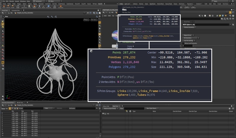
The image to the right shows how the example geometry looks like. It is a ball with a bunch of connectors for the cables going into it. You can open the provided .hip file to follow along.
We are using a File SOP to import this obj file but the same workflow holds for any polygonal geometry - both created inside Houdini and imported from outside.
The Sphere has 5 Primitive Groups - Links, Links_Frame, Links_Inside, Sphere and Tubes.
We would like to export the geometry such that those groups can be used for Material Assignment in 3ds Max (i.e., so they are listed as separate objects in the Proxy Mesh Visibility rollout of the V-Ray Proxy).
Houdini provides two ways to go about doing this:
- You can use the Houdini Groups to generate 3ds Max/ Maya Face Sets. This is done from the ROP Alembic Output → Geometry tab → Face Sets: Save Non-Empty Groups as Face Sets. As the parameter name implies, this generates a Face Set for each non-empty group of the input geometry.
- You can use a String Primitive Attribute to partition the geometry into separate Shapes. You can do this from the ROP Alembic Output → Hierarchy tab → Partition Mode: Use Attribute Value. This generates a separate Shape in the Alembic file based on a user-specified String attribute (such as s@name).

Let's see how to generate a string @name primitive attribute based on the groups, so we can partition the alembic file into separate shapes.
We use a Name SOP to generate a @name Primitive attribute based on the groups that came with the obj file. Note that the Number of Namings is 3. We create 3 separate values for the name attribute - links, sphere and tubes. We expect those to come as separate objects once the Alembic file is imported through the Proxy Import in 3ds Max.
You could do the exact same thing to partition packed geometry, agents, etc. As long as you have a clear idea of what your needs are, you can always drop a Wrangle node to create a custom string attribute and feed it to the Alembic Output ROP's Partition Attribute parameter.

All you need to do now is drop a ROP Alembic Output node and set the output Alembic File path.
Then, at the bottom of the Hierarchy tab, set the Partition Mode to Use Attribute Value and type name in the input field for the Partition Attribute parameter.
Press Render to Disk to save the file.

In 3ds Max, go to Create → Geometry → VRay → VRayProxy.
Load the exported Alembic file and open the Proxy Mesh Visibility rollout.
If everything was set up correctly, you should be able to see a separate entry for each unique value of the @name attribute - links, sphere and tubes in this case.
The strings in the Object Name List correspond to the IDs in the Object ID List, and those IDs can be used with the Multi/ Sub-Object Material to assign different shaders to each of those shapes, or the V-Ray Multi Sub Tex to assign different textures, if the shapes share the same material.

Create a Multi/ Sub-Object Material and assign three V-Ray Materials to the first 3 input slots. As mentioned above, Index 1 is the links (red), Index 2 refers to the sphere (green) and Index 3 - the cables (blue).

Motion Blur
If the geometry is animated and you plan to render with motion blur enabled, you have two possible routes:
- Export the sequence as a single Alembic file
- Export each frame as a separate Alembic file
With the first option, no additional setup is required on your part but you should keep in mind that V-Ray ignores the v attribute. The motion blur is derived from the transform/deform information stored in the Alembic file.
Drop a ROP Alembic Output and set the Frame Range according to your needs.
Make sure to set the Partition Mode as well.
This setup exports a single Alembic file for the entire Start/End range.
Note that an Attribute Delete SOP is placed right before the ROP Alembic Output. The AttribDelete is used to remove the @v attribute.
This won't be necessary in your setup – the sole purpose of this node is to stress that with this setup @v is not needed and not used by V-Ray.

Import the Alembic file through Create → Geometry → VRay → VRayProxy.
To render the geometry with motion blur, you can create a V-Ray Physical Camera and select Enable motion blur under the Physical Camera → Shutter section of the parameters.
V-Ray uses the transform/deform information stored in the Alembic file to determine the motion blur direction.The magnitude (strength) of the motion blur effect can be tweaked from the Shutter speed parameter under the Aperture rollout.

A Multi/Sub-Object Material is assigned to the V-Ray Proxy. The IDs of the Sub-Object material correspond to the IDs on the VRayProxy → Proxy Mesh Visibility rollout.
A (Metallic: 1.0 , Reflection: white) V-Ray Material is assigned to indices 1 and 2, which map to the links and sphere groups.
A V-Ray Light material is assigned to index 3 – the tubes.
A Vertex Color texture is piped into the Light Color parameter of the Light Material, reading the point @Cd attribute stored on the tubes.

As seen in the image, the motion blur correctly follows the deformations of the sphere even though no velocity information is present in the Alembic file.
 Frame 8 - motion blur is present even though no velocity information is provided to the Alembic file.
To export the animation as separate Alembic files, all you need to do is add a $F in the naming of your sequence, so Houdini knows to separate the files.
In this example, the output file is named sphereAnim.$F4.abc, with the Frame Range set to 1-48.
Note that the Attribute Delete SOP is still present – the Alembic file contains no velocity information.
Our expectation is to have no motion blur once we load it into the V-Ray Proxy. V-Ray can't calculate motion blur when the sequence is made up of separate Alembic files.

To load the sequence of Alembic files, you need to provide the V-Ray Proxy with a hint in the Mesh file path.
Because we exported the alembic sequence as fileName.$F4.abc, we need to give the Mesh file path the same pattern - fileName.####.abc, where each # symbol stands for one leading digit.
The rest of the 3ds Max setup is exactly the same.

When you start the render, no motion blur is present.
When loading an Alembic file sequence, V-Ray needs the velocity attribute.
 Frame 8 of the sequence of Alembic files - there is no motion blur because @v is not present.
The easiest way to generate the velocity information in Houdini would be to use a Trail SOP in Compute Velocity mode.
Note that there are three Velocity Approximation modes on the Trail SOP – Forward, Central and Backward Difference.
Forward Difference is what you should use when trying to match the V-Ray generated motion blur (default is Backward Difference)).

Here is the rendered image in 3ds Max with @v created using the Trail SOP and the Approximation set to Forward Difference.
 Frame 8 - @v computed with Trail SOP set to Compute Velocity :: Forward Difference