This page provides information about the Input tab of the V-Ray Volumetric Grid.
Overview
The Input rollout determines the path of the input files for rendering and preview as well as the playback effects. Note that some playback settings require a fractional input frame, in which case the frame is blended between the previous and the next one.
Field3D files which come from FumeFX must be exported with gzip compression! If they are exported with the default proprietary FumeFX compression, they will not be imported properly in V-Ray Volume Grid.
Parameters
Use the referenced scene name | inPathReferenced – When enabled and calculating the path for a referenced container, the original referenced scene name is used instead of this scene name.
Cached Frames – Shows information about the cached frame range.
Preview and Render Path | inPath, inPathResolved – Gives the directory and the name template for the input files.
Click the "..." button to open a menu with the following options:
Browse – Opens a dialog for choosing one of several cache file types. The V-Ray Volume Grid can import the following cache files: Phoenix FD *.aur, Field3D *.f3d and OpenVDB *.vdb.
Help – Opens the Help page for the Input tab of the V-Ray Volumetric Grid.
You can suppress showing of the dialogues offering presets using the inDontOfferPresets attribute of the Volume Grid. E.g. "setAttr VRayVolumeGrid1.inDontOfferPresets 1".

Time Bend Controls
This section contains playback options you can use for retiming a cached sequence. Using these, you can speed up, slow down or animate the motion of the sequence. When retiming, additional RAM may be used, and loading a new timeline frame may take longer when the frame must be obtained by creating a new one between two adjacent cache files. We will refer to the process of creating an intermediate frame from two caches as Blending.
Playback Mode | inMode – Chooses between different options for animation control:
Linear – This is the default mode. The cached sequence is played with a constant speed and can be offset forward or backward on the timeline, as well as sped up or slowed down.
Cache Index – The Direct Cache Index specifies which cache file will be loaded for the current timeline frame. Can be used to either show a static simulation, or the Direct Cache Index can be animated in case you want varying play speed, including playing the simulation in reverse.
Loop – A specified piece of the simulated sequence is looped. Can be used for flowing and repeated effects such as fireplaces, campfires or torch fires, water in fountains, waterfalls or boiling liquid. In this mode, the Cache Origin parameter specifies the beginning of the looped sequence, the Length parameter specifies the length of the loop, and Loop Overlap specifies the number of overlapped frames that ensure a smooth transition between the end and the start of the loop. Note that you need to have simulated at least Cache Origin + Length + Loop Overlap cached frames for this mode to work correctly.
Direct Cache Index | inIndex – Used in Cache Index mode and specifies the cache file index for the current timeline frame. This can be animated in order to achieve more interesting time-bend effects.
Play Speed | inPlaySpeed – A multiplier for the playback speed. Value of 1 means that each timeline frame corresponds exactly to one cache file index. If the play speed is not exactly 1.0, frames are blended between by using the method specified by the Frm. Blend parameter. Note that Play Speed is not keyable - you should switch to Cache Index mode and animate the Direct Cache Index.
Play Length | inMaxLength – The duration in timeline frames. In Linear mode, when this parameter is larger than 0, the sequence length is limited to its value. In Loop mode, this parameter shows the loop length.
Auto Origin | autoOrigin – When enabled, if there are any loaded cache files, automatically set the Timeline Origin and the Cache Origin to the first frame of the cache sequence, so changing the Play Speed will stretch the sequence relative to this frame.
Timeline Origin | inPlayAt – An offset specifying which timeline frame the starting cache is placed on.
Cache Origin | inReadOffset – An offset specifying which cache file from the sequence is placed on the timeline at frame Timeline Origin.
Loop Overlap | inLoop – In Loop mode, specifies the number of timeline frames after the loop's end that are blended with the loop's beginning to create a smooth transition. Keep in mind that the end transition frames are not in front of the sequence end but after it. For example, if the loop starts at frame 35 and has a Play Length of 20 and a Loop Overlap of 5, the transition frames start at frame 55 and end at frame 59, which means the simulation must be at least 59 frames long. It is recommended that the Loop Overlap value be longer than the average "lifetime" of the simulation elements while involved in highly visible motion. For example, for a waterfall, the Loop Overlap value should be at least the average time it takes for a water droplet to fall the full distance before being absorbed into the water at the bottom. For a campfire, it should be at least the average time for a particle to rise up and disappear/die. Correct setting of this value is especially important for simulations that contain particles.
Grid Blend | inBlendMethod – Used when the Play Speed parameter is not exactly 1.0, or the Direct Cache Index for the current timeline frame is fractional, or you have specified a Loop Overlap in Loop mode. In these cases, a single timeline frame must be constructed from two cache files by blending between them. Each time the timeline is scrolled to a new frame, the caches for this frame are blended again. You can choose between three different methods for blending between cache files:
Interpolation – Simple linear interpolation suitable for slow simulations. This is the fastest method but it does not capture movement well and may produce flickering.
Velocity – Velocity-based interpolation. Produces better results, but is also slower. Captures the movement of the fronts of the plumes well, but does not work well for smoke moving backward, and also may produce flickering. It requires a velocity channel.
Precise Tracing – Improved Velocity based interpolation for Fire and Smoke simulations. Captures plume movement very well and can handle very low Play Speeds. Requires a Velocity channel, as well as an Advection Origin channel.
Frame Blending is better suited for simulations without much variety in velocity.
Load Nearest If Missing | inLoadNearest – If there is no cache file at the required frame, the nearest cache is found and loaded. This is useful for a simulation that ends with a sequence of static frames (for example, still liquid or freezing fire) as it prevents the need to render multiple identical frames after movement has stopped.
Flip Up Axis | inFlipYZ – When enabled, flips the Y and Z axis of the cached transformation. This is useful when the cache was created with a different up axis (for example, in 3ds Max).

Example: Timeline Origin
The following example demonstrates how the Timeline Origin parameter can be used to specify which frame on the timeline is treated as the first frame when reading the Input Path cache files.
The files go from simulationFrame_000 to simulationFrame_030. When the Timeline Origin is set to 10, they are read as if they were saved as simulationFrame_010 to simulationFrame_040.

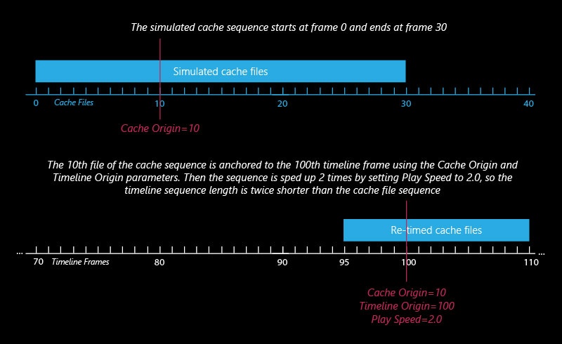
Example: Cache Origin and Play Speed
The following example demonstrates how the Cache Origin and Play Speed can be used to offset and speed up the input cache files.
The files go from simulationFrame_000 to simulationFrame_030. When the Timeline Origin is set to 100, they are read as if they were saved as simulationFrame_100 to simulationFrame_130.
The Cache Origin is then used to specify which simulationFrame will be placed on Timeline Origin = 100. Because Cache Origin is set to 10, the whole sequence is shifted 10 frames back such that simulationFrame_000 is placed at frame 90. Thus, the sequence now goes from frame 90 to frame 120.
The Play Speed is then set to 2.0. Those thirty frames are now reduced to fifteen. The Cache Origin frame is treated as the middle point when shrinking the sequence.
Example: Looping a Simulation
The following example demonstrates how the Input roll-out parameters can be used to loop a simulation.
The Timeline Origin parameter is set to 0 - this will be the first frame of the timeline which the Input Path files read into the scene by the Simulator will be placed on.
The Cache Origin is set to 10 so simulationFrame_010 will be read and placed at Timeline Origin = 0.
The Play Length is set to 15 so the sequence now repeats itself every 15 frames when played back (those are actually simulationFrame_010 to simulationFrame_025).
Finally, the Loop Overlap parameter is set to 5 to provide a few extra frames for blending the start and end of the loop together in a smooth transition.

Example: Play Speed
Channel Smoothing
Smoothing is performed after the cache file is loaded for the current frame, so for large grids it could cause significant lag after changing frames.
The controls in this section allow you to smooth the grid channels loaded from cache files for preview and rendering. You can use this to prevent grid artifacts on meshed grid channels such as the Liquid surface, Smoke or Temperature, to remove unwanted noise in these channels, or to get smooth motion blur by smoothing the Velocity grid channel.
Threshold | inSmoothTemp[0], inSmoothSmoke[0], inSmoothUVW[0], inSmoothFuel[0], inSmoothVel[0] – If this value is 0, the entire grid will be smoothed evenly. The higher the threshold is raised, the less voxels will be affected and only the sharpest gradients will be smoothed. The highest value you could use here depends on the range of the values of the smoothed channel - for Smoke and Liquid it's usually in the [0,1] range, while for Velocity it could go as high as several hundred and for Temperature it could be over a thousand. If you set this value too high, no voxels will be smoothed at all.
Similarity | inSmoothTemp[1], inSmoothSmoke[1], inSmoothUVW[1], inSmoothFuel[1], inSmoothVel[1] – Increasing this value will allow you to smooth only the finer small-scale noise without changing the areas of the fluid which are already smooth. Note that just like the Threshold option, this value also depends on the range of the selected channel. If you want to remove only some sharp fine disturbances from the simulation without blurring other areas, set the Threshold to 0, increase the Similarity to the highest values the selected channel can take and then start reducing it until the small-scale noise is removed, while the larger fluid shapes are retained. This option won't take effect if the Threshold parameter is raised to the maximum.
Random Variation | inSmoothTemp[2], inSmoothSmoke[2], inSmoothUVW[2], inSmoothFuel[2], inSmoothVel[2] – This parameter introduces noise of uniform scale in the channel before smoothing is applied. This can be useful if you want to give the fluid a more homogeneous pattern and this way it can also help hide grid artifacts. Note that just like the Threshold option, this value also depends on the range of the selected channel. You can use this option to only add noise to the channel without smoothing it - in order to do this, set both Threshold and Similarity to the highest values of the selected channel and this way they will not take effect.
Enable | inSmoothTempEnbl, inSmoothSmokeEnbl, inSmoothUVWEnbl, inSmoothFuelEnbl, inSmoothVelEnbl – This checkbox enables frame smoothing for the specified input channel.

3rd Party Channels Mapping
Different applications use different channels and might have different names for them. When loading f3d/vdb files, the V-Ray Volume Grid tries to automatically make the conversion to the supported channels. If a channel is not mapped by default, a channel can be manually set from the drop-down menu.
All mappings are kept in a single string attribute, accessible by the name "userChannelMappings". An example mapping string is:
2,density;10,fuel;1,temperature;4,vel.x;5,vel.y;6 ,vel.z;
The string is composed of pairs of a channel index and a string channel name.The following channels with the respective indices are supported:
Smoke - 2
Temperature - 1
Fuel - 10
Velocity.x - 4
Velocity.y - 5
Velocity.z - 6
Red - 7
Green - 8
Blue - 9
Wavelet Energy - 14
Wavelet.u - 19
Wavelet.v - 20
Wavelet.w - 21

Using Environment Variables with Volume Grid Paths
There are path environment variables in every OS, and they can be used with Volume Grid cache file paths.
For example, to access environment variables in Windows 10 and Windows 8, follow these steps:
- In Search, search for and then select System (Control Panel).
- Click the Advanced system settings link.
- Click the Environment Variables... button.
- In the System variables section, using Edit System Variable (or New System Variable) window, specify the value of the PATH environment variable.
Using this, you can create a path (variable), give it a name, and use it for cache files in the V-Ray Volume Grid.
For example, the path D:\V-Ray\Cache can be given the environment variable name "Cache". In the Volume Grid Input rollout, you can specify the path as the following:
$env(Cache)\cache_name###.aur
This will load the cache files in D:\V-Ray\Cache.
Note that in order to reference environment variables, the following pattern must be used:
$env(<variable_name>)