Versions Compared

Key

  • This line was added.
  • This line was removed.
  • Formatting was changed.

This page contains information about the V-Ray Edges Texture.


Overview


Section
Column
width50%

Edges achieves an effect similar to wireframes. Since it is a texture, is allows for interesting effects that are not possible with the standard materials. The texture can also be used as a bump map to produce a "round corners" effect for mesh objects.

Column
width5%


Column
width45%


UI Paths


Section
Column
width33%

||mat Network|| > V-Ray> Texture: Procedural > V-Ray Edges

Column
width33%
||out Network|| > V-Ray Render Elements node > V-Ray > Texture: Procedural > V-Ray Edges
Column
width33%


Node


Section
Column
width50%

The TexEdges node provides inputs for controlling various texture properties. They correspond to parameters in the section below.

Column
width5%


Column
width45%


Parameters


Section
Column
width50%

Edges Color  – Specifies the color of the edges.

Background Color –Specifies the color of the faces.

Width Type –Specifies the unit of measurement for the thickness of the edges

World – Thickness of the edges is measured in world (scene) units.
Pixels – Thickness of the edges is measured in pixels.

Width – Specifies the thickness of the edges in pixels.

Show Hidden edges – When enabled, this render all edges of the object. When disabled, only edges marked as "visible" are rendered. For more information, please see the Show Hidden Edges Parameter example below.

Show Sub-triangles – When enabled, edges generated by displacement mapping or render time subdivision are visible.

World Width – Specifies the thickness of the edges in world units.

Raytraced – When enabled, uses raytracing to compute the rounded corners. When disabled, uses static mesh analysis.

Consider Same Object Only – When enabled, the rounded corners are produced only along edges that belong to the same object which has the map applied. When disabled, rounded corners are produced along edges formed when the object with the edges map intersects other objects in the scene. For more information, please see the Consider Same Object Only Parameter example below.

Mode – Specifies which corners should have rounded edges applied to them. For more information, please see the Mode Parameter example below.

Convex and Concave – The effect is applied to both convex and concave edges.
Convex only – The effect is applied only to convex edges.
Concave only – The effect is applied only to concave edges.

Column
width5%


Column
width45%


Anchor
HiddenEdges
HiddenEdges


Example: Show Hidden Edges parameter


Section
Column
width10%


Column
width80%
Before after
afterLabelon
beforeLabeloff
Panel
borderStylenone

Panel
borderStylenone

Column
width10%


Anchor
ConsiderSameObject
ConsiderSameObject


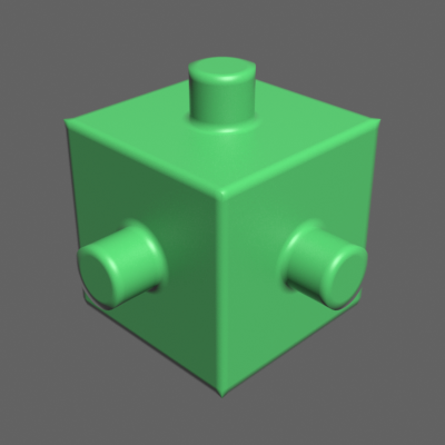
Example: Consider Same Object Only parameter


In this example, the cube and the cylinders are separate objects in the scene.


Section
Column
width10%


Column
width40%

Consider Same Object Only is on. The rounded corners effect is applied to each object individually.


Column
width40%

Consider same object is off. The rounded corners effect is applied between the different objects.


Column
width10%


Anchor
corners
corners


Example: Mode parameter


Section
Column
width15%


Column
width60%
Image slider
Panel
borderStylenone

Convex and Concave corners

Panel
borderStylenone

Convex corners only

Panel
borderStylenone

Concave corners only

Column
width15%