![]()
Page History
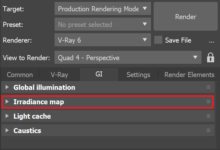
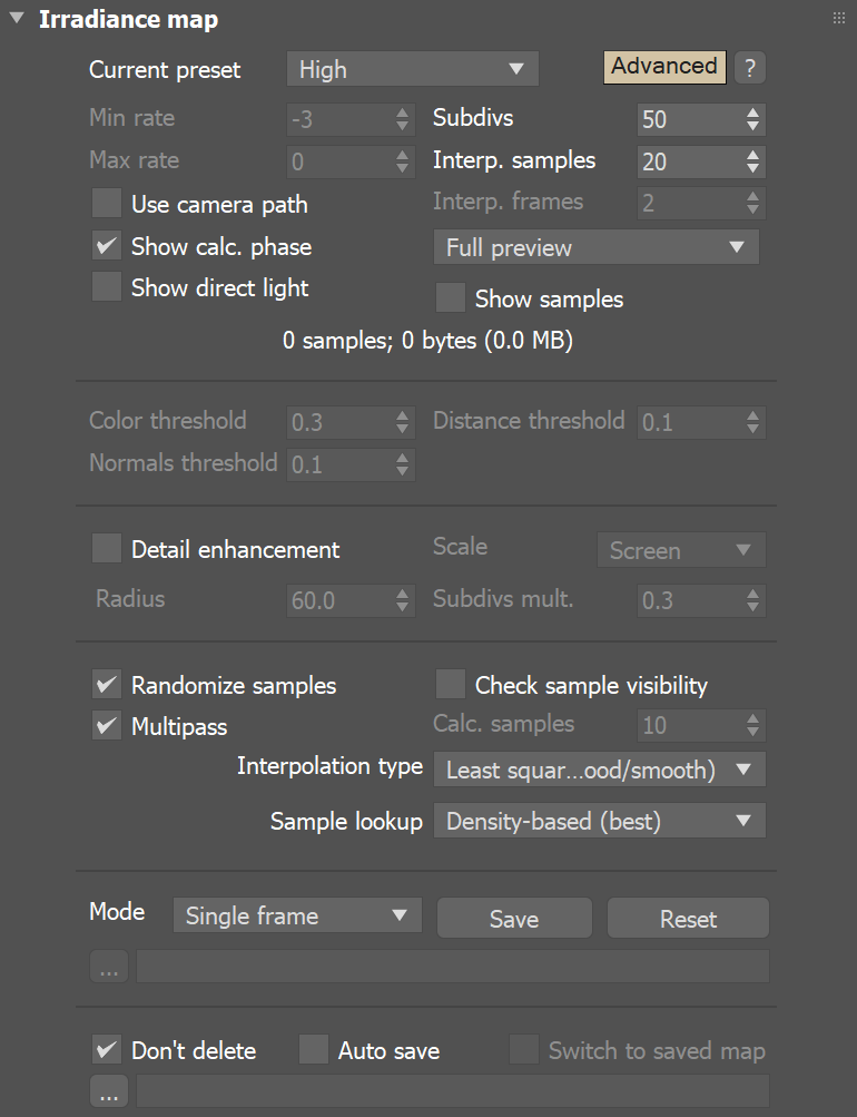
This page provides information on the Irradiance map rollout.
Overview
...
| Section | |||||||||||||||||||||
|---|---|---|---|---|---|---|---|---|---|---|---|---|---|---|---|---|---|---|---|---|---|
|
Default Parameters
...
| Section | |||||||||||||||||
|---|---|---|---|---|---|---|---|---|---|---|---|---|---|---|---|---|---|
|

| Anchor | ||||
|---|---|---|---|---|
|
...
Example: The Max Rate and Control of Detail
...
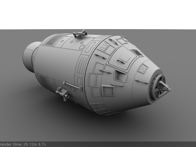
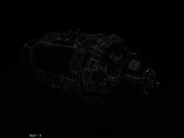
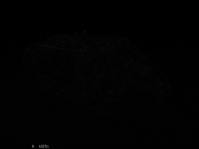
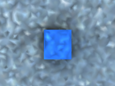
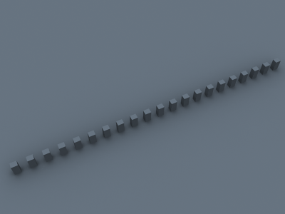
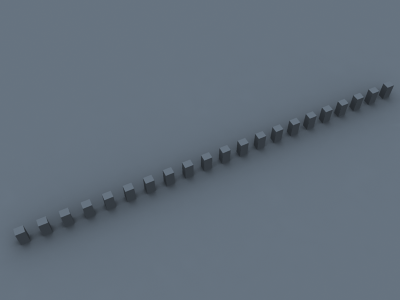
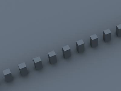
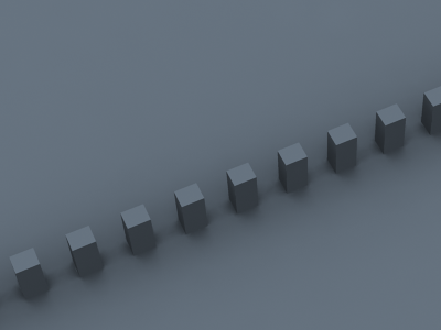
The following examples show how the Max rate of the irradiance map determines the detail in the GI solution. The scene contains small details with sizes less than a pixel.
...
Choosing an appropriate Max rate depends on what details you have in your scene and on the desired quality. If the image contains relatively flat surfaces with little detail, you can use a lower Max rate. If the scene contains a lot of small sub-pixel details, you need a higher Max rate too. Above a certain point of detailness, the irradiance map becomes too slow and in that case, brute force GI might perform better.
| Section | |||||||||||||||
|---|---|---|---|---|---|---|---|---|---|---|---|---|---|---|---|
|
| Section | |||||||||||||||||
|---|---|---|---|---|---|---|---|---|---|---|---|---|---|---|---|---|---|
|
| Section | |||||||||||||||
|---|---|---|---|---|---|---|---|---|---|---|---|---|---|---|---|
|

...
| Section | |||||||||||||||
|---|---|---|---|---|---|---|---|---|---|---|---|---|---|---|---|
|

...
...
Advanced Parameters
...
| Section | |||||||||||||||||||||||||||
|---|---|---|---|---|---|---|---|---|---|---|---|---|---|---|---|---|---|---|---|---|---|---|---|---|---|---|---|
|
| Anchor | ||||
|---|---|---|---|---|
|
...
Example: Check Sample Visibility
...
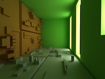
The following examples demonstrate the effect of the Check sample visibility parameter. The scene is a thin wall lit on the two sides by two V-Ray area lights with different color. Both lights had the Store with irradiance map option checked. The two images are rendered with the Medium irradiance map preset.
| Section | |||||||||||||||||||||||||||||||||
|---|---|---|---|---|---|---|---|---|---|---|---|---|---|---|---|---|---|---|---|---|---|---|---|---|---|---|---|---|---|---|---|---|---|
|

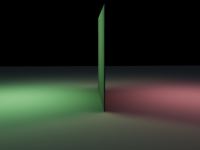
Notice the light leak in the first image. This happens because near the thin wall V-Ray uses samples from both the sides. When Check sample visibility is turned on, V-Ray discards the samples from the wrong side.
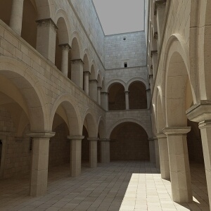
As a comparison, here is the same image rendered with the High irradiance map preset and Check sample visibility turned Off.
| Section | ||||||||||||||||||||||
|---|---|---|---|---|---|---|---|---|---|---|---|---|---|---|---|---|---|---|---|---|---|---|
|


The light leak effect is negligible in the left image and completely absent in the right one. This is because the High irradiance map preset causes V-Ray to take additional samples at the base of the thin wall, thus decreasing the leaking effect. Using a non-blurry interpolation method (Delone triangulation) further limits this effect.
The conclusion is that turning on Check sample visibility is only useful for low irradiance map settings. Also note that this option may not work very well for curved objects.
| Anchor | ||||
|---|---|---|---|---|
|
...
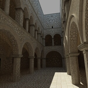
Example: The Delone Triangulation Method
...
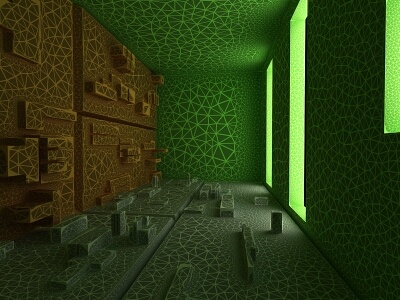
This example shows the triangles used by the Delone triangulation method to interpolate samples in the irradiance map. Note that the triangles are constructed on the fly from the irradiance samples; no actual mesh is ever created. The vertices of the shown triangles correspond to samples in the irradiance map.
| Section | ||||||||||||||||||||||
|---|---|---|---|---|---|---|---|---|---|---|---|---|---|---|---|---|---|---|---|---|---|---|
|


| Anchor | ||||
|---|---|---|---|---|
|
...
Example: Interpolation Methods
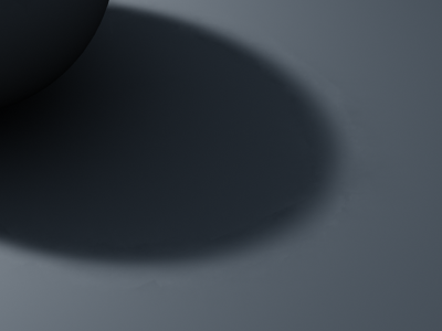
The following examples shows the main differences between a blurry interpolation method (Least squares fit) and a non-blurry one (Delone triangulation). Notice how the images in the first column are more blurry, while the images in the second column are sharper.
| Comment | Blurry method (Least squares fit) | Non-blurry method (Delone triangulation) |
|---|---|---|
| The scene is a simple cube on a sphere as seen from above, lit by a HDRI map. Low hemispheric subdivs and low irradiance map rates were used intentionally so that the difference is more obvious. Both images were rendered with exactly the same irradiance map. |
|
|
| This scene shows the ability of the Delone triangulation method to preserve detail. Notice that the shadows in the right image are sharper. Both images used the same irradiance map. |
|
|
| A close-up of the previous scene. The irradiance map is exactly the same as for the two previous images (it was saved and then loaded from disk). |
|
|

...
| Anchor | ||||
|---|---|---|---|---|
|
...
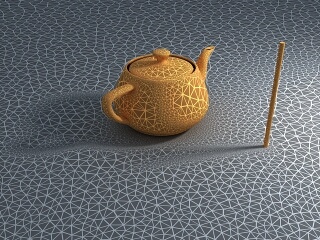
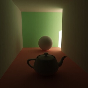
Example: Sample Look-up
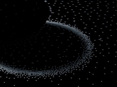
The following examples show the differences between the three sample lookup methods and more specifically, their behavior in areas with changing sample density.
This is the test scene, the left image shows the final image and the right image shows the samples in the irradiance map (it was rendered with the Show samples option checked). The scene itself is a sphere on a plane, lit by a V-Ray area light and a little skylight. The area light had the option Store with irradiance map checked
| Section | ||||||||||||||||||||||
|---|---|---|---|---|---|---|---|---|---|---|---|---|---|---|---|---|---|---|---|---|---|---|
|

...
As one will notice, the density of the samples is quite different in the uniformly lit areas and in the shadow transition area. The following three images used exactly the same irradiance map with the Least squares fit interpolation method.
| Section | |||||||||||||||||||||||||||
|---|---|---|---|---|---|---|---|---|---|---|---|---|---|---|---|---|---|---|---|---|---|---|---|---|---|---|---|
|


You can see the ringing artifacts (the white halo around the shadow) caused by the different sample density in the first two images. The last image, rendered with the Precalculated overlapping method is free from those artifacts. It also rendered faster than the other two images.
As a comparison, here is the same image rendered with the Delone triangulation interpolation method.
| Section | |||||||||||||||||||||||||||
|---|---|---|---|---|---|---|---|---|---|---|---|---|---|---|---|---|---|---|---|---|---|---|---|---|---|---|---|
|


...
The images are nearly identical. This is because the Delone triangulation method, being a non-blurry method, is less sensitive to the samples that are being looked up, so long as the delone trianglulation can be performed successfully from them.
...
Switch to saved map – Only available if the Auto save option is turned On. If Switch to saved map is on, then V-Ray also automatically sets the irradiance map mode to From file and sets the file name to be that of the map that was just saved.
Avoiding flickering in animations
...
| Fancy Bullets | ||
|---|---|---|
| ||
|
...
Note that completely removing flickering artifacts arising from the irradiance map may be difficult or impossible. Using the Brute force GI engine as a primary GI engine may be the best and fastest option (with the secondary GI engine set to either Light cache or again Brute force).
Notes
...
| Fancy Bullets | ||
|---|---|---|
| ||
|