![]()
Page History
This page provides information on the Occlusion or Dirt Map.
Overview
...
| Section | ||||||||||||||||||||||||
|---|---|---|---|---|---|---|---|---|---|---|---|---|---|---|---|---|---|---|---|---|---|---|---|---|
|


Parameters
...
| Section | ||||||||||||||||||||||||||||||||||||||||
|---|---|---|---|---|---|---|---|---|---|---|---|---|---|---|---|---|---|---|---|---|---|---|---|---|---|---|---|---|---|---|---|---|---|---|---|---|---|---|---|---|
|

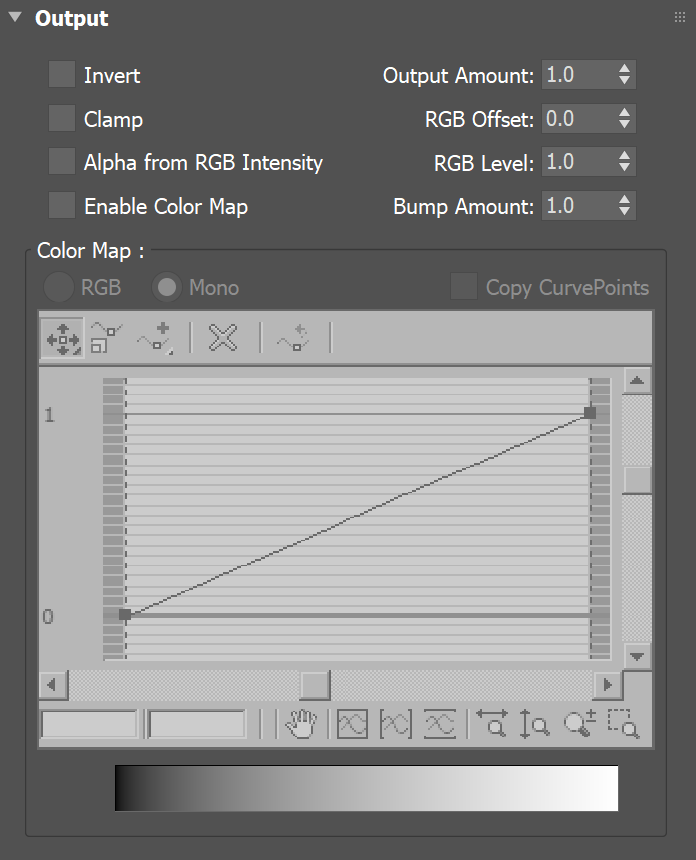
Output Settings
...
| Section | |||||||||||||||
|---|---|---|---|---|---|---|---|---|---|---|---|---|---|---|---|
|
| Anchor | ||||
|---|---|---|---|---|
|
...
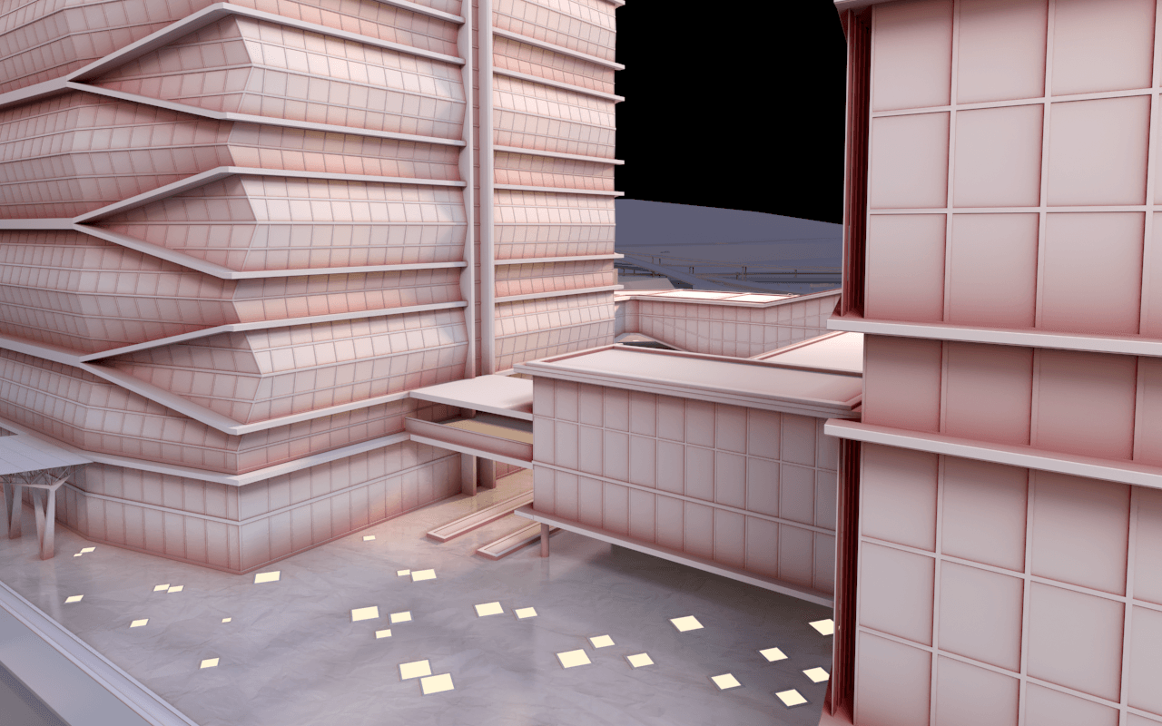
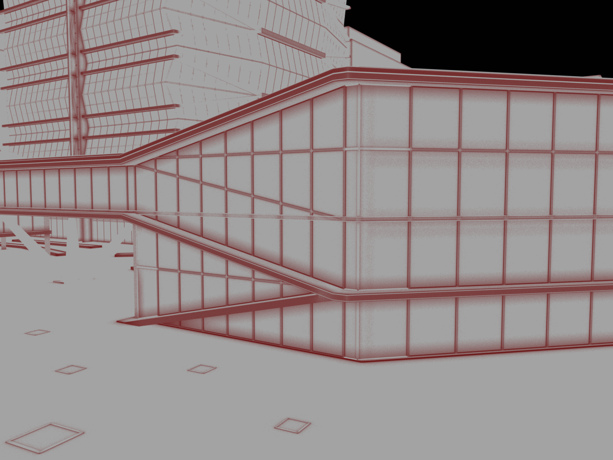
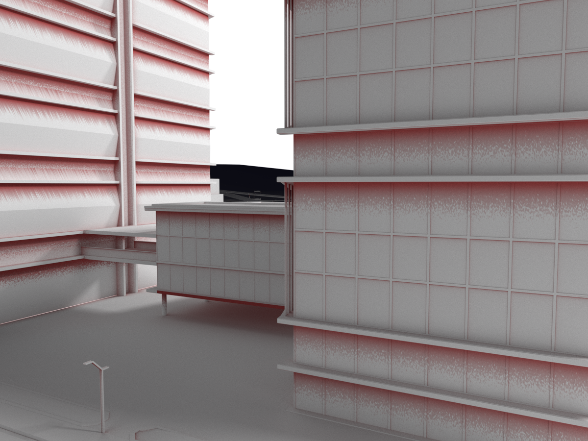
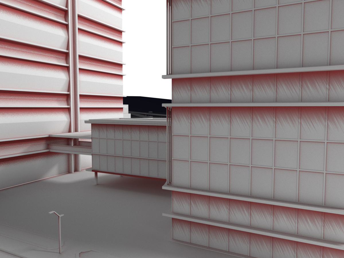
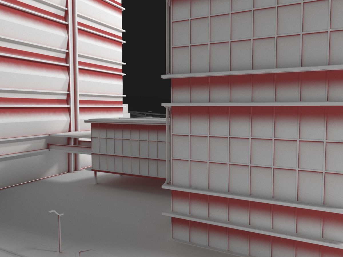
Example: Radius Parameter
This parameters parameter determines the amount of area (in units) where the VRayDirt effect is produced. the The Dirt color has been tinted red to clarify the effect. The scene used for these examples is a small paper 1/100th scale-model of the architecture.
...
| Section | ||||||||||||||||||||||||||||||||
|---|---|---|---|---|---|---|---|---|---|---|---|---|---|---|---|---|---|---|---|---|---|---|---|---|---|---|---|---|---|---|---|---|
| ||||||||||||||||||||||||||||||||
|


| Anchor | ||||
|---|---|---|---|---|
|
...
In the next example, a bitmap is used in the Radius texture map slot. Notice that the main Radius parameter still has effect - it determines the amount of area where the bitmap would blend. In the first image, the Radius parameter is set to 1 cm, and in the second image it is set to 4 cm.
...
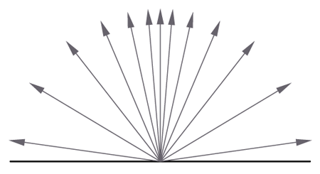
Example: Distribution Parameter
...
The Distribution parameter
...
forces the rays to gather closer. The effect is that the dirt area is being narrowed closer to the contact edges.
| Section | ||||||||||
|---|---|---|---|---|---|---|---|---|---|---|
| ||||||||||
|

...
Example: Subdivisions Parameter
To better illustrate this the Subdivs parameter, the VRayDirt material has been assigned as a diffuse map to VRayMtl. theThe Diffuse Filter Render Element has been rendered to clearly display the diffuse effect.
...
| Anchor | ||||
|---|---|---|---|---|
|
...
Example: Bias
...
This parameter biases the normals so that the dirt effect is forced to some of the axis(es).
| Section | ||||||||||||||||||||||||||||||||
|---|---|---|---|---|---|---|---|---|---|---|---|---|---|---|---|---|---|---|---|---|---|---|---|---|---|---|---|---|---|---|---|---|
| ||||||||||||||||||||||||||||||||
|


| Anchor | ||||
|---|---|---|---|---|
| ||||
|
...
| Section | ||||||||||||||||||||||||||||||||||
|---|---|---|---|---|---|---|---|---|---|---|---|---|---|---|---|---|---|---|---|---|---|---|---|---|---|---|---|---|---|---|---|---|---|---|
| ||||||||||||||||||||||||||||||||||
|


...
| Anchor | ||||
|---|---|---|---|---|
|
| Section | ||||||||||||||||||||||||||||||||
|---|---|---|---|---|---|---|---|---|---|---|---|---|---|---|---|---|---|---|---|---|---|---|---|---|---|---|---|---|---|---|---|---|
|


| Anchor | ||||
|---|---|---|---|---|
|
| Anchor | ||||
|---|---|---|---|---|
|
| Anchor | ||||
|---|---|---|---|---|
|
...
| Section | ||||||||||||||||||||
|---|---|---|---|---|---|---|---|---|---|---|---|---|---|---|---|---|---|---|---|---|
|
...
|
| Section | ||||||||||||||||||||||||||||||||||||||||||||
|---|---|---|---|---|---|---|---|---|---|---|---|---|---|---|---|---|---|---|---|---|---|---|---|---|---|---|---|---|---|---|---|---|---|---|---|---|---|---|---|---|---|---|---|---|
| ||||||||||||||||||||||||||||||||||||||||||||
|


...
| Section | ||||||||||||||||||||||||||||||||
|---|---|---|---|---|---|---|---|---|---|---|---|---|---|---|---|---|---|---|---|---|---|---|---|---|---|---|---|---|---|---|---|---|
Example: Thin modeEnhances the look of thin surfaces by casting less dirt on them. Available only for Inner occlusion mode.
|

| Anchor | ||||
|---|---|---|---|---|
|
...
| Section | ||||||||||||||||||||||||||
|---|---|---|---|---|---|---|---|---|---|---|---|---|---|---|---|---|---|---|---|---|---|---|---|---|---|---|
|
| Section | |||||||||||||||||||||||||||||||||||||||||||||||||
|---|---|---|---|---|---|---|---|---|---|---|---|---|---|---|---|---|---|---|---|---|---|---|---|---|---|---|---|---|---|---|---|---|---|---|---|---|---|---|---|---|---|---|---|---|---|---|---|---|---|
| |||||||||||||||||||||||||||||||||||||||||||||||||
|


| Anchor | ||||
|---|---|---|---|---|
|
...
| Section | ||||||||||||||||||||||||||||||||||||||||||||||||||||||
|---|---|---|---|---|---|---|---|---|---|---|---|---|---|---|---|---|---|---|---|---|---|---|---|---|---|---|---|---|---|---|---|---|---|---|---|---|---|---|---|---|---|---|---|---|---|---|---|---|---|---|---|---|---|---|
|


Notes
...
| Fancy Bullets | ||
|---|---|---|
| ||
|