![]()
Page History
...
| UI Text Box | ||
|---|---|---|
| ||
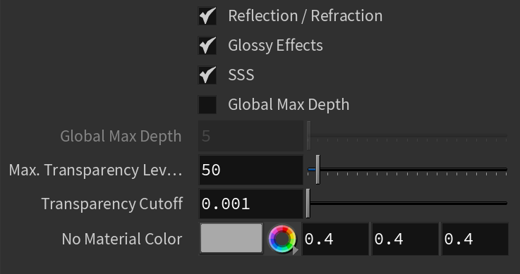
When CUDA/RTX is chosen as a rendering engine, all unsupported options are disabled from the parameters. |
UI Path:
||V-Ray Shelf|| > ROP Parm > Renderer tab > Options tab
||out Network|| > V-Ray > V-Ray Renderer > Renderer tab > Options tab
V-Ray menu > Render Settings > Renderer tab > Options tab
Geometry
...
| Section | |||||||||||||||||||||
|---|---|---|---|---|---|---|---|---|---|---|---|---|---|---|---|---|---|---|---|---|---|
|

Lights
...
| Section | |||||||||||||||||||||||||||||||
|---|---|---|---|---|---|---|---|---|---|---|---|---|---|---|---|---|---|---|---|---|---|---|---|---|---|---|---|---|---|---|---|
|

Materials
...
| Section | |||||||||||||||
|---|---|---|---|---|---|---|---|---|---|---|---|---|---|---|---|
|
Textures
| Section | |||||||||||||||
|---|---|---|---|---|---|---|---|---|---|---|---|---|---|---|---|
|
Volumetrics
| Section | |||||||||||||||
|---|---|---|---|---|---|---|---|---|---|---|---|---|---|---|---|
|
|
Textures
...
| Section | |||||||||||||||
|---|---|---|---|---|---|---|---|---|---|---|---|---|---|---|---|
|
Volumetrics
...
| Section | |||||||||||||||
|---|---|---|---|---|---|---|---|---|---|---|---|---|---|---|---|
|

...
Rendering
...
| Section | |||||||||||||||
|---|---|---|---|---|---|---|---|---|---|---|---|---|---|---|---|
|
Raycaster
| ||||||||||||||||||||||||||||
| Section | ||||||||||||||||||||||||||||
|---|---|---|---|---|---|---|---|---|---|---|---|---|---|---|---|---|---|---|---|---|---|---|---|---|---|---|---|---|
Default Geometry – Determines the type of geometry for polygonal data. You can choose between Auto, Static and Dynamic. Auto – Some objects are compiled as static geometry, while others as dynamic. V-Ray makes the decision on which type to use based on the face count for an object and the number of its instances in the scene.Static – All geometry is precompiled into an acceleration structure at the beginning of the rendering and remains there until the end of the frame. The static raycasters are not limited in any way and will consume as much memory as necessary. Dynamic – Geometry is loaded and unloaded on the fly depending on which part of the scene is being rendered. The total memory taken up by the dynamic raycasters can be controlled by the Dynamic memory limit parameter
Output Directory – Specifies a location where the profiler reports are created. File Suffix – Specifies a suffix that is appended at the end of the profiler report files. For more information, see the V-Ray Profiler page. Memory TrackingEnable Memory Tracking – Enables tracking of how much memory is used by V-Ray for different categories of objects like textures, geometry, GI, image sampling, etc. Enabling this option generates .html reports with detailed information on memory usage. Output Directory – Specifies the location to save the memory reports after the rendering is finished. File Suffix – Specifies a text that is appended to the Memory Tracking result file names.
|

...
Raycaster
...
| Section | |||||||||||||||
|---|---|---|---|---|---|---|---|---|---|---|---|---|---|---|---|
|
VFB
| Section | |||||||||||||||
|---|---|---|---|---|---|---|---|---|---|---|---|---|---|---|---|
|
UI
| Section | |||||||||||||||
|---|---|---|---|---|---|---|---|---|---|---|---|---|---|---|---|
|
...
Example: Secondary Rays Bias
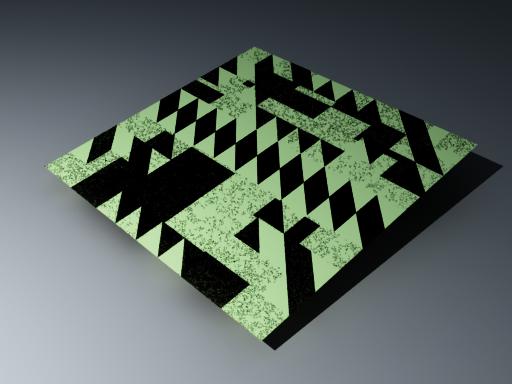
This example shows the effect of the Secondary rays bias parameter. The scene below has a box object with a height of 0.0, which the top and bottom of the box occupy exactly the same region in space. Due to this, V-Ray cannot resolve unambiguously intersections of rays with these surfaces.
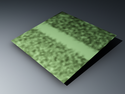
The first image shows what happens when you try to render the scene with the default settings. You can see the splotches in the GI solution, caused by the fact that rays randomly intersect one or the other surface:
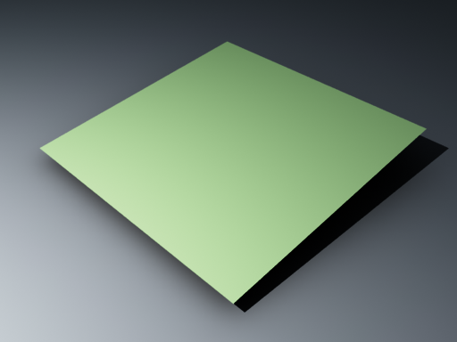
In the second image below, the Secondary rays bias is set to 0.001, which offsets the start of each ray a little bit along its direction. In effect, this makes V-Ray skip the problematic surface overlaps and render the scene correctly :
Note that the Secondary rays bias affects only things like GI, reflections, etc. In order to render the scene properly, the material assigned to the box has its 2-sided option checked. This is so that the object looks in the same way regardless of whether the camera rays hit the top or the bottom of the box. If the material did not have this option checked, it would appear "noisy" even though the Secondary rays bias is greater than 0.0:
...
Example: Adaptive Lights
Below is an example rendering of a scene with the default Bucket Image Sampler settings, using Brute Force/Light Cache GI engines. Only the Threshold parameter was set to 0.001. Notice how the render time is reduced significantly in favor of the Adaptive Lights in comparison to Full Evaluation.
| Section | ||||||||||||||||||||||||||||||||
|---|---|---|---|---|---|---|---|---|---|---|---|---|---|---|---|---|---|---|---|---|---|---|---|---|---|---|---|---|---|---|---|---|
|


...
|

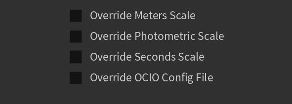
Units
...
| Section | |||||||||||||||
|---|---|---|---|---|---|---|---|---|---|---|---|---|---|---|---|
|
VFB
...
| Section | |||||||||||||||
|---|---|---|---|---|---|---|---|---|---|---|---|---|---|---|---|
|

UI
...
| Section | |||||||||||||||
|---|---|---|---|---|---|---|---|---|---|---|---|---|---|---|---|
|

Example and Workflows
...
| Anchor | ||||
|---|---|---|---|---|
|
Example: Secondary Rays Bias
This example shows the effect of the Secondary rays bias parameter. The scene below has a box object with a height of 0.0, which the top and bottom of the box occupy exactly the same region in space. Due to this, V-Ray cannot resolve unambiguously intersections of rays with these surfaces.
The first image shows what happens when you try to render the scene with the default settings. You can see the splotches in the GI solution, caused by the fact that rays randomly intersect one or the other surface:
In the second image below, the Secondary rays bias is set to 0.001, which offsets the start of each ray a little bit along its direction. In effect, this makes V-Ray skip the problematic surface overlaps and render the scene correctly:
Note that the Secondary rays bias affects only things like GI, reflections, etc. In order to render the scene properly, the material assigned to the box has its 2-sided option checked. This is so that the object looks in the same way regardless of whether the camera rays hit the top or the bottom of the box. If the material did not have this option checked, it would appear "noisy" even though the Secondary rays bias is greater than 0.0:
| Anchor | ||||
|---|---|---|---|---|
|
...
Example: Adaptive Lights
Below is an example rendering of a scene with the default Bucket Image Sampler settings, using Brute Force/Light Cache GI engines. Only the Threshold parameter was set to 0.001. Notice how the render time is reduced significantly in favor of the Adaptive Lights in comparison to Full Evaluation.
| Section | |||||||||||||||||||||||||||||||
|---|---|---|---|---|---|---|---|---|---|---|---|---|---|---|---|---|---|---|---|---|---|---|---|---|---|---|---|---|---|---|---|
|
...
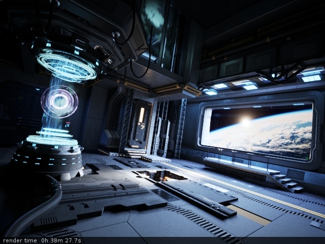
Example: Use Embree
The Embree raycaster process dynamically builds algorithms that best match the instruction set of the CPU, thus speeding up the raycasting process overall. Currently in V-Ray, the Embree process accelerates only the calculation of rays for static geometry (as opposed to dynamic or render-time geometry).
VRayProxy objects, VRayFur and all hair geometry are not currently accelerated with Embree, although support for VRayProxy objects is planned for a future release.
The following images were rendered with the Progressive image sampler over a set period of time. Using Intel® Embree allowed the progressive sampler to compute almost twice as many passes within the rendering time, thus producing a smoother image.
| Section | ||||||||||||||||||||||
|---|---|---|---|---|---|---|---|---|---|---|---|---|---|---|---|---|---|---|---|---|---|---|
|