Page Contents
Introduction
This tutorial covers the basic workflow for creating a basic liquid simulation in Phoenix FD for 3ds Max. By the end of it, you will be able to create your own liquid simulation and know the basics of editing some of the main settings of the sim.
To follow this tutorial, you will need to have the Phoenix FD for 3ds Max plugin installed. This tutorial is a companion to go along with the QuickStart video posted on our YouTube channel and available here:
Tutorial Assets
To download the files used in this tutorial, please click the button below.
Tutorial Steps
This tutorial shows how to create a basic liquids simulation with both the toolbar preset and manually step-by-step for greater flexibility and control.
Tap Water Preset
We will begin by first using a quick preset.
To prepare your scene for rendering a simulation, make sure V-Ray is set as your Renderer in the Render Setup window.
![]()

Create a Sphere with a Radius of about 4.0 centimeters. This sphere will be the source of the liquid.
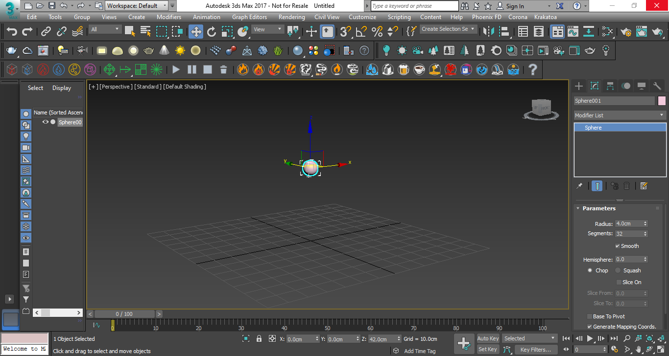
With the sphere selected, click on the Tap Water preset button from the Phoenix FD Toolbar.
![]()
Now select the Start Simulation button in the toolbar.
![]()
Click Stop Simulation to halt the simulation as it starts to fill the container.
![]()
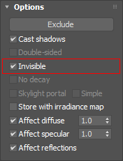
Add a Dome light to your scene and set it to be Invisible to make it easier to focus on the simulation.
Render the current frame. Note that the liquid fills the simulation volume container as it flows.
Manual Water Setup
Now we did that easily by using the tap water preset, so let’s take a look at setting this up manually to have more control.
If you are continuing from the preset steps above, select the liquid simulator and source objects and delete them from your scene. If not, create a Sphere with a Radius of about 4.0 centimeters.
Click on the Create a Liquid Simulator button in the toolbar, and click and drag in the viewport to create a volume to encompass the sphere and leave room for the liquid to fall. The volume should be about 50 x 65 x 100cm.
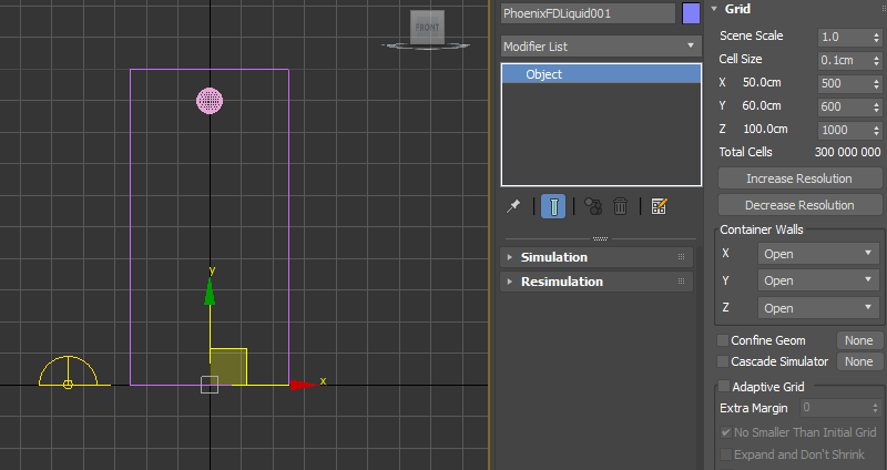
If necessary, adjust the size of the grid volume using the X size, Y size, and Z size parameters in the Grid rollout. Don't scale the grid as this will disrupt the relationship between the Cell size and X/Y/Z size parameters.
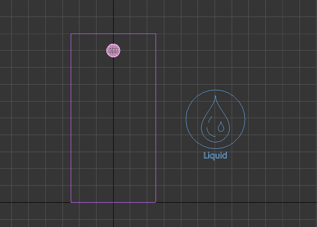
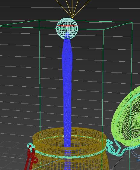
Move the sphere near the top of the simulator's volume space. Make sure the sphere is still inside the volume.
Click the Create a Liquid Source button on the toolbar and place the source anywhere in your scene.
![]()
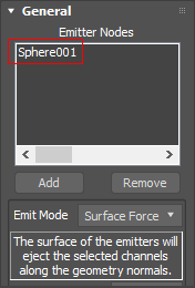
In the Command Panel for the Liquid Source object, Click the Add button, and select the sphere to add that to the Emitter Nodes list, enabling the sphere to be the emitter of the liquid.

Please note that scale is an essential factor in simulations. When creating your own scenes, be sure to build your scene in real world units. It’s a good idea to go into Units Setup in the Customize menu to check your settings and make sure that your units match.
Select the simulator. In the Modify Panel under the Grid rollout are parameters to control the resolution of the volume grid, which greatly affects the look and performance of the simulation. Increasing the Cell size reduces the overall resolution of the simulation shown in Total cells parameter, which gives you better performance. Decreasing Cell size increases the resolution making the sim look and act better, but at the cost of system performance. It’s always a good idea to go for the lowest Total cells possible that give you the look you need to maximize performance.
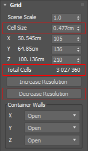
In the Grid rollout, click Decrease Resolution until the Total cells value is around 3-4 million cells. You can also set the Cell size to change the number of Total cells.
Click the Start Simulation icon to confirm that the sphere is emitting the liquid inside the Simulator. Stop the simulation when you are satisfied it is working.
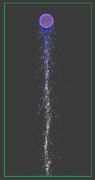
The simulation is currently all white. We can cause the particles to change color depending on their speed of travel. Select the Simulator and expand the Preview rollout. We will offset the White speed parameter by making it higher, introducing blue into the simulation where the particles are not traveling as fast as this value. Set White speed to a higher value such as 800 or 1200. The particles start off as blue (the default color next to the Show option) and become white after a few frames.
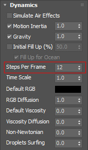
Now let’s get this to look more like what we had with the preset. Right now the edges of the pour are pretty jagged. Expand the Dynamics rollout and adjust the Steps per frame to 12. This provides for a more natural look but will make the sim run slower. The higher the Steps per frame, the longer the calculations, so try to find the lowest setting for the effect you need. And after letting the simulation run a bit, moving up to 12 Steps per frame addresses this ragged edge effect and helps smooth the shape of the pour.
As you can see, the liquid is flowing right through the floor and disappearing. This means our Simulator is open and needs to be closed. Open the Grid rollout, you can see the Container Walls are indeed all set to Open. Set the X, Y, and Z values to Jammed both.
Start the simulation again. As the simulation runs, the liquid will now collide with the bottom and the side walls of the Simulation.

It is, however, running slowly, so we can adjust the resolution to address that by increasing the Cell Size.
We currently have 3-4 million cells to calculate in the sim. Stop the sim, and click Decrease resolution until Total cells amount is about half a million cells.
Start the sim again and you’ll see it is running faster. While the sim is still running, go to the Dynamics rollout and set the Steps per frame to 1 to speed up the sim some more. Feel free to experiment with different settings and when you’re done, stop the sim.
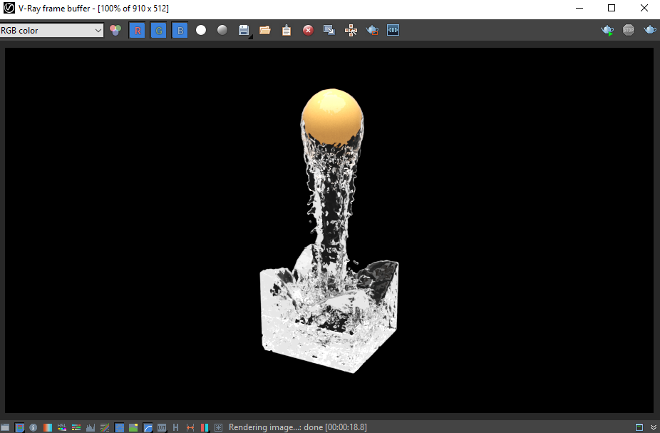
Render the result, and you’ll notice the water is a solid purple color. Let's create a water material to apply to the sim. Open the Material Editor, and create a new V-Ray Material. Set Diffuse to black, then set both Reflect and Refract to white. Enter an IOR value of 1.33 for water.
Assign the material to the Simulator, and render a frame.
![]()
Feel free to adjust the material and the lighting in the scene to achieve the liquid look you’re going for.
Applying the Sim Setup to a Real-world Example
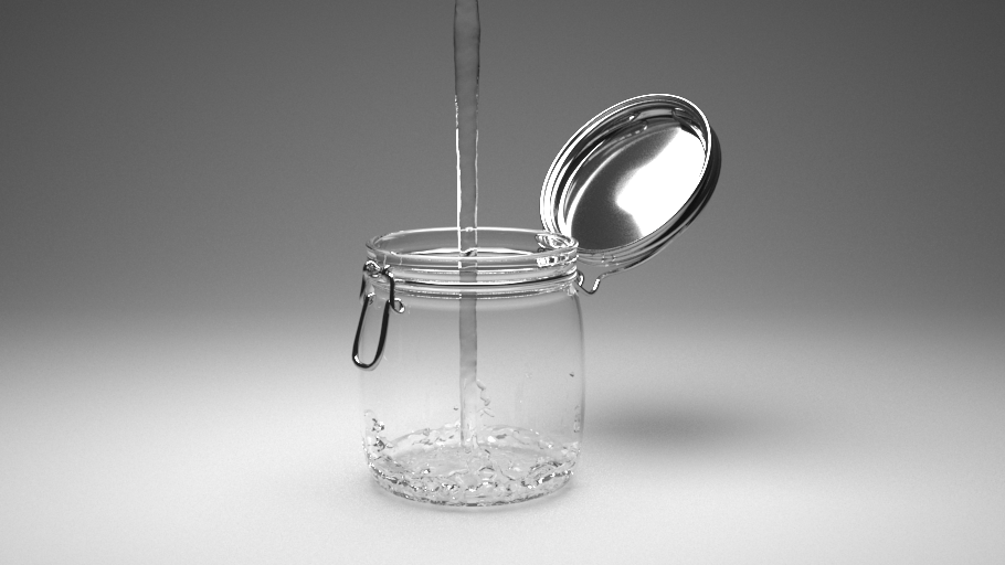
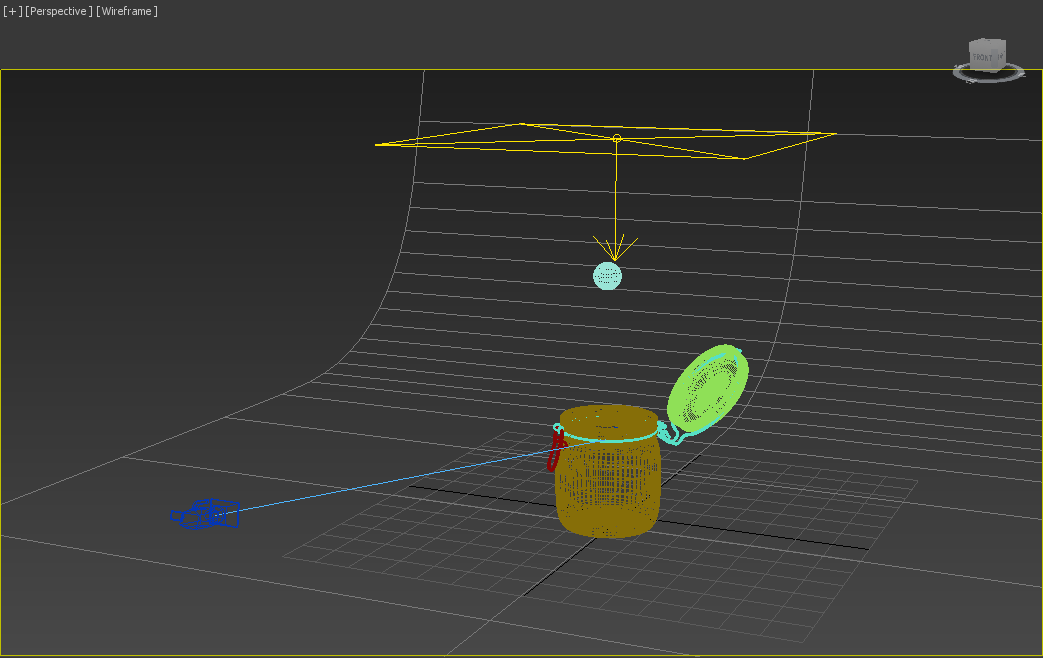
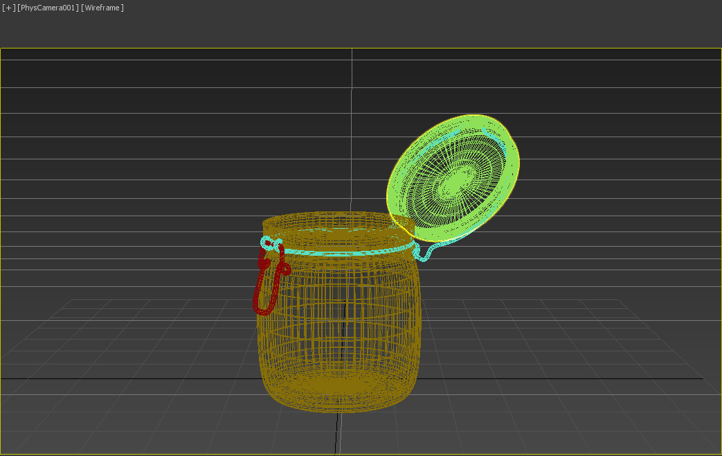
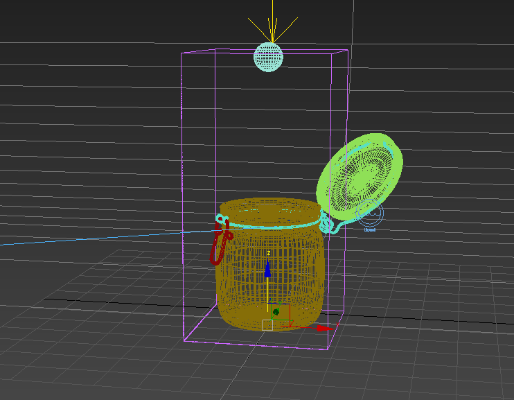
Now let’s make this liquid collide with and fill an actual object rather than just the simulator’s box-shaped grid. The following scene file can be downloaded from the Tutorial Assets section above. It consists of a jar with a studio lighting setup and background. Switch the view to PhysCamera001 to see what will be rendered.
Return to the perspective view and select the sphere. In the Phoenix FD toolbar, click the Tap Water Quick Preset like we did before.
We will need to adjust the simulator grid size and move it down to encompass both the sphere and the jar. Again, use the X/Y/Z size parameters in the Grid rollout. Using these parameters, as opposed to simply scaling the simulator, also changes the simulator resolution to add more detail as needed in larger containers.
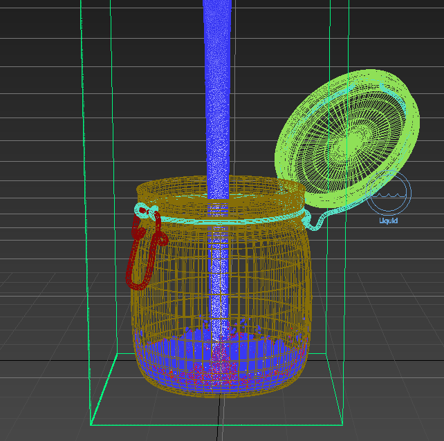
Start the simulation. Once it resolves, go back to the camera view. Here is how the simulation looks so far on frame 23:
Next, we will create materials for the water and glass jar. Open the Slate and create a V-Ray Material just like we did previously. Make sure the Diffuse is black, set the Reflection and Refraction both to white, and set the IOR to 1.33. Assign this material to the simulator.
Create another V-Ray Material for the glass jar. Set the Diffuse to black, set Reflection and Refraction both to white, but this time leave the IOR to 1.6. Select the glass part of the jar and assign this material.
Water V-Ray Material
Glass V-Ray Material
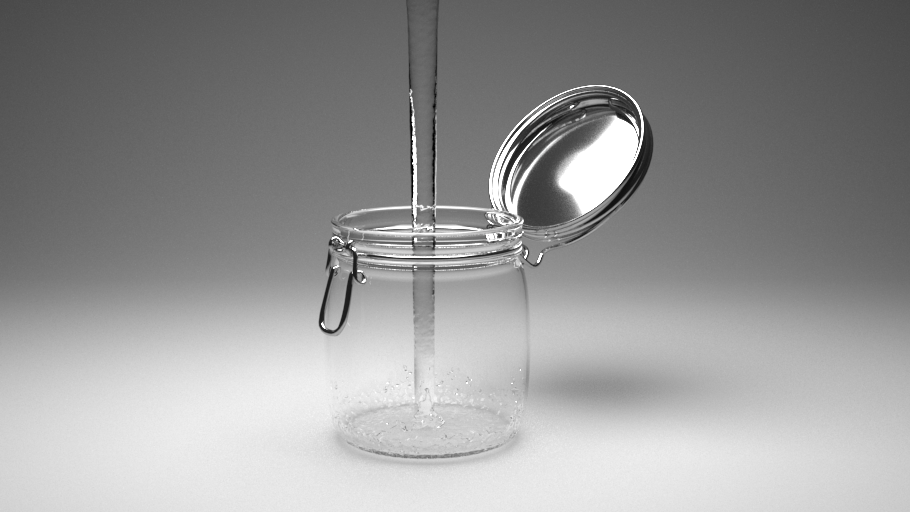
Render a frame to see how the fluid is interacting with the jar. Any geometry inside a simulation container will automatically interact with the emitting fluid. In addition, geometry can be excluded from interactions, and you can even create non-solid geometries, which are geometries that a simulation can flow through, but still be used as sources or forces acting on the simulation. This will be covered in upcoming videos.
With the current simulation, the fluid will eventually overflow the jar. To control how much fluid is discharged by the emitter, select the Liquid Source object and locate the Outgoing Velocity parameter. Animating this value will control how much liquid is created, which can be used to start and stop the pouring of water.
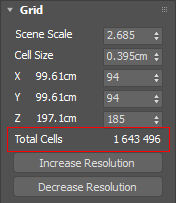
Before proceeding, let's lower the simulation resolution. Select the Simulator and navigate to the Grid rollout. Click the Decrease resolution button three times to lower the Total cells to around 1.6 million cells.
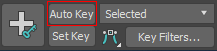
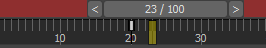
We will animate the pour next, so scrub through the timeline to return to the start. Select the Liquid Source and set the Outgoing Velocity to 16 . Note that if this value is set to 0.0 on the first frame, nothing will be emitted even if you start the simulation. Next, scrub ahead to frame 23 and click the Auto Key button.
Set the Outgoing Velocity to 0.0 at frame 23. With the current keys, the outgoing velocity will gradually decrease from 16 to 0, which is not the effect we want. Click and drag the key at frame 0 over to frame 20, so the liquid starts with a steady pour and then abruptly stops between frame 20 and 23.
Now that the pour animation is set, turn off Auto Key. Go back to the beginning and start the simulation.
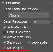
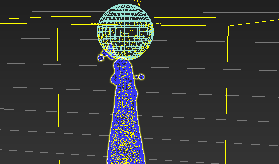
After the simulation resolves, you may notice that the result appears a little choppy if you scrub through the timeline. To fix this, select the simulator, go to the Preview rollout, and turn off Show Mesh. Only particles for the liquid pour will be displayed, and the simulation will scrub faster. At any point in the simulation, you can turn Show Mesh back on to see the liquid better.
Notice at around frame 30, at the top of the pour there is a large spread of drops coming out of the emitter. This is because the emission is coming from the surface of the sphere.
To fix this, select the Liquid source object, and change the Emit Mode to Volume Brush. What this means is that instead of emitting the liquid from the surface area of the sphere, it will now emit from the whole volume of the sphere.
A window will ask to convert the emitter to a Non-Solid object. Select Yes. This will prevent the sphere geometry from interacting with the liquid simulation.
Finally, select the simulator and under the Dynamics rollout, reduce Steps per frame to 5. We are ready to let the simulation run one last time.
Go to the start of the timeline and start the simulation. This time, notice that the spread out droplets are no longer an issue.
Return to the camera view and render a frame to see how the jar looks now. Here is a rendered frame of our final result: