In this chapter, we cover all render elements responsible for editing geometries from the scene.
The group of geometry render elements include:
- Bump Normals – Normals generated by bump maps in screen space (which is not the same as camera space). Type: RenderChannelBumpNormals
- Normals – Surface normals in screen space (which is not the same as camera space). Type: RenderChannelNormals
- Velocity – Surface velocity of an object. This render element is useful for generating motion blur in post-production. Type: RenderChannelVelocity
- Z-Depth – Z-depth of surfaces in the scene. Type: RenderChannelZDepth
Bump Normals
Type: RenderChannelBumpNormals
The Bump Normals Render Element creates a normal-style image from the camera view from bumps and normals in the scene.
The Bump Normals is a render element that stores the camera view as a normal map. The normals are generated using screen space which uses the XYZ orientation of the camera view. With Screen space, the X axis runs left-right across the view, Y runs up-down, and Z points out of the screen. Bump maps are also represented in this render element.
This render element is similar to the Normals (VRayNormals) Render Element that does not include bump maps. Also compare with Sampler Info (VRaySamplerInfo), which can render a normal map in object or world space in addition to camera (screen) space.
The Bump Normal Render Element is useful for adjusting lighting that comes from a particular direction. For example, faces of objects pointing toward the camera are predominantly blue in Bump Normals, so the lighting on such objects can be adjusted by using the blue channel in compositing software.
Parameters
The Bump Normals Render Element is accessible through the RenderChannelBumpNormals plugin.
- enableDeepOutput - Specifies whether to include this render element in deep images.
- name - (String) The name of the render element containing the denoised image.
- filtering – (Boolean) Whether the image filter is applied to this channel.
Common Uses
(used mainly for relighting)
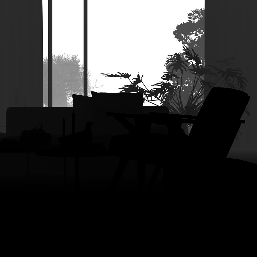
The Bump Normal Render Element is useful for changing the appearance of lighting in a scene in a composite without the need for rerendering. In the example below a lighting workflow is used at a composite level to change the lighting in the scene. Note that it does not create any extra shadowing. While the Bump Normal Render Element provides information about how lights will affect each surface; the Point Position element passes the spacial location of each pixel. When used together it allows lights added in composite to react on the pixels as if they were the surface of the model.
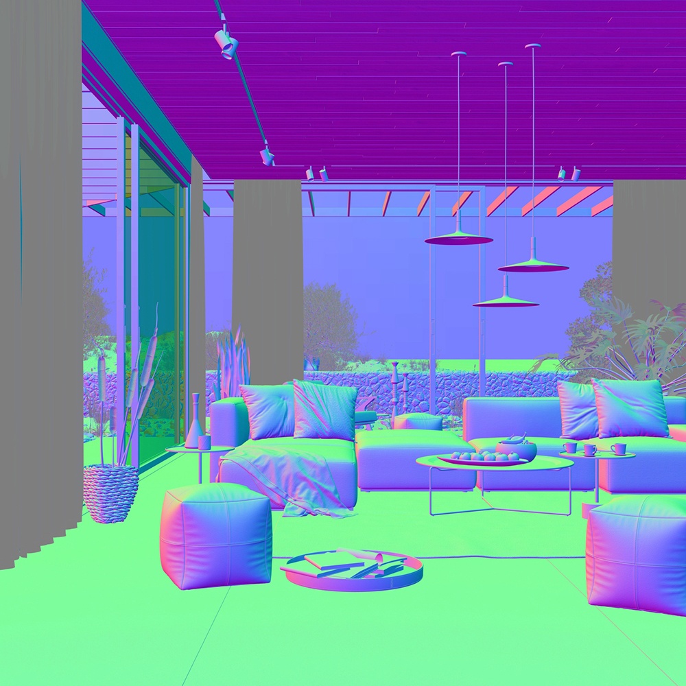
Bump Normals Render Element
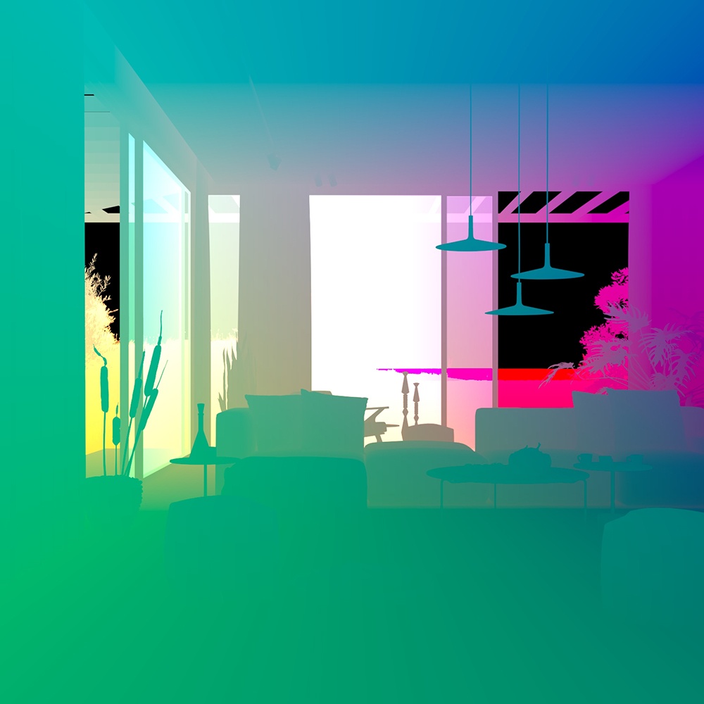
The Point Position pass
(The Sampler Info Render Element was used to create this
in World space with a point multiplier value of 0.001)
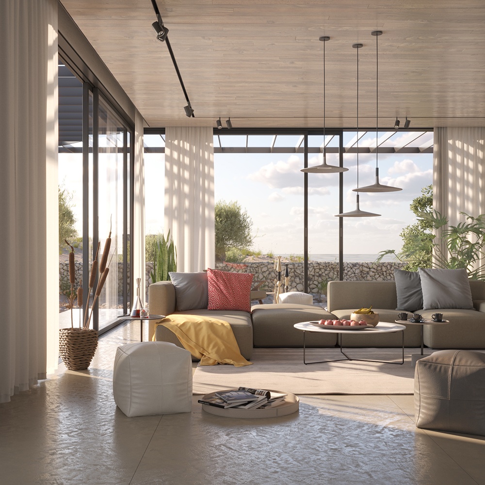
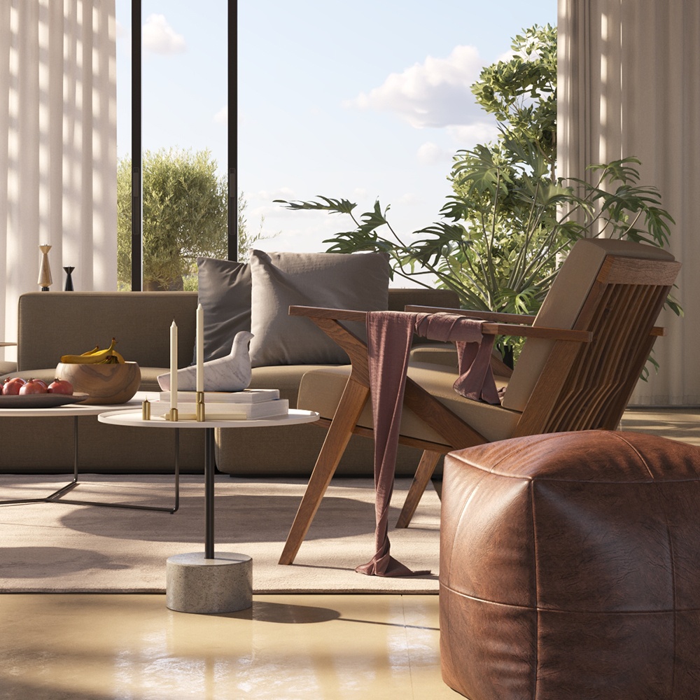
Original Beauty Composite
The resulting relit composite
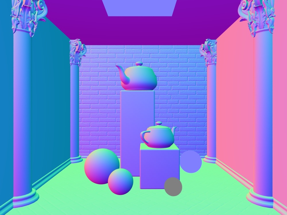
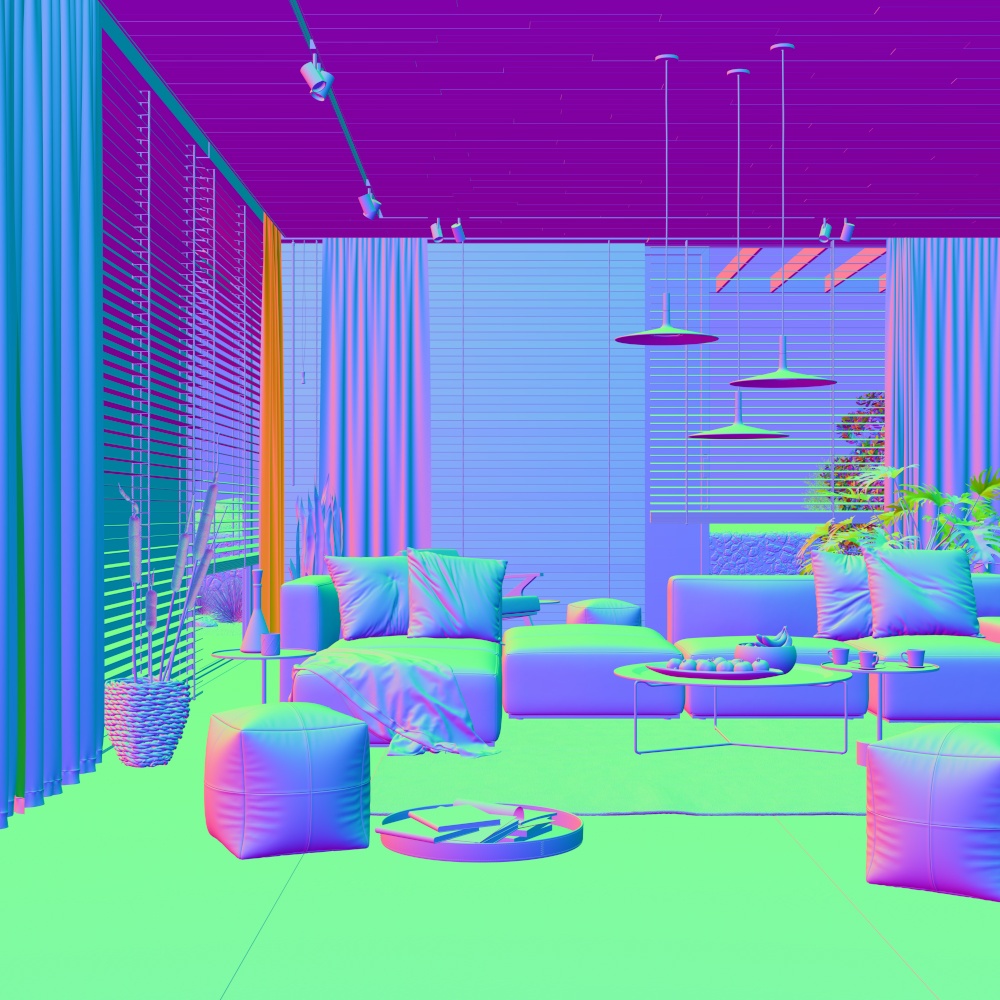
Normals
The Normals Render Element creates a normals image from surface normals in the scene.
The Normals is a render element that stores the camera space normal map using the geometry's surface normals. The Normals Render Element is useful for adjusting lighting in the composite. For example, the red, green and blue channels can be adjusted in compositing software.
Bump maps are not represented in this render element; to include bump maps, use the Bump Normals Render Element. Also compare with the Sampler Info Render Element, which can render a normal map in camera (screen), object, or world space.

Parameters
The Normals Render Element is accessible through the RenderChannelNormals plugin.
- enableDeepOutput - Specifies whether to include this render element in deep images.
- name - (String) The name of the render element containing the denoised image.
- filtering – (Boolean) Whether the image filter is applied to this channel.
Normals Color Generation
The Normals Render Element uses screen space to determine the colors in the render element. With screen space in the camera view:
The X axis runs left-right perpendicular to the camera viewing angle. This is represented in the Red channel of Normals with 1 being left-facing geometry and 0 being right-facing geometry.
The Y runs up-down perpendicular to the viewing angle. This is represented in the Green channel of Normals with 1 being up-facing geometry and 0 being down-facing geometry.
The Z runs forward-back to the viewing angle. This is represented in the Blue channel of Normals with 1 being forward-facing geometry and 0 being back-facing geometry.
Screen space XYZ coordinate system
relationship to camera and RGB colors

Full Normals Render Element
Common Uses
(used mainly for relighting)
The Normals Render Element is useful for changing the appearance of lighting in a scene in a composite without the need for rerendering.
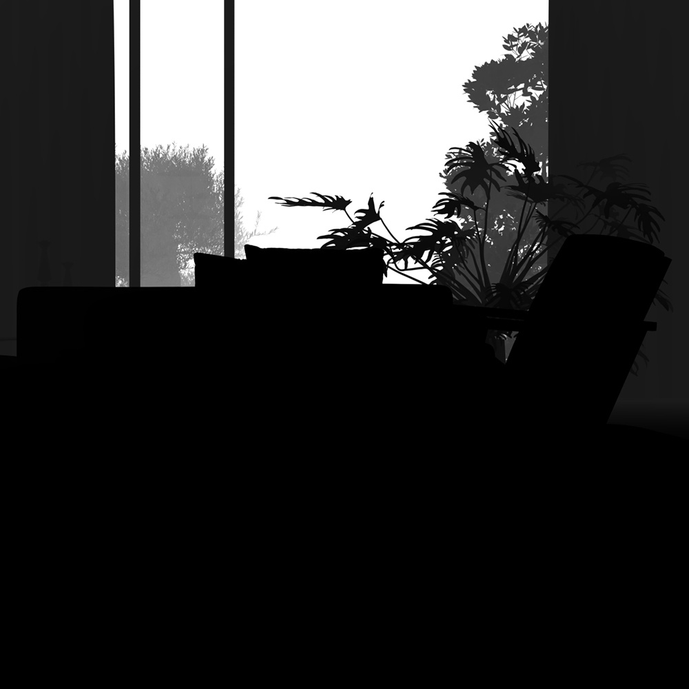
In the example below a relighting workflow is used at a composite level to change the lighting in the scene. Note that it does not create any extra shadowing. This example is exactly the same under the hood as that shown in the Bump Normals Render Element section with the only change being that the Normals Render Element was used here instead of the Bump Normals Render Element.
Normals Render Element
The Point Positon pass
(The Sampler Info Render Element was used to create this
in World space with a point multiplier value of 0.001)

Original Beauty Composite

Resulting re-lit Composite
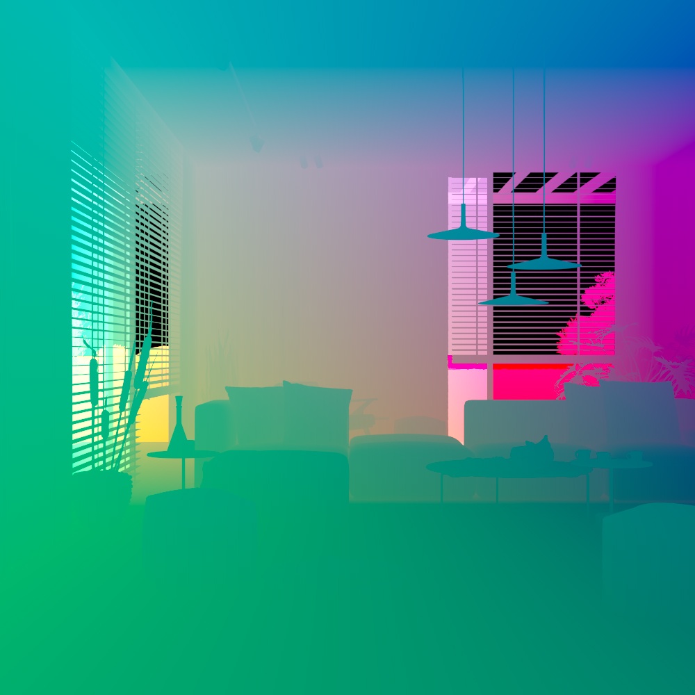
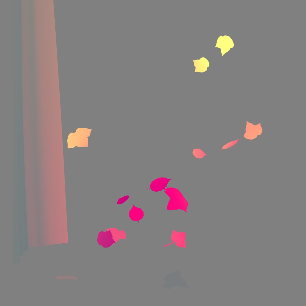
Velocity
The Velocity Render Element is a color or grayscale image that stores velocity information about objects that have moved between the current frame and the next frame.
The Velocity Render Element stores surface velocity for moving objects in the scene with different colors representing different velocities. Each moving object is rendered with a flat color or gradient. It is commonly used to create mattes for adding motion blur in a composite.
The shading in the Velocity Render Element is determined by the degree of motion for each object's pivot point. The object's motion between the current frame and the next frame on the X, Y, and Z axes is mapped to R, G, and B components, with movement along the negative axis as 0 and movement along the positive axis as the maximum value. For example, a white object has moved at the maximum velocity on all three axes in a positive direction, while a black object has moved at the maximum velocity in a negative direction on all three axes. A pale yellow object has moved a great deal on all three axes in the positive direction, but mostly on X and Y, while a dark purple object has moved on the -X and -Z axes. A medium gray color indicates no motion.
Because of the relationship between XYZ motion and RGB colors, the Velocity Render Element can be easily split into R, G, and B components during the compositing process and each direction can handled separately or together to add motion blur.
Parameters
The Velocity Render Element is accessible through the RenderChannelVelocity plugin.
- enableDeepOutput – (Boolean) Specifies whether to include this render element in deep images. The default value is 1.
- name – (String) Displays the name of this render channel. The default value is Velocity.
- clamp_velocity – Sets the limit for max velocity. When enabled, this option limits the max velocity value to 1 for floating point images, 255 for 8-bit images, or 65535 for 16-bit images. This option is useful only when writing to an 8-bit or 16-bit file format.
- max_velocity – (Int) Used to scale the velocity values written to the render element so that they fit within the range specified by the clamp velocity parameter. This is only useful if writing to an 8-bit or 16-bit file format.
- max_velocity_last_frame – (Int) Shows the maximum velocity value that was found while rendering the last image. This is a read-only parameter and can be used as a guide for setting the max velocity parameter.
- ignore_z - (Boolean) Disregards motion along the Z axis.
- filtering - (Boolean) Whether the image filter is applied to this channel.
Suggested Workflow
A common workflow for using this render element is to first locate the frame in the sequence that has the most motion, render the frame with the Velocity Render Element enabled, and then note the max velocity in last frame value, which is displayed in the parameters for this render element. Finally, enter this value (or a slightly larger value) for the max velocity parameter when rendering the entire sequence. This workflow provides the maximum range of colors in the Velocity Render Element for the most flexibility during compositing.
Common Uses
The Velocity Render Element is useful for adding motion blur in post-production at a composite level without the need for rerendering. In the composite shown below, motion blur was added based on the amount by which the color differs from medium gray. The feathers that were given a pale yellow color in the render element are the most blurred.
Velocity Render Element

Original Beauty Composite

Beauty Composite with motion blur added using the Velocity Render Element
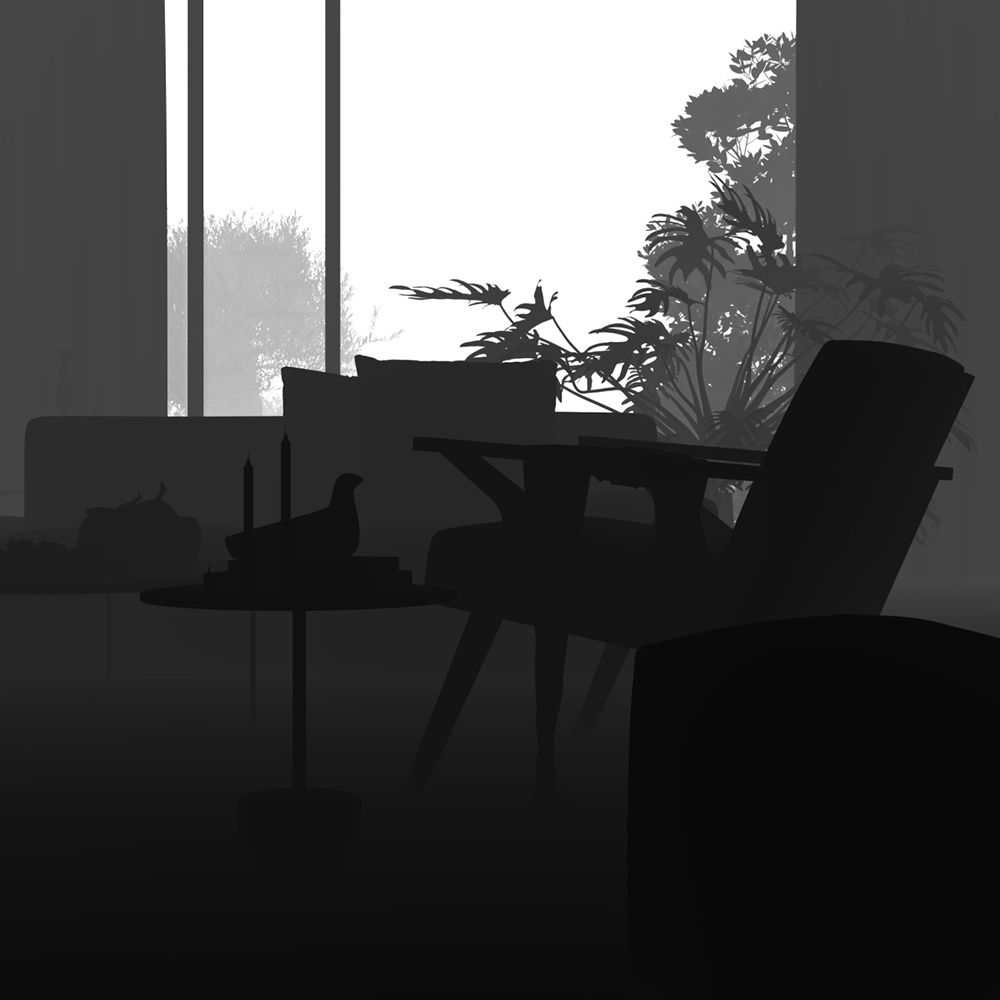
Z-Depth
The Z-Depth Render Element is a grayscale image that renders each pixel based on its distance from the camera in the view.
The Z-Depth Render Element provides information about each object's distance from the camera in the current view. Each pixel representing the object is evaluated for distance individually; different pixels for the same object can have different grayscale values. In this render element, objects (or portions of objects) closest to the camera appear as white while those furthest away appear black. Objects between the furthest and nearest points are rendered in varying shades of gray. The lighter the gray, the closer an object pixel is to the camera.
The most common usage of the Z-Depth Render Element is as a control for depth of field in the composite. Depth of field can be challenging to do correctly within the host application, requiring many tweaks and re-renders; using the Z-Depth Render Element in a composite is usually much faster, and allows easier and faster adjustment than trying to get it exactly right within the render from the host application.

Parameters
The Z-Depth Render Element is accessible through the RenderChannelZDepth plugin.
- enableDeepOutput – (Boolean) Specifies whether to include this render element in deep images. The default value is 1.
- name – (String) Displays the name of this render channel. The default value is ZDepth.
- depth_from_camera – (Boolean) Specifies whether to use to camera clip boundaries as the minimum and maximum Z-Depth distance. Enabling this option disables the zdepth black (zdepth min) and zdepth white (zdepth max) parameters.
- depth_black – (Int) Objects up to this distance from the camera render as white. This option is available only when depth_from_camera is disabled.
- depth_white – (Int) Objects further than this distance from the camera render as black. This option is available only when depth_from_camera is disabled.
- depth_clamp – (Boolean) Clamps the Z-Depth colors to a linear 0-1 range.
- filtering – (Boolean) Specifies whether the image filter is applied to this channel.
- depth_invert – (Boolean) If true, zdepth is inverted.
- force_infinity_black – (Boolean) Sets infinite depth value to 0.0.
- dont_filter_env – (Boolean) Don't filter object edges against the environment.
Z-Depth Minimum and Maximum
The Z-Depth Render Element parameters for minimum and maximum depth, zdepth min and zdepth max, can be set to various values to provide different ranges of depth in the render element. In these examples, clamp zdepth is enabled and invert zdepth is disabled.
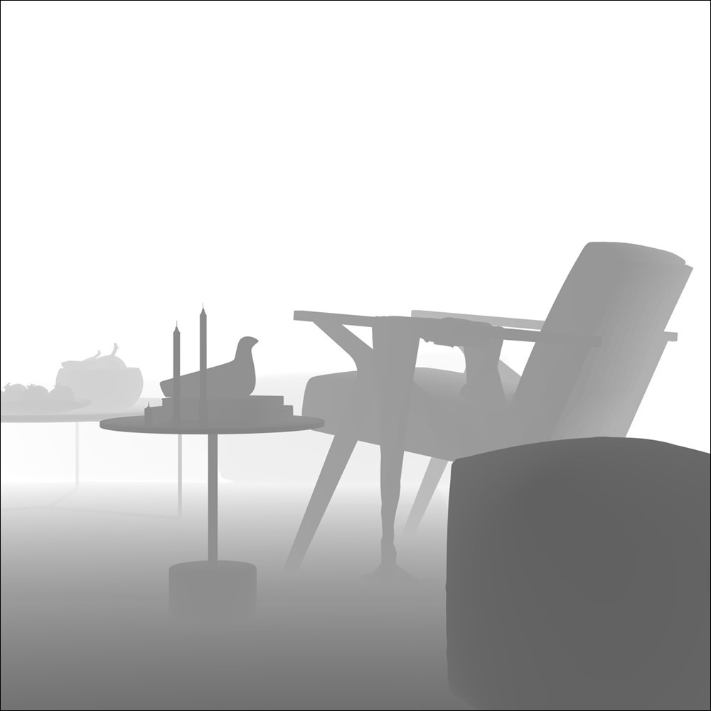
Zdepth min = 0cm, Zdepth max = 600cm
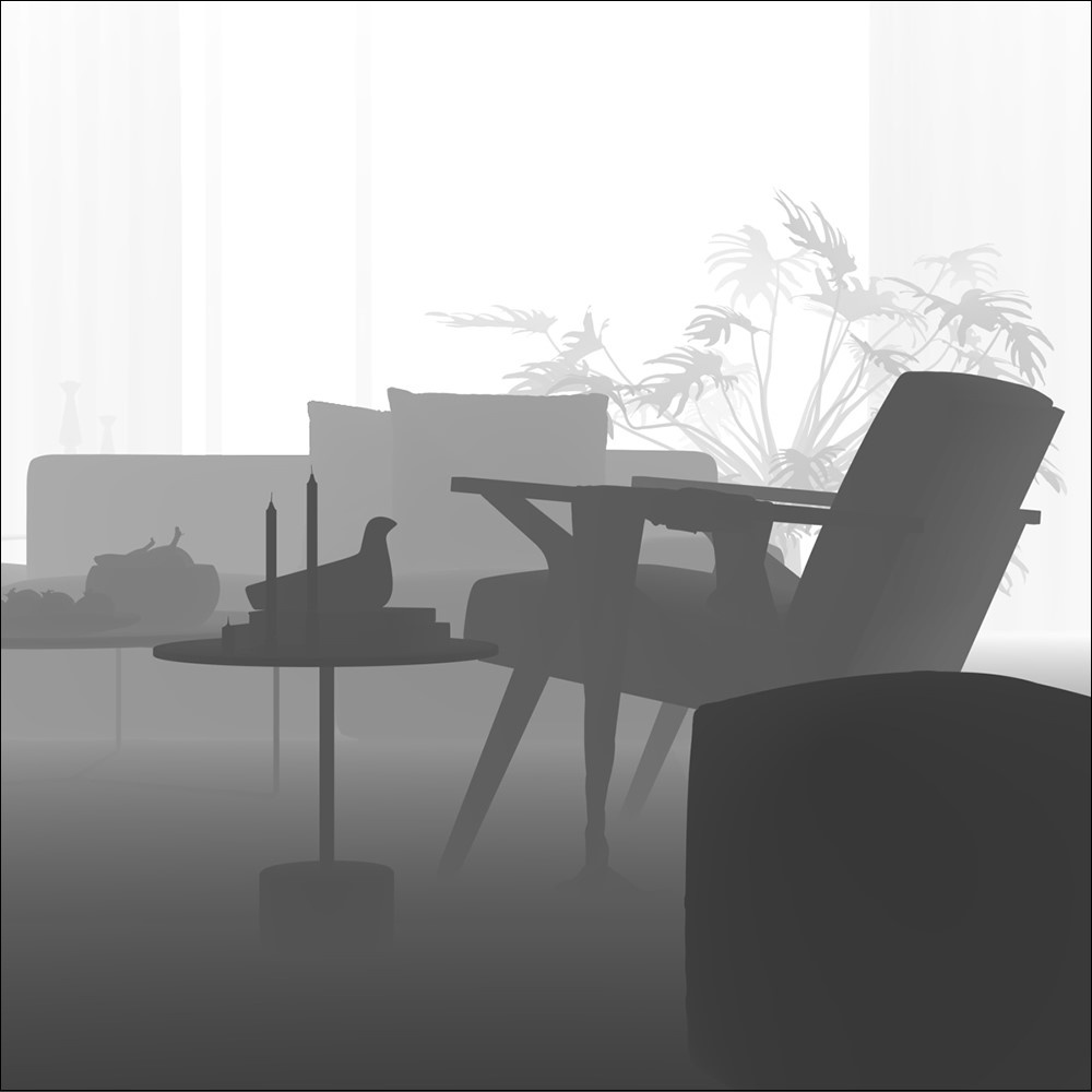
Zdepth min = 0cm, Zdepth max = 1000cm
Zdepth min = 0cm, Zdepth max = 3500cm
Zdepth min = 400cm, Zdepth max = 3500cm
Zdepth min = 600cm, Zdepth max = 3500cm
Common Uses
The Z-Depth Render Element is useful for adding depth of field to the final image in post-production using a compositing application without the need for rerendering. It can also be used to create basic fog by overlaying it on the composite with Add mode or Screen mode, with color correction as needed.
Depth of field applied to composite using Z-Depth Render Element
Original Beauty Composite
Basic fog applied to composite using Z-Depth Render Element