In this chapter, we cover the utility render elements. Most of them are implemented using the RenderChannelColor plugin, unless stated otherwise.
Overview
The Utility Render Elements are a group of render elements that are generated for use in a number of different compositing and image manipulation needs. They have a wide variety of uses both inside and outside of the compositing process.
Some of these render elements are also useful for optimizing renders and troubleshooting issues and aren't necessarily used as images in actual compositing.
Utility Render Elements List:
- Coverage (VRayCoverage) – For each pixel, the final values for the render element are taken from the object that makes the largest contribution to that pixel. Type: RenderChannelCoverage
- Distributed rendering ID (VRayDRBucket) - Creates an image of buckets as colored rectangles, with the name of the machine that rendered the bucket displayed on each bucket. Type: RenderChannelDRBucket
- Extra texture (VRayExtraTex) - Renders the entire scene with one texture mapped on all objects. Type: RenderChannelExtraTex
- Illuminance (VRayIlluminance) - Displays the illumination in each part of the scene in a similar way to the Light Meter | VRayLightMeter helper.
- Sample rate (VRaySampleRate) - Shows where the pixel brightness is directly proportional to the number of samples taken at this pixel. Type: RenderChannelColor
- Sampler info (VRaySamplerInfo) - Provides information about various aspects of the shaded points such as position, normal, bump normal, reflection/refraction vectors and UVW coordinates. Can be used for world position passes or normal passes.
- V-Ray Render Options (VRayOptionRE) - A special render element that controls some internal settings for V-Ray that are otherwise unaccessible; it does not generate any actual data. Type: SettingsRenderChannels
- V-Ray Denoiser (VRayDenoiser) - Takes an existing render and applies a denoising operation to smooth out areas of noise in the render. Type: RenderChannelDenoiser
Examples
Distributed Rendering ID
Extra Texture
Illuminance

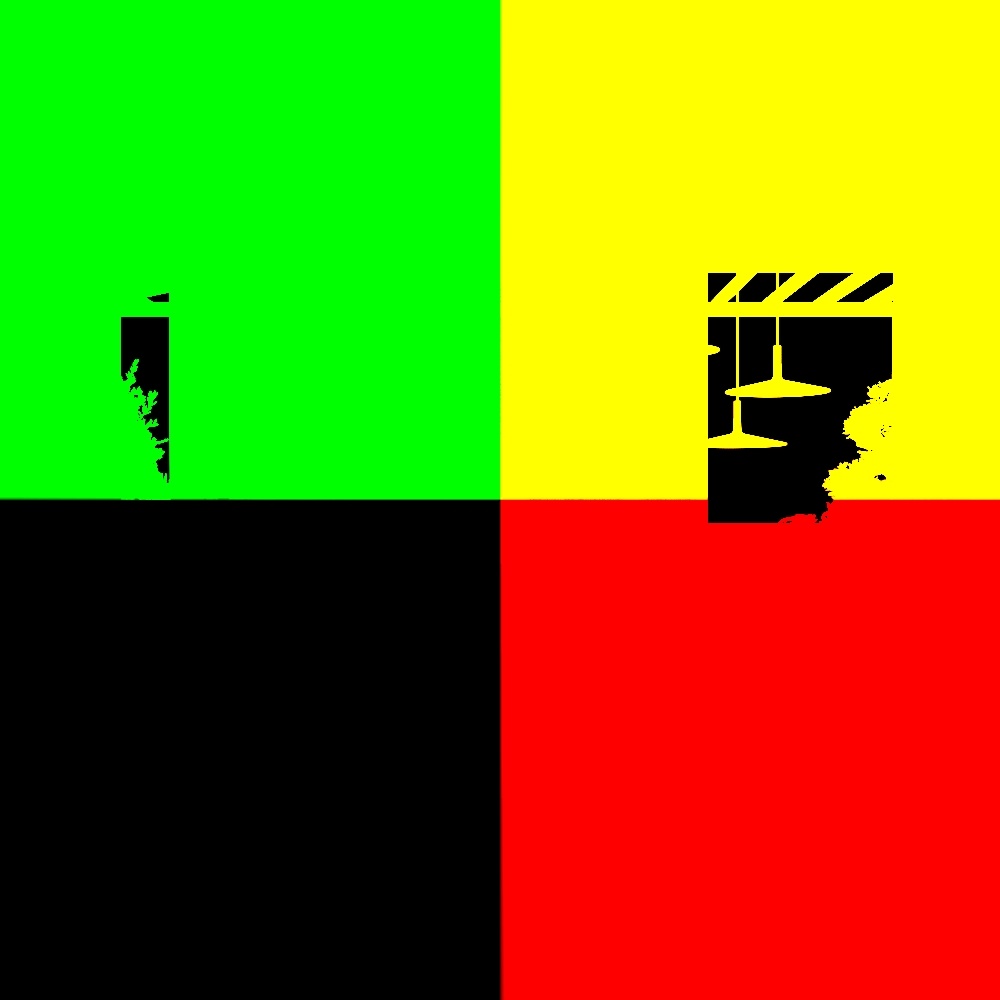
Material Select
Sample Rate
Coverage
The Coverage Render Element holds anti-aliasing data based on the Render ID Render Element.
When the Coverage Render Element is multiplied by the Render ID Render Element in compositing, it adds anti-aliasing to the Render ID channel, providing a quick object mask.

Parameters
The Coverage Render Element is accessible through the RenderChannelCoverage plugin.
- enableDeepOutput – (Boolean) Specifies whether to include this render element in deep images. The default value is 1.
- name – (String) Displays the name of this render channel. The default value is DR.
Distributed rendering ID
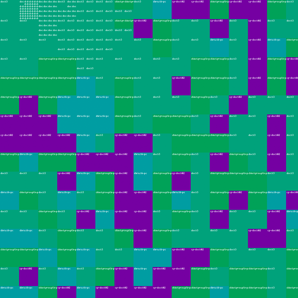
The Distributed rendering ID Render Element shows the name of the rendering machine that rendered any particular bucket when distributed rendering is used.
The Distributed rendering ID Render Element renders an image with each bucket shown in a different color, and a short text on each bucket naming the machine that rendered it. A bucket is a region of an image that is being rendered. The render setup must be set to use the Bucket image sampler, which divides the rendering process into render buckets. This render element is useful for assessing machine performance or for troubleshooting a distributed rendering process.
Parameters
The Distributed rendering ID Render Element is accessible through the RenderChannelDRBucket plugin
- enableDeepOutput – (Boolean) Specifies whether to include this render element in deep images. The default value is 1.
- name – (String) Displays the name of this render channel. The default value is DR.
- text_alignment – (Int) Sets the alignment of the machine name that displays on each bucket. (1 - Right, 2 - Left, 3 - Wrap)
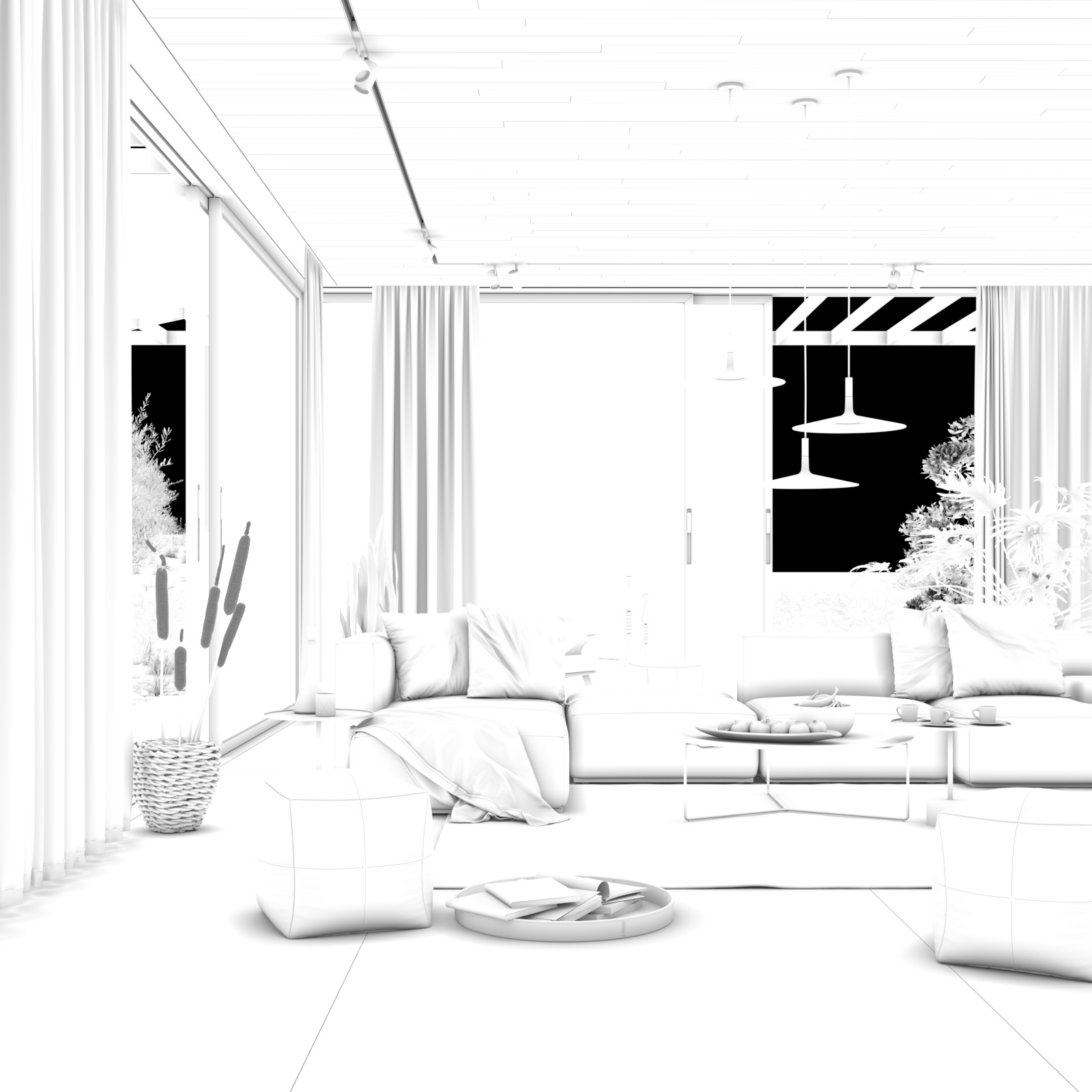
Extra Texture
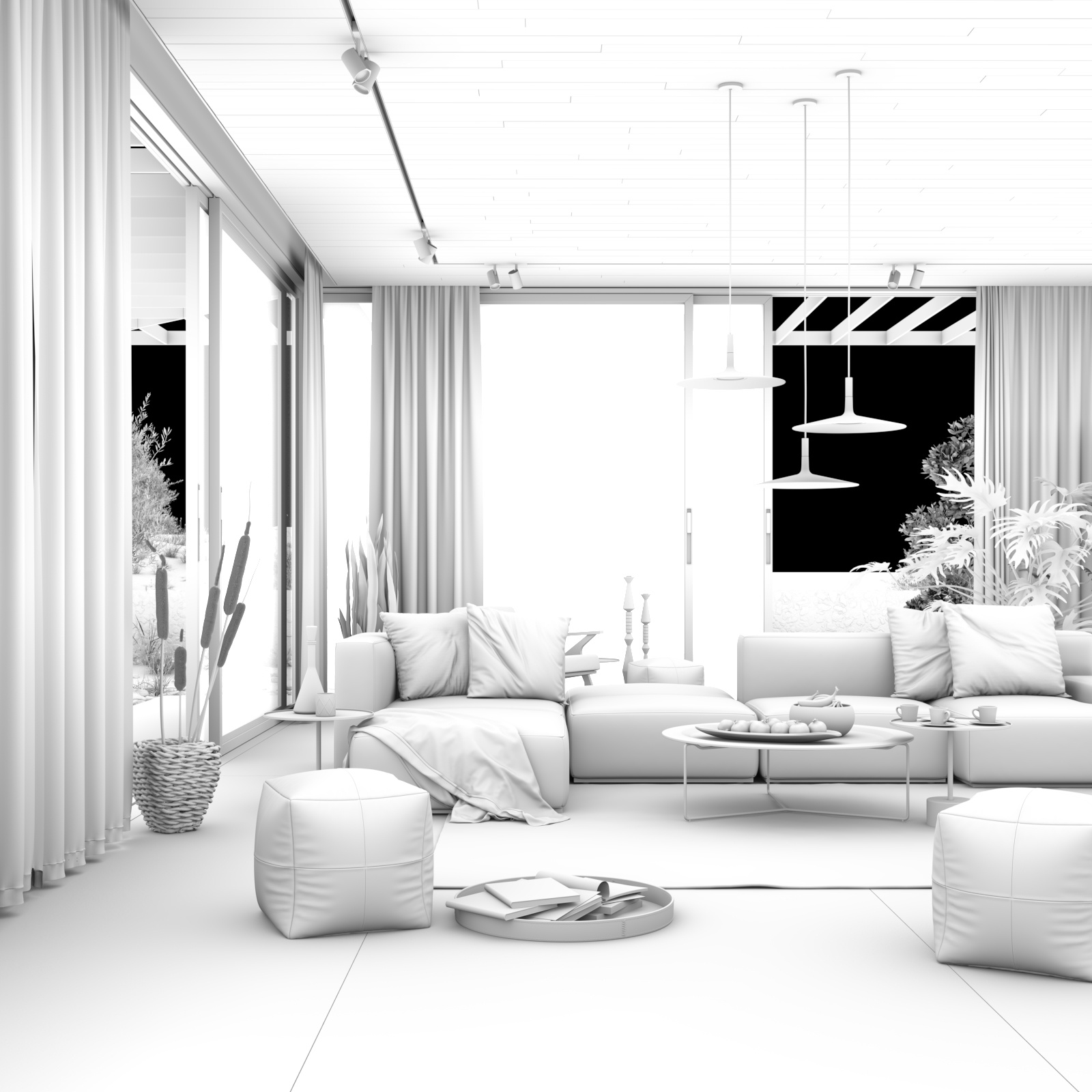
The Extra Texture Render Element renders the entire scene with one texture mapped onto all objects in the scene.
The Extra Texture Render Element shows the rendered image with a single texture applied to all objects in the scene. The texture applied to the scene can be a bitmap or a procedural texture such as TexDirt or TexCurvature.
A common use for Extra Tex is to use TexDirt as the texture, which creates an ambient occlusion element for use in the composite. In this way, ambient occlusion can be controlled separately during the compositing process.
While you can obtain a result similar to the Extra Tex render element by applying the same texture to all objects in the scene and rendering as usual, such an approach requires additional time spent on reverting to actual materials, saving different versions of the scene, etc. The Extra Tex render element provides you with a quick and easy way to render the scene with a single texture without the extra work.
Extra texture with applied texture
Extra texture with applied TexDirt
Extra texture with applied TexFalloff
Parameters
The Extra Texture Render Element is accessible through the RenderChannelExtraTex plugin.
enableDeepOutput – (Boolean) Specifies whether to include this render element in deep images. The default value is 1.
name – (String) Displays the name of this render channel. The default value is ExtraTexChannel.
- consider_for_aa – (Boolean) When enabled, antialiasing is considered where possible.
- affect_matte_objects – (Boolean) Sets whether to include matte objects when generating the render element. A matte object is an object that has been assigned a Wrapper Material with the Matte surface option enabled.
- texmap – The texture to apply to the scene.
- filtering – (Boolean)Specifies whether the image filter is applied to this channel.
- exclude_list – List of objects that can be included or excluded from receiving the texture.
- exclude_list_as_inclusive_set – (Boolean) True to apply extra texture only to objects in exclude_list; false to apply extra texture to all objects out of exclude_list.
- force_32_bit_output – (Boolean) Forces 32-bit float output even in half-float images.
- force_lossless_compression – (Boolean) Forces lossless compression for this channel when DWAA/DWAB compression is used.
- denoise – (Boolean) True to denoise the channel; false otherwise.
- background – The texture that is used as background.
Common Uses
The Extra Texture Render Element is useful for changing the appearance of a render in a compositing or image editing software. The example below uses a VRayDirt texture with its radius parameter set to 300cm and subdivs set to 6.
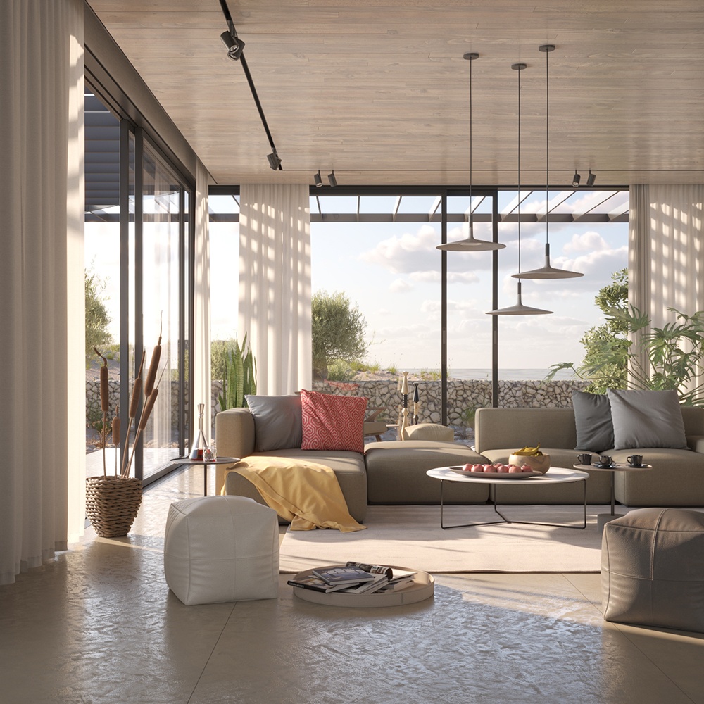
Beauty Render Element
Extra Tex element with VRayDirt texture with a radius of 10cm
Extra Tex element with VRayDirt texture multiplied over the Beauty
Beauty Render Element
Extra Tex element with VRayDirt texture with a radius of 100cm
Extra Tex element with VRayDirt texture multiplied over the Beauty
Illuminance
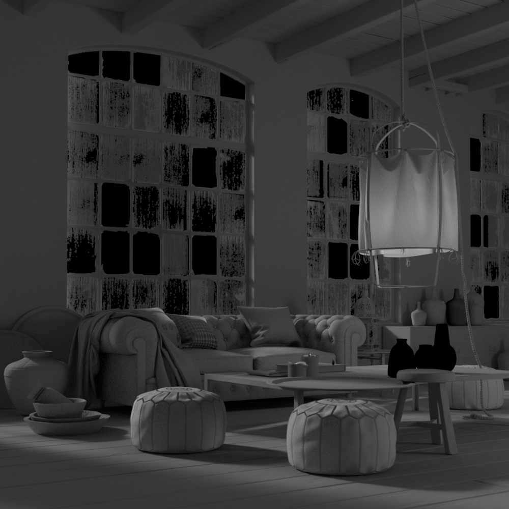
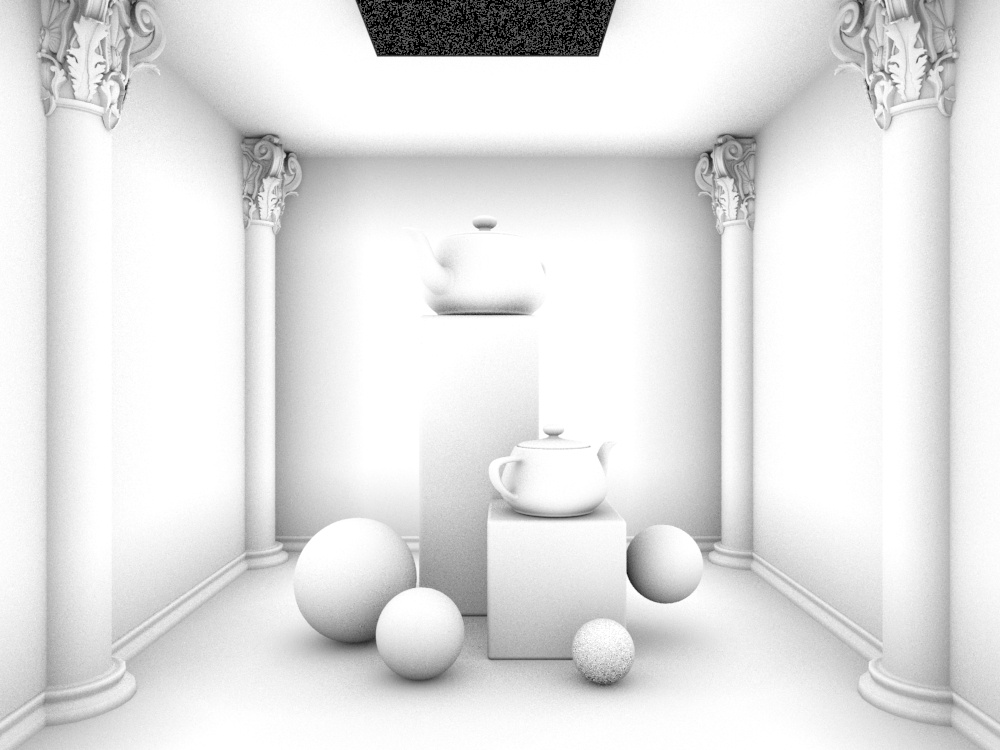
The Illuminance Render Element is a grayscale or color image that displays the illumination in each part of the scene.
The Illuminance Render Element displays the illumination in each part of the scene in a similar way to the VRayLightMeter helper. The colors in the render element are scaled to show the maximum and minimum light in the scene as a range from white to black. The maximum amount of illumination is represented as pure white while the minimum is pure black. How the shades of gray or color are represented in between is set by the mode parameter.
This render element is useful for adjusting overall levels of brightness in the composite.

Examples
Illuminance set to Linear mode
Illuminance set to False colors mode
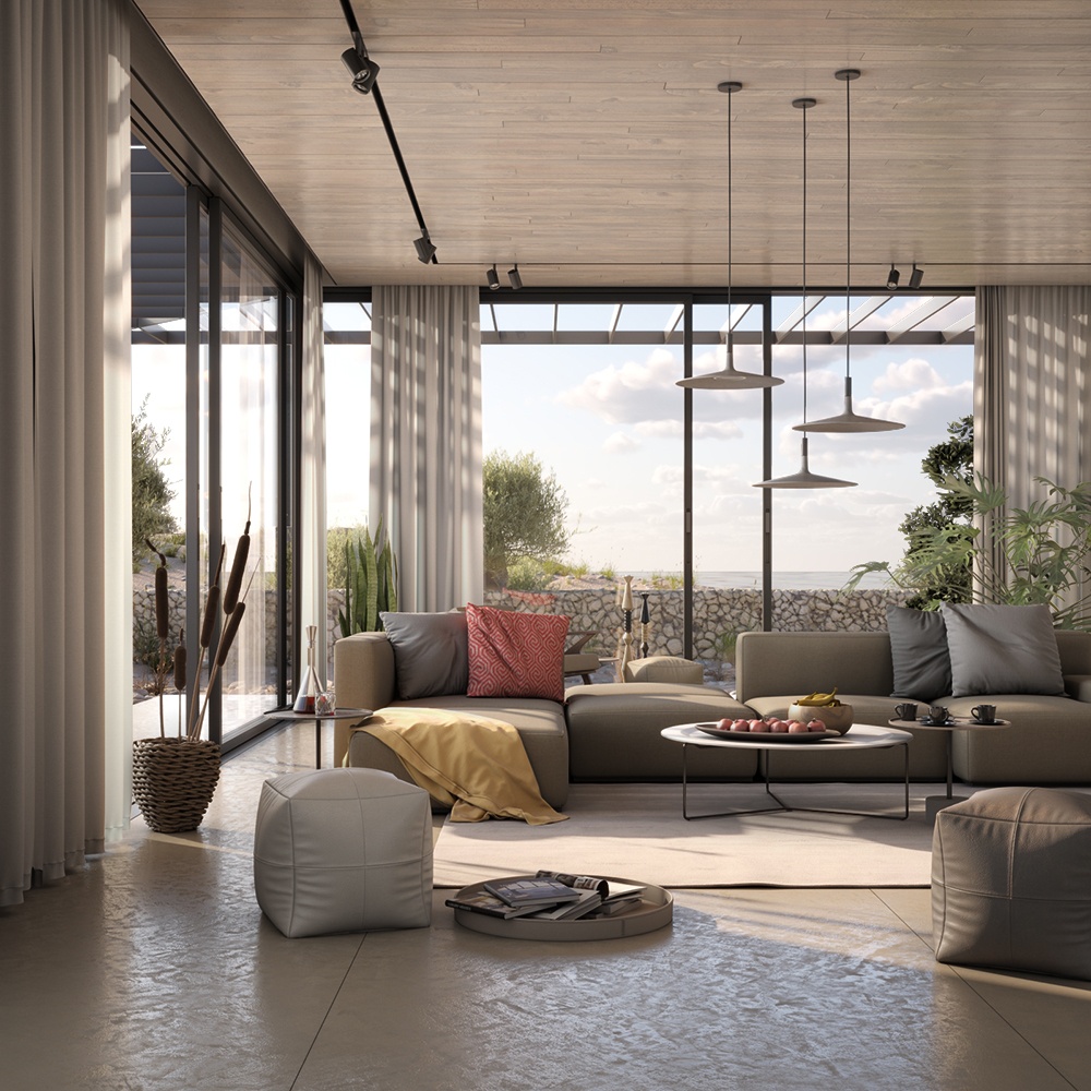
Sample Rate
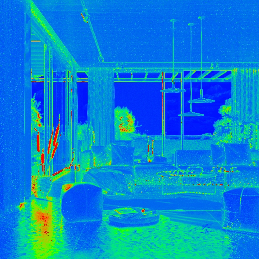
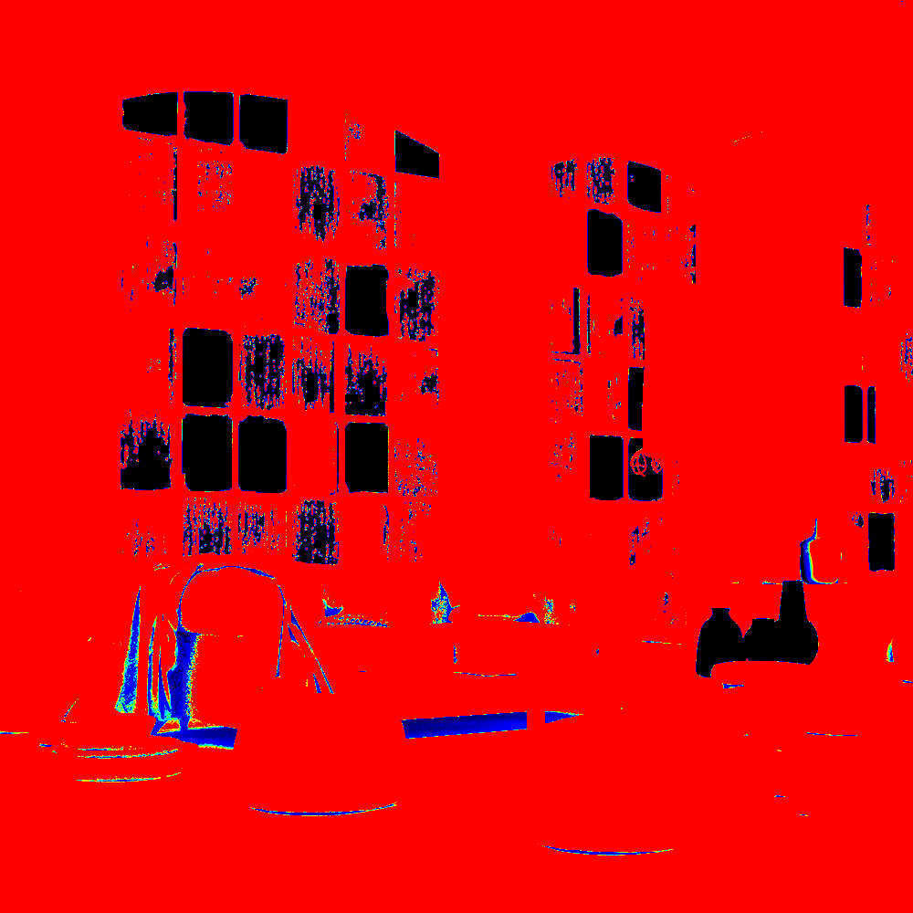
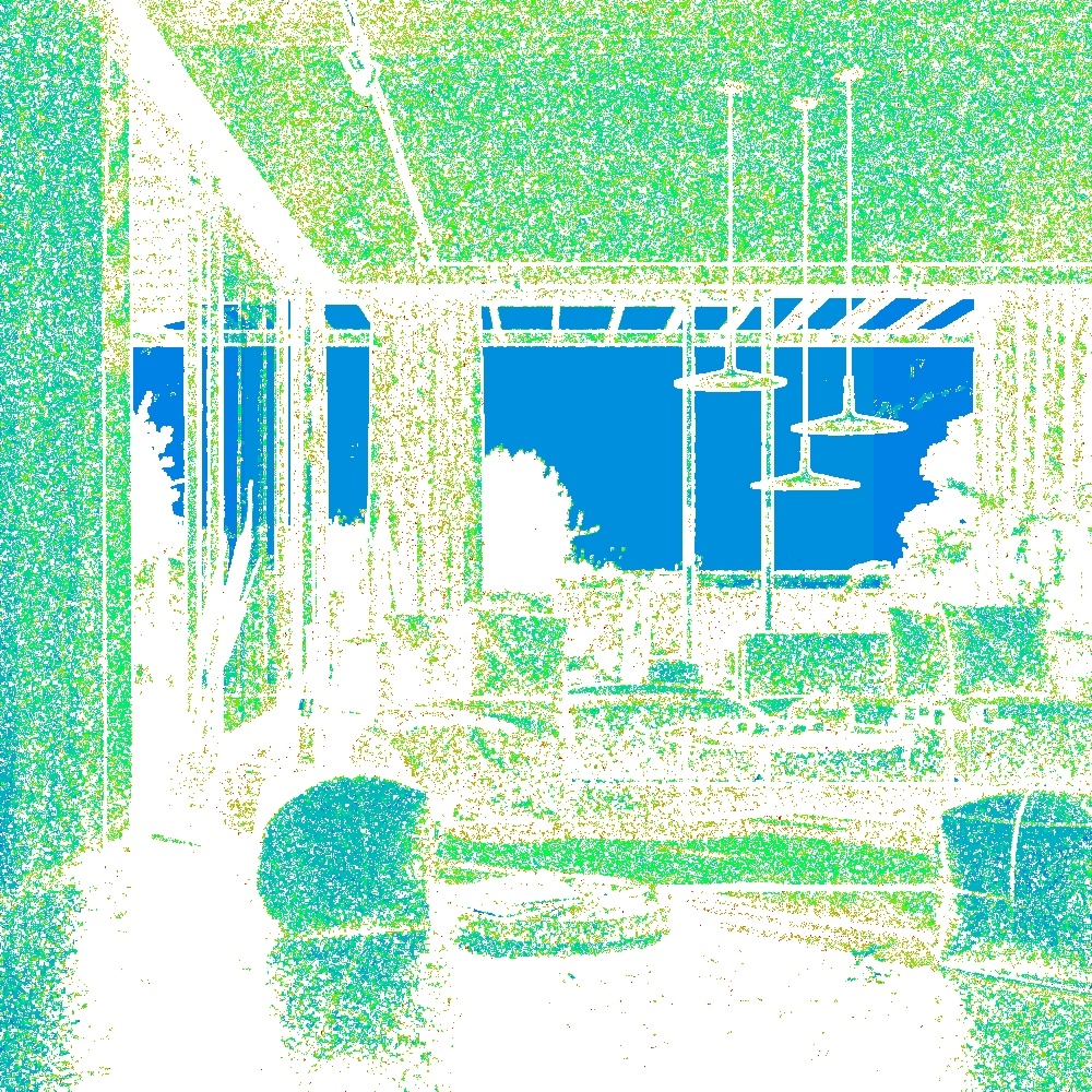
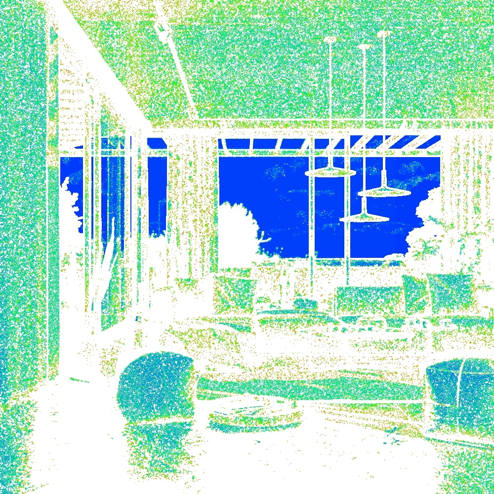
The Sample Rate Render Element displays the work being done by the image sampler as a red, green, and blue image.
The Sample Rate Render Element displays the work being done on the image as it is rendering, and shows the job done when the render completes.
A color is assigned to each pixel according to how many primary samples are being taken by the Image Sampler:
- The Blue channel contains the areas which reached the desired image quality with few primary samples.
- The Green channel shows areas which required more antialiasing (AA) samples to clean up than the Blue areas, but managed to achieve the Noise Threshold within the number of AA rays used.
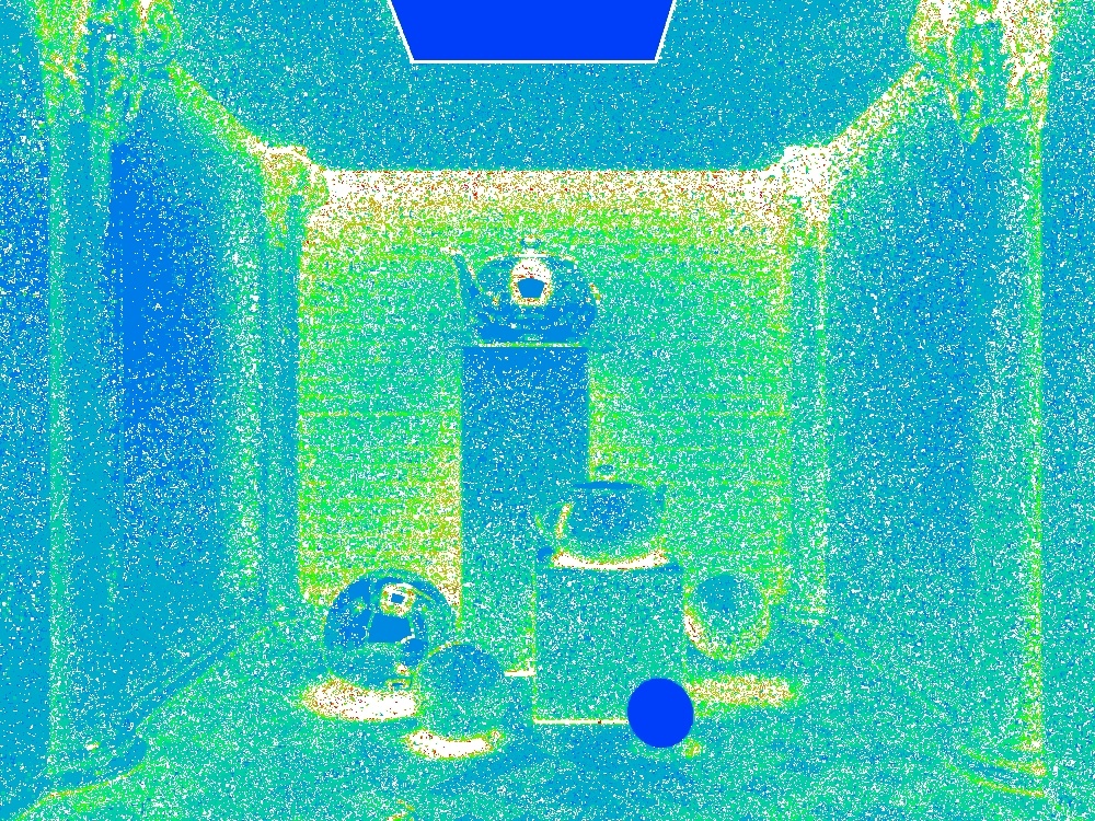
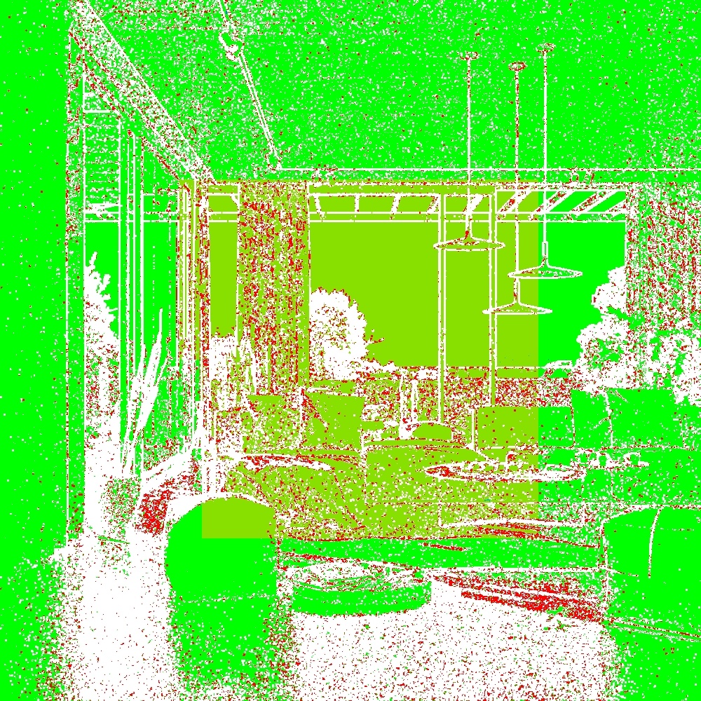
- The Red channel contains the parts of the image which didn't make it to the desired quality threshold, as they reached the maximum amount of AA rays before reaching the Noise Threshold.
- If the Image Sampler type is Progressive, the White areas represent the areas the sampler is currently working on, as they were found to not satisfy the Noise Threshold as of yet.
The way to ensure a render is correctly computed is to minimize the amount of red color in this render element. Raising secondary sampling through any means reduces the primary sampling work in the corresponding areas, effectively moving red areas into green ones, and green ones into blue ones. Lowering secondary samples per pixel does the opposite, potentially leading to more red areas. The suggested way to minimize the red color and optimize render times to increase the Max AA Subdivs value (if the previous render was still noisy), or increase the Noise Threshold value (if the previous render was clean, but took too long to complete).
Note that some specific image features, like high-frequency detail often found in fur and hair, or high-contrast zones, will likely always try to reach the maximum sampling, so some red will appear there. This is perfectly normal and doesn't slow down the rest of the rendering while ensuring the problematic parts of the image will clean up as per the user's settings.
Common Uses
Sample Rate can be used with both the Bucket and Progressive image samplers.
Bucket Image Sampler
The Sample Rate Render Element is useful for fine-tuning render settings using a "red is bad" rule.
Below is a scene with minimal red in the Sample Rate Render Element, indicating that the sampler had a high enough Max Subdivs value to hit the desired noise level.

Render time = 11m 39s, Max Subdivs = 24, Noise Threshold = 0.01, Min shading rate = 6
The image sampler is mostly able to reach the noise threshold using the subdivisions allotted.
In the next image, the sampler did not have a high enough Max Subdivs value to hit the desired noise level. The high amount of red shows that the image sampler cut off sampling before the image hit the desired noise level. Noise can be decreased by increasing the Max Subdivs parameter to allow the image sampler to reach the desired noise level.


Render time = 6m 17s, Max Subdivs = 8, Noise Threshold = 0.01, Min shading rate = 6
The Image sampler is mostly not able to reach the specified noise threshold.
The primary samples can be allocated to the complex areas of the image by increasing both the Max Subdivs and the Noise Threshold values. This way, V-Ray has available enough primary samples to lower the noise of the complex areas in exchange for an overall slight increase in noise, while still keeping the render times down.


Render time = 5m 37s, Max Subdivs = 12, Noise Threshold = 0.02, Min shading rate = 6
Sample Rate Render Element with not enough max subdivs.
The Image sampler is mostly not able to reach the specified noise threshold.
Alternatively, the image sampler can allocate primary and secondary samples by changing the Min shading rate value.
For this scene, increasing the Min shading rate allows the sampler more secondary samples to focus on cleaning the lighting, GI, reflections and refractions. In exchange, some of the detailed fur and high contrast areas are a bit noisier as there are not enough primary samples taken for those areas.


Render time = 8m 38s, Max Subdivs = 8, Noise Threshold = 0.01, Min shading rate = 20
Sample Rate Render Element with not enough Max Subdivs.
Less primary samples are needed to hit the desired noise level, since more secondary samples are taken.
Progressive Image Sampler
The Progressive sampler uses the same algorithm as the Bucket sampler. The main difference is that the maximum samples increase as the sampler finishes each pass.
11 passes
Very few samples are given to complex areas of the image
36 passes
Samples start to focus on difficult areas.
200 passes
Many samples start to collect only when needed.
White areas are the primary target now.
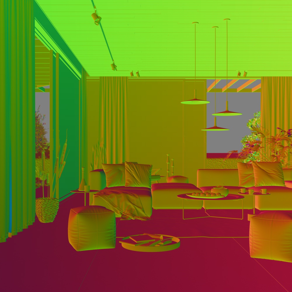
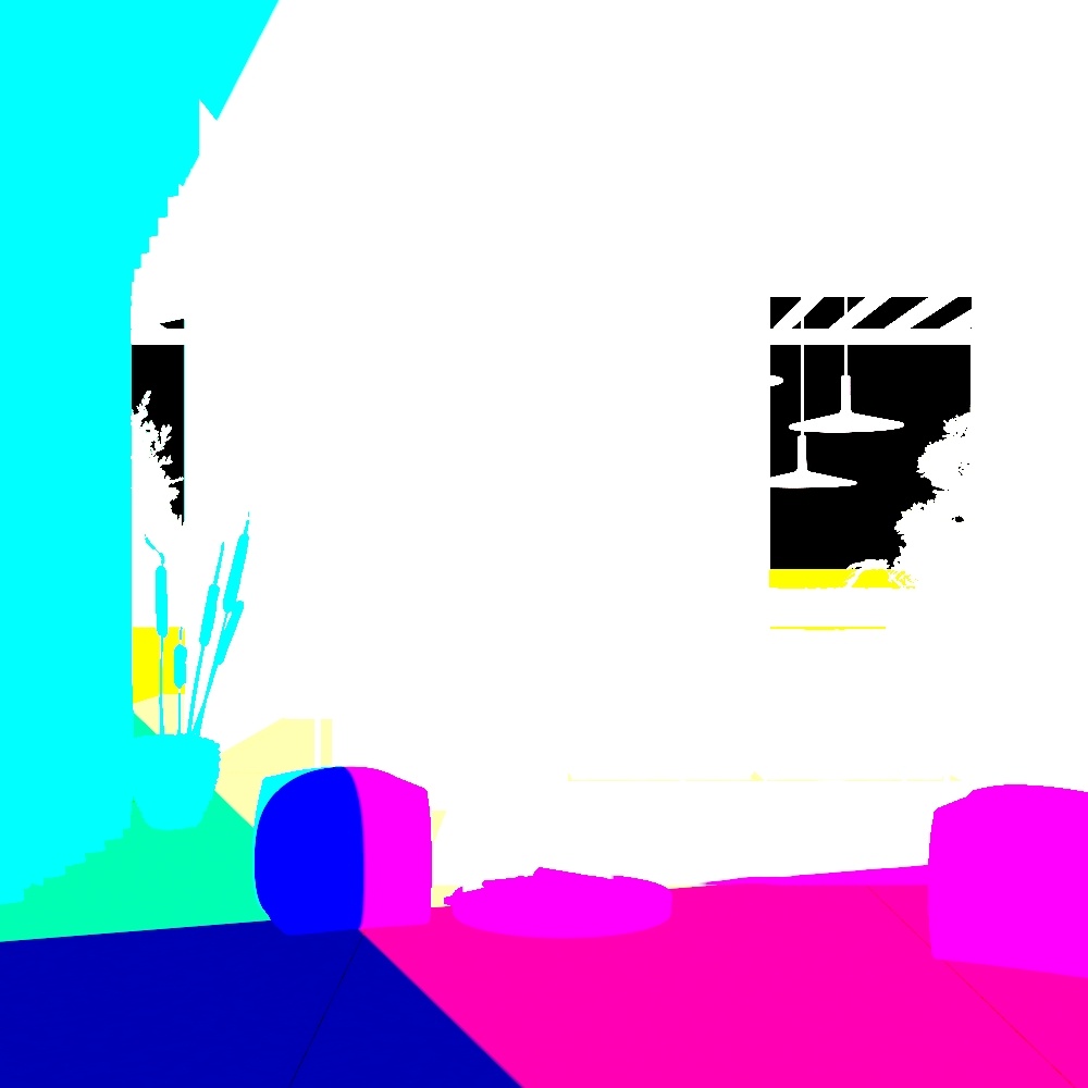
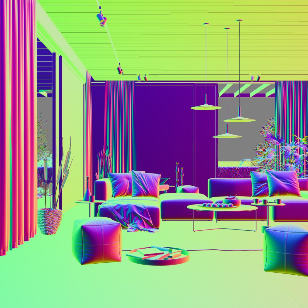
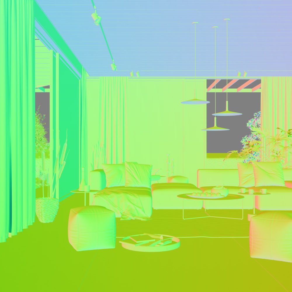
Sampler info
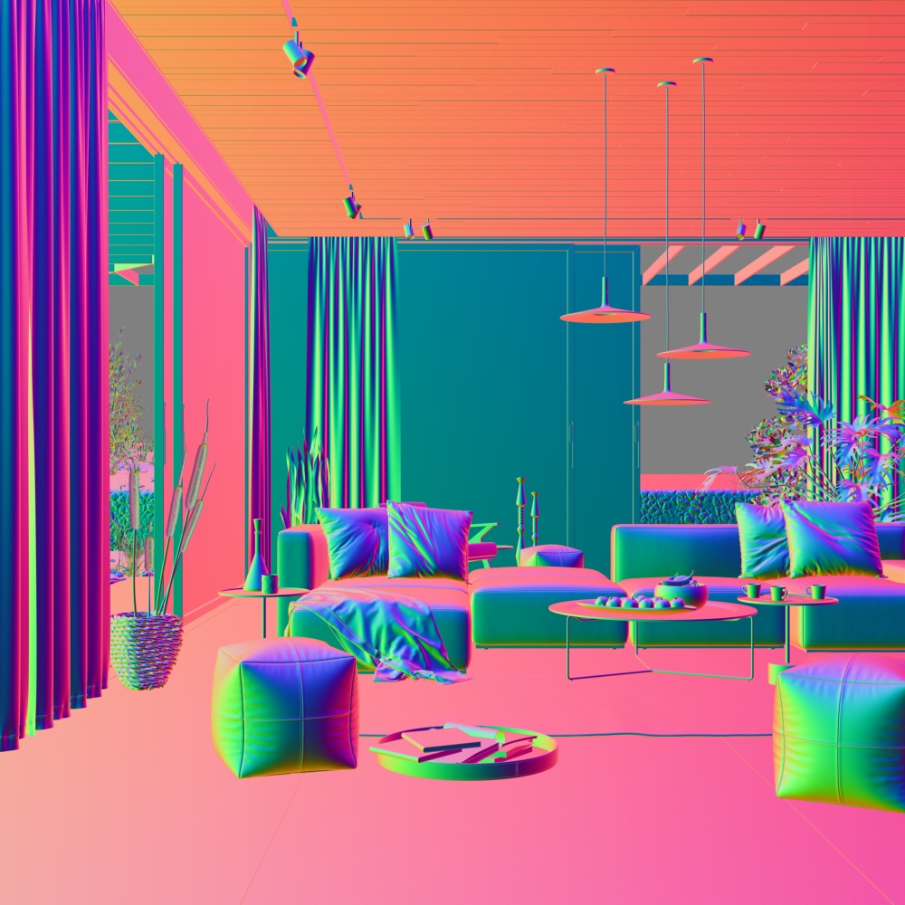
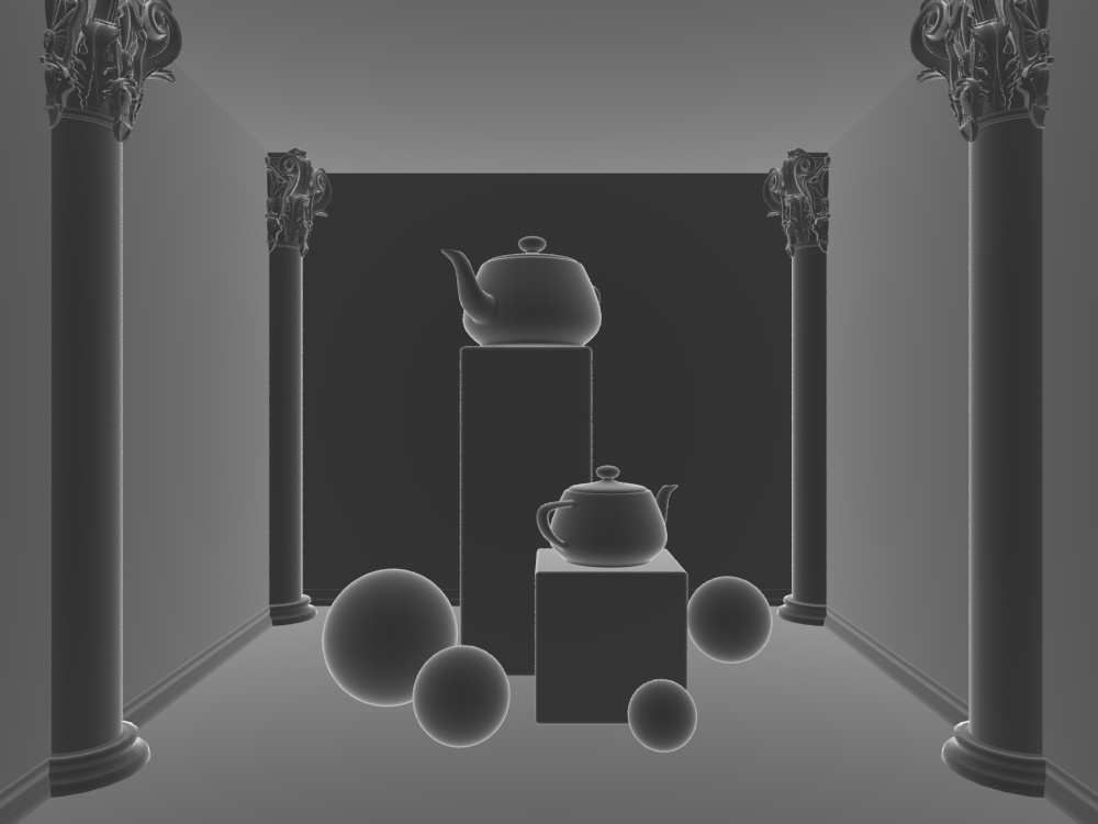
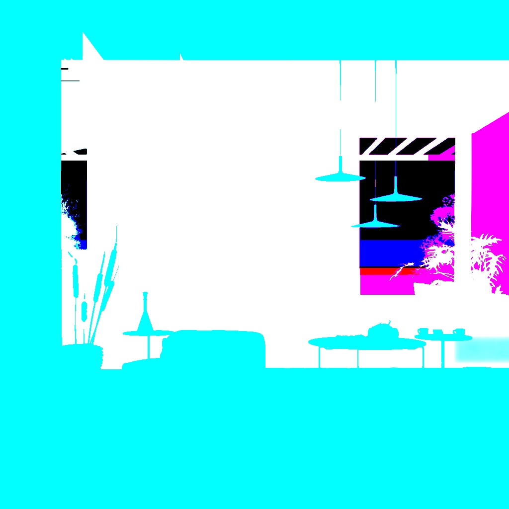
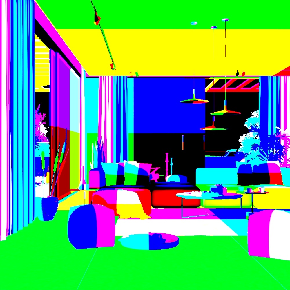
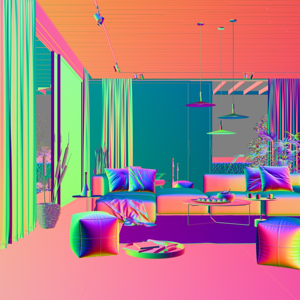
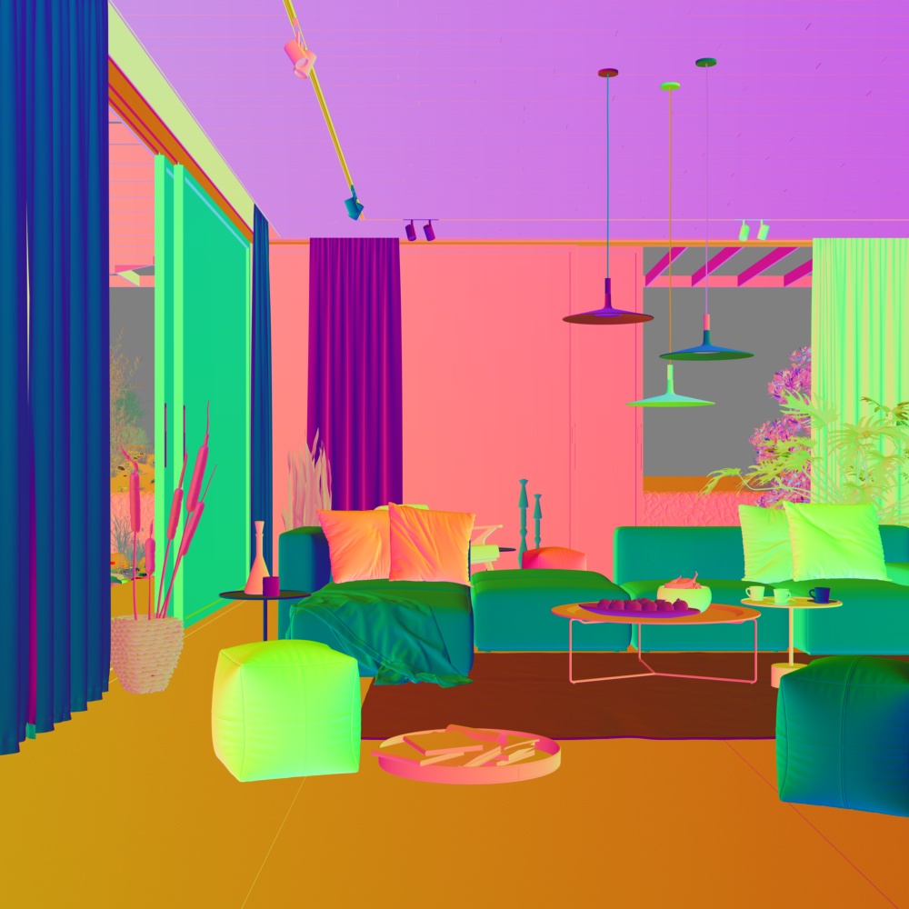
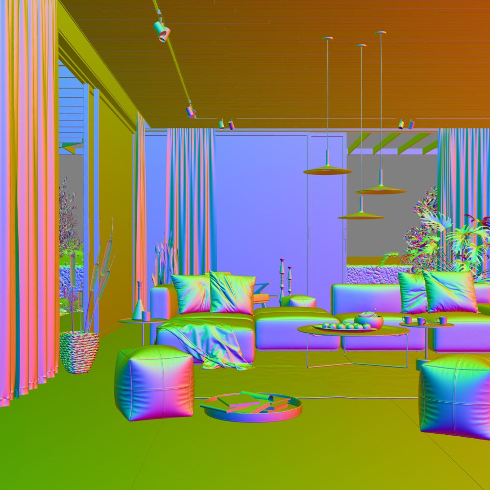
The Sampler Info Render Element is a color image that provides information about the scene, with the choice to show any of various aspects as color blocks.
The Sampler Info Render Element provides information about various aspects of the shaded points such as position, normal, bump normal, reflection/refraction vectors and UVW coordinates. This render element can be used either for world position passes or normal passes. It extracts particular information about the scene, converting the gathered information into RGB data for use in compositing.
Common Uses
The VRaySamplerInfoTex texture extracts particular information about the scene. It then converts the gathered information into RGB data that can be used for compositing.
Sampler Info Render Element with Type set to Point (world space)
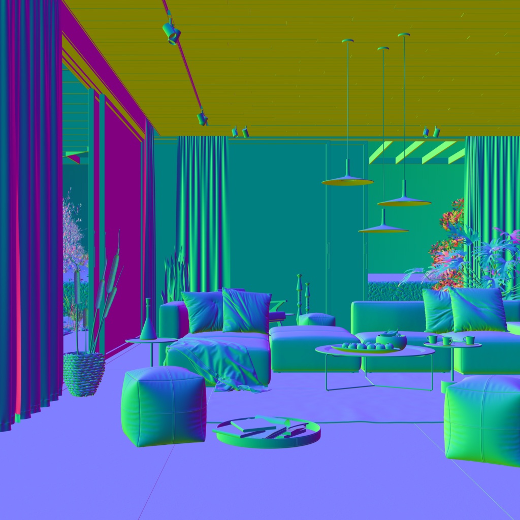
Sampler Info Render Element with Type set to Normal vector (world space)
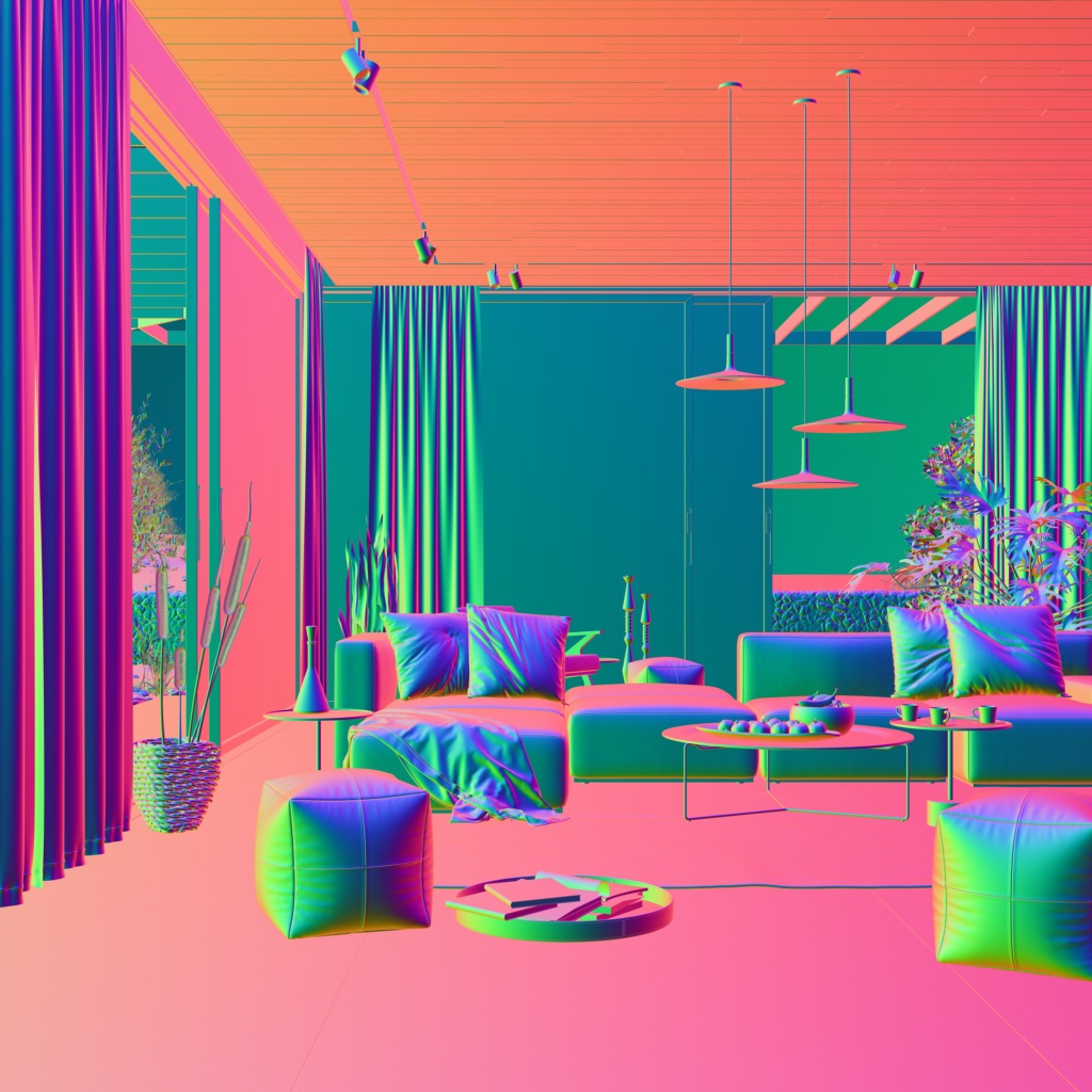
Sampler Info Render Element with Type set to Reflection vector (world space)

Sampler Info Render Element with Type set to Refraction vector (world space)
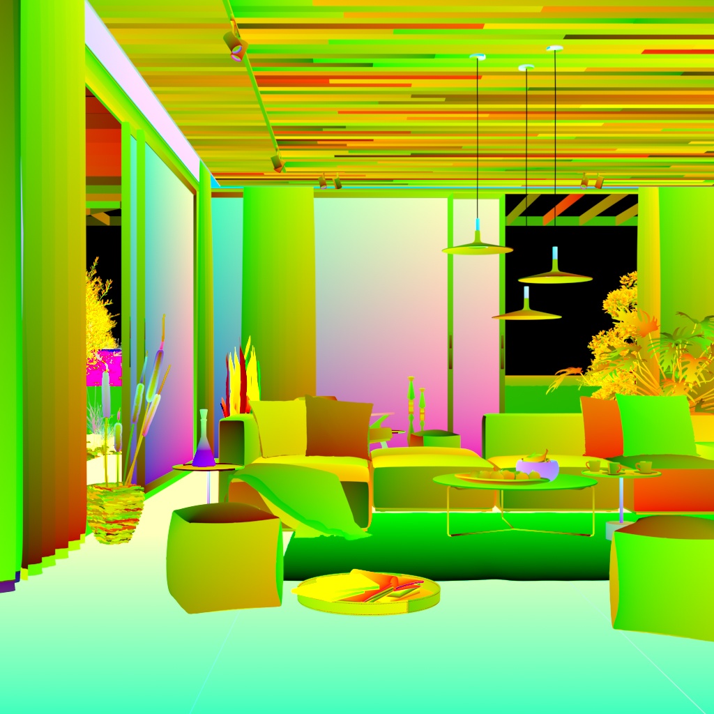
Sampler Info Render Element with Type set to UVW coordinates
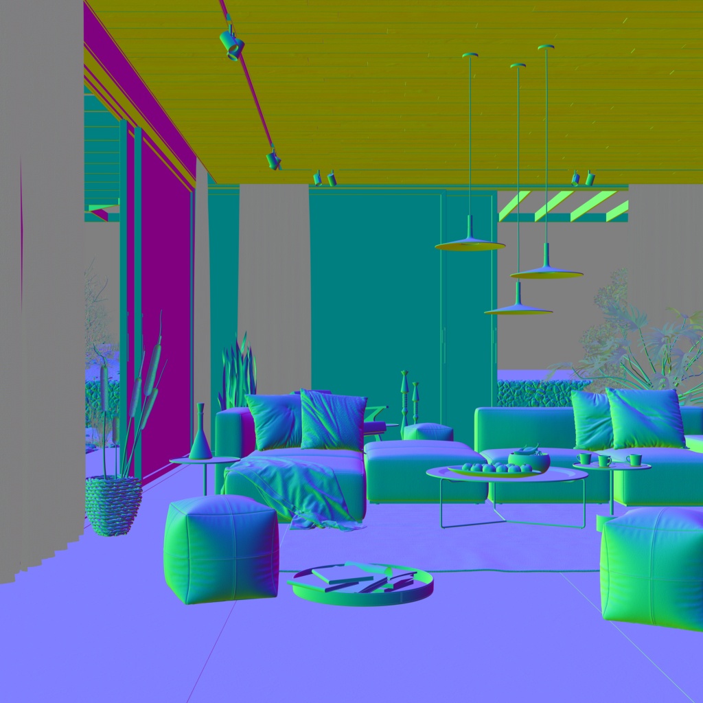
Sampler Info Render Element with Type set to Normal vector with bump mapping
The following examples have the coordinate system set to object space.
Point Type in object space
Reflection vector Type in object space
Refraction vector Type in object space
The following examples have the coordinates system set to camera space.
Point Type in camera space
Reflection vector in camera space
Refraction vector in camera space
The following examples have the coordinates system set to relative space.
Point Type in relative space
Reflection vector Type in relative space
Refraction vector Type in relative space
Example: Re-texturing in composite
Using the Sampler Info Render Element it is possible to apply a new texture to an already rendered still or sequence via setting its type to UVW coordinates. This then enables the creation of what effectively amounts to a new Diffuse Filter Render Element which can then be used in a composite, enabling a change of texture to be easily made. It is worth noting that any UV stretching on the model will carry through into the UVW pass created by Sampler Info as can be seen in the examples below.
The Sampler Info with type set to UVW coordinates
(uvw mode = normal)
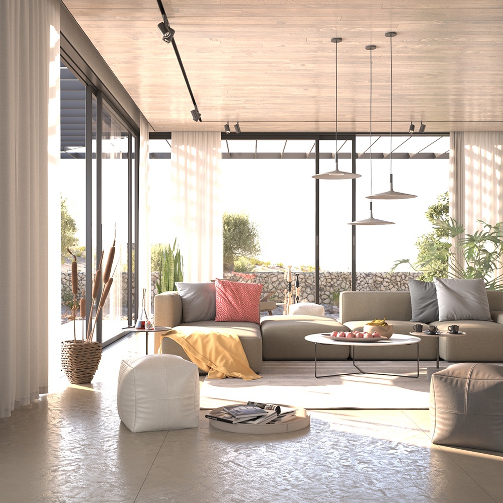
Beauty render prior to re-texturing in composite
New texture image applied in composite.
(This effectively creates a new Diffuse Filter Pass.)
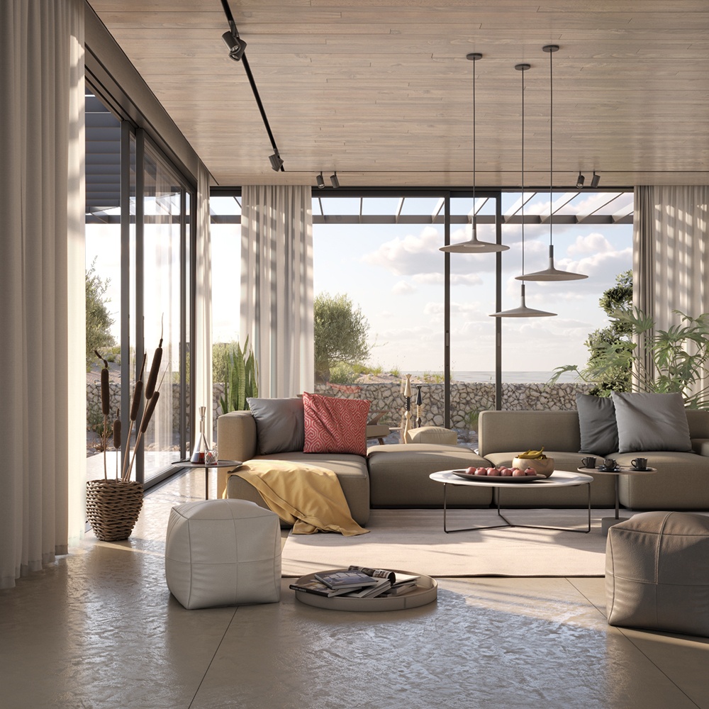
Re-textured Beauty render
(Done purely at a composite level)
V-Ray Render Options
The OptionRE render element affects the output of other render elements by giving access to a number of otherwise hidden options.
The OptionRE render element is a special render element that controls some internal settings for V-Ray that are otherwise inaccessible. This render element does not generate an image or data itself, but rather controls other render elements.
Parameters
The following options are accessible through the SettingsRenderChannels plugin.
unfiltered_fragment_method - Determines which fragment to use for unfiltered render elements. Possible values are:
- 0 - best coverage - For each pixel, the final values for the render element are taken from the object that has the largest contribution to that pixel.
- 1 - closest to camera - For each pixel, the final values for the render element are taken from the pixel that represents geometry closest to the camera.
deep_merge_mode - Determines how to blend fragments within a pixel. Controls the generation of deep data for deep OpenEXR 2 and VRST files. Possible values are:
- 0 - by render ID - Deep fragments within a pixel are merged based on the objects to which they belong (i.e. objects are differentiated based on their render ID as it appears in the render ID element).
- 1 - by Z-Depth - Deep fragments within a pixel are merged based on the similarity of their z-depth values. Use the deep merge deep_merge_coeff parameter to control how close fragments need to be in order to merge them.
- 2 - none
With the default setting of By render ID, V-Ray merges the deep fragments within a pixel that belong to the same object, in order to reduce the size of the deep data. This also allows for the perfect separation of the different objects if needed for post-processing purposes. However this might be undesirable, especially in cases with a single object that is a complex shape (i.e. one VRayProxy object that represents a large portion of the scene environment). In this case, setting this parameter to By Z-depth causes V-Ray to separate the deep fragments based on the similarity of their z-depth values, rather than to which object they belong.
- deep_merge_coeff - Determines the z-depth blending sensitivity when deep_merge_mode is 1.
- deep_exclude_RGB – (Boolean) Excludes the RGB color channel from deep files.
V-Ray Denoiser
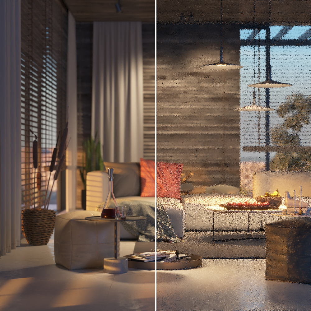
The Denoiser Render Element removes noise from other render elements and saves its results in a few different ways.
The Denoiser takes an existing render and applies a denoising operation to it after the image is completely rendered out via normal means. The denoising operation detects areas where noise is present and smooths them out.
Because the Denoiser operates on other render elements (such as Beauty | RGB_Color) rather than being part of the rendering process itself, the denoising operation does not require rerendering of the scene. The Denoiser settings can be quickly changed and tested over and over to improve the result.
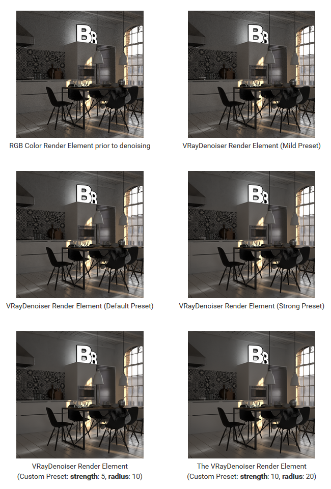
The Denoiser has three preset options for its settings: Default, Mild, and Strong. Parameters can also be adjusted directly by selecting the Custom preset.
When rendering, the Denoiser automatically adds a few render channels in the V-Ray frame buffer which are required by the denoising algorithm. Some of them are standard render channels like the diffuse filter color, the reflection filter color etc. A few special channels are also generated:
The noiseLevel channel is the amount of noise for a pixel as estimated by the V-Ray image sampler.
The defocusAmount channel is non-black when depth of field and motion blur are enabled and contains the estimated pixel blurring in screen space.
The Denoiser channel contains the result of the noise removal. If mode is set to Replace RGB element with denoised result, the denoised result replaces the RGB Color channel and is not present separately in the VFB.
Parameters
This render channel is obtained through the RenderChannelDenoiser plugin.
- name - String (The name of the render element containing the denoised image.)
- enabled - Whether the denoiser is enabled.
- enableDeepOutput - Specifies whether to include this render element in deep images.
- engine - Specifies the denoising engine to use.
- 0 - Default V-Ray denoiser - It is slower but may produce better results and has a version that runs on CPUs
- 1 - NVIDIA AI denoiser - It is very fast but may be less accurate and requires a compatible NVIDIA GPU.
- 2 - Intel Open Image Denoise - It is fast and runs on CPUs (it utilizes advanced instructions sets like AVX2, AVX512). Note that the three denoising engines use slightly different render elements.
type - (deprecated) Specifies whether to denoise only the RGB Color Render Element, or others as well. Possible values are:
- 0 - One-pass denoising on RGB channel only - Does a single pass at denoising on only the RGB Color Render Element, using other elements like the diffuse filter only to guide the denoising process. This method is better at cleaning up noise, but may loose small texture details or may blur too much areas of the image where multiple effects are visible at the same time (f.e. reflections and refractions through glass materials). This mode requires fewer additional render elements and you can use the Depending on denoising type setting of generate render elements to generate just the needed ones for this mode.
- 1 - Denoise render elements separately - Denoises the lighting, global illumination, specular, reflection, refraction and atmosphere render elements separately and combines them into one denoised version of the RGB image. This method preserves texture details better, but with low settings may fail to clean up some types of noise. Note: This mode can only work correctly if no color mapping is applied to the render, so that the mentioned render elements add up correctly to the RGB image.
preset - Offers presets to automatically set noiseLevelMultiplier and radius values. For more information, see the Denoising Presets example below. Possible values are:
- 0 - Only generate render elements
- 1 - Mild denoising - Applies a more subtle level of denoising than the Default preset.
- 2 - The default denoising mode - Applies a mid-level denoising.
- 3 - Strong mode - Applies a stronger level of denoising than the Default preset.
- 4 - Custom radius and noise thresholds - Allows the noiseLevelMultiplier and radius parameters to be set to custom values.
Note that preset does not apply to NVIDIA AI denoiser and Intel Open Image Denoiser.
- mode - The way the denoiser operates.
- 0 - Only generate the needed render elements without running the denoiser.
- 1 - Hide the channel with the denoised result in VFB.
- 2 - Show the channel with the denoised result in VFB.
- strength - The main denoiser control. Lower values modify the original image less, but may fail to clean up noise. Larger values are more effective at denoising, but may cause loss of detail. 0.5 is for mild denoising, 1.0 for normal strength and 2.0 for strong denoising.
Note that strength does not apply to NVIDIA AI denoiser and Intel Open Image Denoiser.
radius - Specifies the area around each pixel to be denoised. A smaller radius affects a smaller range of pixels while a larger radius affects a larger range, which increases the noise removal.
Note that radius does not apply to NVIDIA AI denoiser and Intel Open Image Denoiser.- noiseLevelMultiplier - Denoiser strength, a multiplier for the noise level render element from V-Ray.
- useGPU - Enable usage of GPU version if OpenCL support is found.
Note that useGPU does not apply to NVIDIA AI denoiser and Intel Open Image Denoiser. - silence_optix_init_error - V-Ray denoiser may be chosen over the NVIDIA denoiser in the event of initialization failure even if the latter is explicitly selected. This flag determines whether the full error message should be printed to the user or not.
- wrap_around_borders - Specifies that the denoised image can be wrapper around the left/right border. The denoiser can then use this information to avoid generating artifacts over the seamed area.
- temporal_mode - Specifies if NVIDIA AI denoiser should use temporal mode. Recommended for animations.
- denoise_alpha - Specifies if the alpha channel should be denoised.
- optix_use_upscale - When denoiser mode is NVIDIA, specifies if the denoiser should upscale.
Suggested Render Settings
While the denoiser can be quite effective at removing noise, it is not perfect; very noisy images can lead to artifacts and loss of image detail. For most scenes, use Bucket or Progressive image sampler with the Noise threshold set to 0.05 or lower. Additionally, the denoiser works best when the noise levels across the image are similar (the noiseLevel render channel is uniform grey), so using very low sampling is not recommended.
When rendering animations, enabling the Lock noise pattern option in the Global DMC rollout generally improves the results. Using the Standalone vdenoise Tool on the rendered frames can additionally improve the quality of the animation.
Example: Denoising Presets
The example below illustrates how Denoiser works using the presets. A purposely noisy render was set up using the Progressive Image Sampler Type with Render Time set to only 3 minutes to leave plenty of noise in the render. To better see the noise level in each image, click the image to see it at full size.
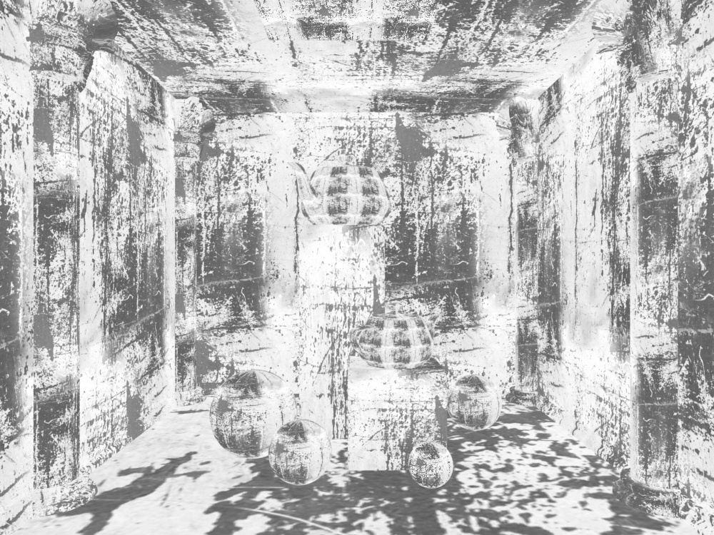
Example: noiseLevel Render Element
The noiseLevel Render Element shows where areas of noise have been detected in the scene. White areas have the most noise, black areas have no noise, and gray areas have varying levels of noise.
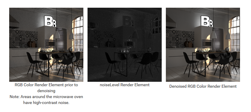
Image denoising takes place after the frame has been rendered and does not show up until all rendering has finished.
Textures or materials such as VRayStochasticFlakesMtl that could be considered to have a purposely noisy look are not considered "noisy" by the Denoiser, and are not affected by the noise removal process.