This page provides a tutorial on creating a Ship in the Ocean simulation with Chaos Phoenix in 3ds Max.
Overview
This is an Advanced Level tutorial. The workflow for setting up the shot, and the Phoenix settings involved in the simulation are explained in detail. However, it's recommended that you have at least basic knowleage in lighting, materials, and the Phoenix simulation.
This tutorial is created using Phoenix 4.41 Official Release and V-Ray 5, Update 2.2 Official Release for 3ds Max 2018. You can download official Phoenix and V-Ray from https://download.chaos.com. If you notice a major difference between the results shown here and the behavior of your setup, please reach us using the Support Form.
The instructions on this page guide you through the process of creating a simulation of a ship sailing through the ocean using Phoenix and 3ds Max.
The process of correctly setting up the scale of the objects used in the simulation is covered in detail. Many workflow suggestions and example videos of commonly used simulation parameters are included as well.
The main takeaway from this tutorial is an intuitive understanding of how the Foam and Splash parameters work together to produce foam from the collision of the vessel with the liquid surface.
We also take a look at an advanced setup allowing you to simulate multiple vessels in separate Phoenix Simulators and merge them into a single infinite ocean at render time.
To download project files: Download Project Files
Want to follow along but don’t have a license?: Download Free Trial

Units Setup
Scale is crucial for the behavior of any simulation. The real-world size of the Simulator in units is important for the simulation dynamics. Large-scale simulations appear to move more slowly, while mid-to-small scale simulations have lots of vigorous movement. When you create your Simulator, you must check the Grid rollout where the real-world extents of the Simulator are shown. If the size of the Simulator in the scene cannot be changed, you can cheat the solver into working as if the scale is larger or smaller by changing the Scene Scale option in the Grid rollout.
The Phoenix solver is not affected by how you choose to view the Display Unit Scale - it is just a matter of convenience.
As the focus of this tutorial is a large-scale ship simulation, setting the units to Meters seems like a reasonable choice.
Go to Customize → Units Setup and set Display Unit Scale to Metric → Meters.
Also, set the System Units such that 1 Unit equals 1 Meter.

Geometry Setup
If you open one of the provided scene files - Phoenix_ShipInTheOcean_3dsMax2018_Start.max, you will find an animated camera and the ship geometry.
In this example, the ship is already set up to be of proper, real-world size.
However, that may not be the case with your ship or boat so let's see how to go about fixing this.
- Try to find some information regarding the real world size of your model. The object in this scene is a replica of a typical Navy warship. Wikipedia tells us that the length of the ship is 154 meters. If your model is fictional or you can't find any info, use the measurements of an object that somewhat resembles yours.
- Create a Box around your object with the Width / Length / Height set up as a reference. In this example, the Length of the ship should be 155 meters, its Beam (Width) 20 meters, and it should 'sink' (Draft) 9.2 meters into the water.
- If your model doesn't fit into the specified measures, use the Scale tool to uniformly scale it down until it is of the correct size.
That is all. Please don't delete the measurement box for the time being - you are going to need it when setting the Phoenix Liquid Simulator Initial Fill Up level.

The ship in this example is already animated for you. The speed of your model will heavily affect the entire simulation. It is crucial that you are mindful of the speed of your ship as it travels through the liquid.
Here is how to approach the animation methodically.
- Either use the Internet to find how fast the real-world version of your model is/or if fictional, consider using something with similar properties as a starting point (i.e. if you're simulating a Medieval warship, find out how fast a typical Navy warship from that era was). The speed of this vessel is 56 km/hour, according to Wikipedia. That's 56 000 meters / 3600 seconds, or 15.56 meters per second.
- The Frame Rate in this example is set to NTSC 30 frames per second. Therefore, 15.56 meters / 1 second is 15.56 meters / 30 frames = ~0.5 meters per frame. As a side note - you can edit the Frame Rate from the Time Configuration window whose button is right next to the Set Keys button in the bottom right.
- Recall that the Units Setup is set to meters, therefore 1 unit is 1 meter. That means our ship should travel about 1 unit for every 2 frames.
- Determine the length of your simulation. In this example, the length is 1000 frames. Therefore, our ship should travel ~500 units over those 1000 frames at top speed.
- Create the animation. In this example, the keyframes are as follows: [Frame 0 Translate Y (0)]; [Frame 1000 Translate Y (400)].
- Open the Curve Editor and set the tangents for the animation to Linear. It would look strange if the ship was speeding up at the start and slowing down at the end of the animation, which is the default behavior of the Ease-In - Ease Out tangents setup by 3ds Max.
That is all. Play the animation to make sure everything is working correctly.

If you find that the speed of your vessel is too high and the waves generated at the front are too big, you can easily reduce the speed by setting the Translate Y values to a lower number. Please check the example videos below.
High speed: Animation from 0 to 500 in Y
Low Speed: Animation from 0 to 350 in Y
Simulation
Before we begin, here's an optimization tip that will save you a lot of R&D time when working with setups similar to the one described here.
The motion and behavior of the secondary particle effects (such as Foam, Splashes, Mist and Drag particles) can vary depending on the resolution (Cell Size) of the Phoenix Simulator. For this reason, it is possible that working at a low resolution until you're satisfied with their appearance and then increasing the number of cells may not produce a simulation that completely matches your expectation.
A good approach would be to instead work at a higher resolution while only simulating one side of the Phoenix Container. This will reduce in half the number of simulated cells and the time it takes for the simulation to complete. Furthermore, the motion of the secondary particles will match one-to-one when you decide it's time to restore the container back to its original size.
For clarity's sake, the rest of this tutorial will not make use of the suggestion above. However, this trick is a huge time saver so consider incorporating it into your workflow.

Consider the Simulator size required by a meteor flying through the air or a ship sailing through the ocean - the simulation time and memory requirements of a Simulator spanning the entire path of the object would be enormous.
Instead, Phoenix provides a feature called Motion Inertia that allows you to confine the simulation to a small portion of the path of a moving piece of geometry. This allows you to link the simulation box to the geometry and reduce the size of the grid to a more manageable resolution. The movement of the Simulator in your scene will then affect the liquid inside the grid. This is an immense performance boost that you should aim to take advantage of whenever possible.
Go to Frame 0 so the ship is centered at the origin.
Create a Phoenix Liquid Simulator and position it such that the front of the ship is close to the +Y wall of the Simulator. Be sure to leave some extra space at the back of the ship - that way, the foam generated by the ship as it travels through the water will spend enough time inside the Simulator to form interesting patterns.
Speaking of foam, Phoenix provides another feature to boost performance - Foam particles can live outside the bounds of the simulation box. What this means is that you can have a very long trail of Foam particles generated by a relatively small Simulator.
Here are the exact dimensions and position of the Phoenix Liquid Simulator at Frame 500 (so the ship is centered at the origin):
Translate: [X: 0] [Y: -40m] [Z: 4m];
Grid Size: [X: 205] [Y: 512] [Z: 20];
Cell Size: 0.5m;
Scene Scale: 1.0.
Optionally, you can rename the PhoenixFDLiquid001 to phx_simulator_01 to keep your scene organized.

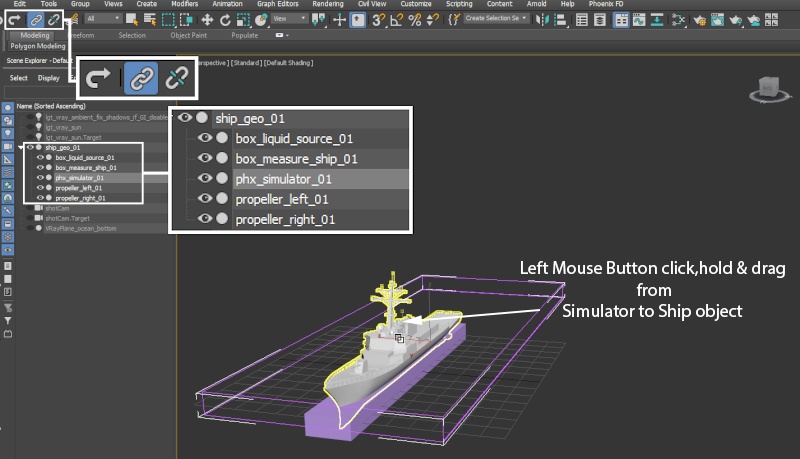
Go to Frame 0 and use the Select and Link button and the top left side of the 3ds Max UI to link the liquid Simulator to the ship geometry.
This is done by Left-Mouse-Button click, hold and drag from the Phoenix Liquid Simulator to the ship geometry.
To test if the link has been successful, scrub the Timeline. The Simulator box should now follow the animation of the ship.
Unhide the box used to measure the ship size. Recall that the Draft (the sink level) is 9.4 meters. The Draft is measured from the lowest point of the ship so if you were to position the box such that its bottom face is aligned with the bottom of the ship, its top face will give you the Draft.
Then, open the Dynamics tab and enable Initial Fill Up.
Hit the Start button in the Simulation rollout or the Phoenix side panel to simulate 1 frame so you can get a preview of the liquid particles.
Notice the water level. This is controlled by the Initial Fill Up parameter and it defaults to 50. 50 means 50% of the height/vertical size of the Phoenix Simulator. Set the Ocean level such that the liquid particles barely cover the measurement box. In this example, an Initial Fill Up level of 25% is sufficient.
You may now run the simulation for a couple of frames to make sure everything is working as expected.
Make sure to either hide the measurement box or add it to the Phoenix Simulator → Scene Interaction rollout → Exclude List so the liquid is not affected by it. This way the simulation will completely ignore it. Not doing so will cause the box to become an obstacle to the fluid and thus the particles inside it will be killed because it's Solid by default.

Under the Dynamics rollout, set the Steps Per Frame to 1.
The Steps Per Frame parameter is most useful when creating fast-moving / turbulent liquids. In the case of a ship moving through a calm liquid surface, the computational cost of higher SPF will have no benefit while slowing down the simulation. Higher Steps per Frame decrease the performance linearly - double the SPF means double the simulation time. For detailed information and examples, please check the Steps Per Frame documentation.

If you'd like to get a preview of the meshed liquid surface, head over to the Preview tab of the Simulator and enable Show Mesh.
You may also disable the preview of entire groups of particles (such as Liquid, Foam, Splashes, etc.) from the Particle Preview section of the Preview rollout.

Let the simulation run for 100 or so frames and take note of the lack of interesting movement in the liquid at the back of the ship.
In real life, the liquid at the back of the ship is pushed backward by the propellers. The easiest way to emulate this effect is to simply use a box as a source geometry for a Phoenix Liquid Source - thus adding additional liquid and velocity into the simulation. Depending on the type of vessel you are creating and its size, you should tweak the placement and scale of the source geometry. If you're making a jetboat simulation, you may also try to give it a slight rotation so it points upwards.
Naturally, we want the box to move with the ship so it's linked for you in the same manner as the Phoenix Simulator using the Select & Link button at the top left of the 3ds Max UI.

Without emitter at the back of the ship
With emitter at the back of the ship
Proceed by creating a Phoenix Liquid Source and specifying the box_liquid_source geometry as the emitter.
Set the Outgoing Velocity to 14m. This parameter can be edited depending on the type of simulation. For a jetboat, the Outgoing Velocity would be much higher than it is for a massive ship like the one in this example. Please check the comparison preview videos below.

Without Liquid Source at the back of the ship
With Liquid Source at the back of the ship
At the moment, the Liquid Source is pushing liquid in all directions. It may be hard to notice when the Outgoing Velocity is set to a low value so check the example videos below.
To resolve this, you can tell the Phoenix Liquid Source to only emit from the back face of the box_liquid_source.
Select the box_liquid_source, add an Edit Poly modifier, go to Face selection mode and set the ID for all faces to 1. Then, select only the face pointing in the -Y direction and set its ID to 2.
Specify the Polygon ID for emission to be 2 at the bottom of the Phoenix Liquid Source parameters panel.

In this tutorial, the Foam particles that generate the trail of the ship are created from Splash particles. Splash particles, on the other hand, are born when the liquid surface is turbulent. Not only will the simulation look better but you get foam and splashes for free. Check the FLIP Particles Life Cycle page for more info.
If you'd like to have greater control over the foam trail at the back of your vessel, the most straight-forward approach would be to use this exact same technique mixed in with a different Outgoing Velocity, Modifiers, Texture maps for the Outgoing Velocity, or even using the Noise parameter of the Phoenix Liquid Source.
Emitting Without Polygon ID specified and high discharge
Emitting With Polygon ID specified and high discharge
We are now ready to start setting up the Splash and Foam parameters for the Phoenix Simulator.
Open the Splash/Mist rollout and select the Enable checkbox. Choose Yes when asked if you'd like a Phoenix Particle Shader generated for the splash particles. This will automatically set up the link between the splash particle group, the Particle Shader, and the Simulator.
![]()
Here's how this works:
- Splash particles are generated from the liquid particles.
- High Splash Amount means that more splash particles will be generated by a single liquid particle → Low Splash Amount means fewer Splash particles.
- High Splash Amount means that the size of the Splash particles will be smaller → Low Splash Amount means larger Splash particles.
This is done with the intention of preserving the liquid volume. X amount of liquid produces Y amount of splash particles. Then, when the splash particles enter the water, they are converted back into liquid particles. So Y amount of splash particles is converted back into X amount of liquid. This process is controlled by the Affect Liquid parameter at the bottom of the Splash/Mist rollout. The default value of 1 is what Phoenix considers a physically correct behavior that preserves the liquid volume.
The Liquid → Splash → Liquid example above is correct only in case the Affect Liquid parameter is greater than 0. If set to 0, Liquid particles are NOT killed when generating Splash particles, and Splash particles are NOT converted into liquid when they enter the body of water and die.
Increase the Splash Amount parameter to 20. The Splash Amount controls both the size of the splash particles and their number.
In this example, the Threshold is set to its default value of 10. However, keep in mind that you may want to increase it if the vessel you're using is moving faster. The Threshold controls where splash particles are generated and it is based on the curvature (how disturbed the surface is) of the liquid surface. If this value is low enough, even relatively flat areas of the liquid surface will produce splashes.
Set the Splash to Mist parameter to 0. Mist particles are a great way to add additional detail into the simulation but since the camera is rather far from the ship and they won't contribute much to the final shot, it would be a waste of time and resources to simulate them.
Set the Splash Air Drag to 5. As the name implies, this will add additional drag to the splash particles, causing them to travel a shorter distance. You may want to edit this parameter depending on the type of vessel you're simulating. For instance, if simulating a jetboat, this value would be best left at its default of 1.
Increase the Max Outside Life parameter. Here, it's set to 4. If a Splash particle leaves the Simulator and its outside life is set to 0, it will be instantly deleted. Because the simulation box in this example is quite short (small in the Z axis), it's possible many of the splash particles generated at the front of the ship will rise high enough to leave the bounds of the liquid Simulator and be deleted.
Increase the Liquid-Like to 1. This parameter controls the behavior of splash particles in the air. If the value is set to 0, they will behave as individual points in empty space. Increasing this value will force the particles to try and stick to each other, thus forming tendrils when ballistic.

Splash Amount 10
Splash Amount 20
Splash Threshold 3
Splash Threshold 10
Open the Foam rollout and select the Enable checkbox. Choose Yes when asked if you'd like a Phoenix Particle Shader generated for the foam particles. This will automatically set up the link between the foam particle group, the Shader, and the Simulator.
Set the Foam Amount to 0. This will disable the algorithm responsible for directly generating foam from the liquid surface. In this example, we generate the Foam from the Splash particles using the Foam on Hit parameter in the Splash/Mist rollout.
Set the Half Life parameter to 1.5. This option sets the time required for the particles to reduce to half of their initial count, in seconds. Affects only the foam bubbles above the liquid surface.
Increase the Max Outside Age parameter to 3. As mentioned earlier, the foam can live outside the bounds of the Phoenix Simulator - setting this parameter to 3 (seconds) ensures that the foam lives long enough to accumulate in the ship's path.
Set the Size to 0.05m. The Size parameter controls the size of the foam bubbles. Even though a real-life foam bubble is obviously not 5cm wide, here we can afford to use larger and fewer foam particles (because this is a distant shot) in order to optimize the sim. Foam Size works in conjunction with the B2B Interaction (B2B stands for Bubble to Bubble). For instance, a large bubble size coupled with high B2B Interaction will cause the particles to start colliding and pushing each-other - this can be very useful for simulating beer or bathtub foam.
Set the Size Variation Small / Large to 0 and 5 respectively, and the Distribution to 300. Those 3 parameters work with the Foam Size - with these settings, the largest bubbles will be no bigger than Size * 5, and the distribution will be such that there will be 300 times more average-sized bubbles than large bubbles.
Reduce the B2B Interaction to 0. This can be an expensive effect that is really not necessary for this type of simulation.
Set the Rising / Falling Speed to 0.5m and 5m respectively. Those parameters control the vertical speed of the foam particles.
Set Surface Lock to 0.5. This allows you to control the behavior of the foam inside the liquid. If the Surface Lock is set to 1, the foam will be forced to float exactly at the liquid surface, regardless of any motion that may otherwise temporarily force it to sink into the water. Setting it to 0 disables this behavior and the values in-between act as a multiplier for the effect.
Set the Patterns Strength to 0.5 and the Patterns Radius to 1.5m. Those 2 parameters control the Phoenix algorithm responsible for generating foam patterns over the liquid surface.
Let the simulation run for a couple hundred frames.

Open the Splash/Mist rollout and set the Foam Amount to 2. This will cause Foam particles to be generated when the Splash particles collide with the liquid surface.
Also, set the Depth to 4. The Depth parameter controls how far below the surface the Foam particles are born.

The Foam Lifespan is your main control for the length of the foam trails to the side and in the back of the ship. If a shorter foam trail is required for your simulation, reduce the lifespan accordingly. Also note that the longer the trails are (the higher the lifespan), the more bubbles will accumulate during the course of the simulation - this has the potential of slowing things down and consuming more memory.
The Foam Patterns section controls the distribution of the foam particles over the liquid surface. The Pattern Radius option controls the size of individual 'circles' while the Pattern Strength controls how strongly the forces which form the patterns are enforced.
Pattern Radius 1.5 + Pattern Strength 0.5 + Half-Life 1.5
Pattern Radius 6 + Pattern Strength 1.0 + Half-Life 10
Note how the particles are repelled unnaturally during the formation of patterns. To resolve a problem like this, a weaker Pattern Strength or a lower Pattern Radius could be the remedy.
B2B 0 + Foam Size 0.05 + Pattern Radius 1.5
B2B 100 + Foam Size 0.3 + Pattern Radius 6
Under the Dynamics rollout, set the Droplet Surfing parameter to 0.6. The Droplet Surfing option controls how long a particle separated from the main body of water will hover on the surface before it merges with the liquid. Increasing this parameter allows the Splash particles to slide along boat wake thus producing a wider trail of foam in the front of the ship.
Droplet Surfing is your main control for the width of the foam trail. Increasing it allows the liquid and splash particles to spread out by sliding over the liquid surface, instead of immediately stopping when they hit the liquid mass. Since Foam is born by the Splash particles, this would allow the foam trail to become wider. Reducing Splash Threshold would further enhance the effect.

The simulation parameters should all be set up now.
Increase the resolution of the grid to ~100 000 000 voxels by reducing the Grid → Cell Size parameter to 0.14.
Let the entire simulation cache to disk. This may take a while depending on the speed of your machine.
The Preview → Read Cache for Preview drop-down allows you to disable the loading of simulated cache files for Viewport preview. Depending on your machine and the resolution of your sim, this option could provide a decent speed boost. Consider setting the Read Cache for Preview option to Disable During Sim.

Simulation with Final settings at 5M Cells
Simulation with Final settings at 100M Cells
Rendering
Let's start by setting up the options in the Rendering rollout of the Phoenix Simulator.
Set the Mode to Ocean Mesh. If Preview → Show Mesh is enabled, this should generate a preview of the liquid ocean inside the camera's frustum. The Ocean Mesh mode generates a liquid surface from the boundaries of the Phoenix Simulator box.
The Ocean → Ocean Level parameter needs to be adjusted as well.
Recall that we used the Dynamics → Initial Fill Up parameter to set the initial liquid level for the Simulator. The Initial Fill Up is a simulation setting and cannot be altered without simulating again. The Ocean Level, on the other hand, is a rendering setting which you can freely edit at any point. It allows you to compensate for the liquid particles subsiding or going above the Initial Fill Up level during the simulation. The Ocean Level might not exactly match the Initial Fill Up level, even when set to the same value, and you will notice such mismatch right at the boundaries of the Phoenix Simulator where the generated infinite ocean connects with the Simulator's liquid surface. Because there are many situations where an automated solution might fail (such as the infinite ocean surface oscillating up and down until it settles which will cause the horizon to bounce), it is left to you to match the Ocean Level to its best value.
The easiest way to do this is to enable the Mesh Preview (Preview rollout) and start with the same value as the one set for Initial Fill Up in the Dynamics tab. Then, looking at the mesh preview, increase or decrease the Ocean Level in small increments until the generated ocean is leveled with the surface generated by the Simulator.
Set the Ocean Level parameter to the same value as the Initial Fill Up parameter.
If the border between the Simulator and the generated mesh is still visible, increase/decrease the Ocean Level in small increments until the generated surface is smooth.
In this example, the Ocean Level is set to 25.

Enable Displacement and click the No Map button next to the Map parameter.
Select a PhoenixFDOceanTex and set its Control by Wind Speed parameter to 5. The Wind Speed parameter will affect the height of the waves. A higher wind speed creates bigger waves and vice versa.
The Wave Height is set to 1, with Sharpness of 1, Velocity Coherence of 0 and Wave Crest of 0. You can find more information on those options in the Phoenix Ocean Texture documentation.
From the Coordinates tab of the PhoenixFDOceanTex, you may change the Angle Z to a value of your choice. This parameter is used to rotate the direction of the waves generated by the Phoenix Ocean Texture. It is a purely artistic decision so feel free to tweak the Z Angle as you see fit.

If you happen to notice a discrepancy in the detail between the water in the Phoenix Simulator and the rendered infinite ocean, increase the Ocean Subdivs parameter in the Rendering rollout. This will generate additional vertices for the infinite ocean mesh for each pixel of the rendered image which makes it possible for the Phoenix Ocean texture detail to come through. Keep in mind that increasing the Ocean Subdivs will cause rendering to consume more RAM so only do this in small increments. 1-3 Subdivs should suffice for most setups when rendering at Full HD 1920x1080. When rendering at a lower resolution, a higher Ocean Subdivs value may be necessary.
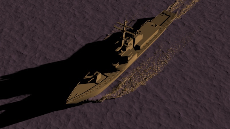
Here's how a rendered image looks so far. As you can see, there are several things in regards to the shading that need to be taken care of.
- The Particle Shaders for the Foam and Splash particles have less than ideal settings for this particular scene. We will first work on that.
- The liquid surface is using a default material and looks nothing like water. We will use a V-Ray Material to recreate the appearance of an ocean.
- The shadows cast from the V-Ray Sun are very dark. To resolve this, you can either enable Global Illumination or use an Ambient Light.

Water Material
Create a V-Ray Material and assign it to the Phoenix Simulator.
Set the Diffuse color to RGB: [0, 0, 0].
Reflect and Refract colors should be set to RGB: [255, 255, 255] - this will produce a completely transparent material if the Index of Refraction was set to 1 (which is the IOR of clear air).
Set the Refraction IOR to 1.33 - this is the physically accurate index of refraction of water.
If you were to hit render now, you'd notice that the water is completely transparent and certainly does not look like an ocean.
To resolve this, set the Fog color to RGB: [180, 220, 220] and reduce the Depth to 200. This should produce the type of shading you'd expect in a large body of water containing all sorts of particulates that interfere with the light rays.

Ocean Bottom
The provided scene file contains a V-Ray Infinite Plane already prepared for you. You can simply unhide it and you'll be good to go.
However, if you're working with a different file, you should create a V-Ray Plane and assign a simple diffuse V-Ray Material to it. Place it below the level of the water. In this example, it's translated to -50m in Z.
Here's why this is needed: the Fog Color parameter of the V-Ray material won't affect the Phoenix Particle Shaders (with a Liquid Simulator connected) unless the 'volume' of the liquid is capped. This is a V-Ray peculiarity that occurs because the Ocean Mesh / Cap Mesh rendering modes produce a one-sided sheet of geometry which isn't closed off like the regular Mesh mode.
So, if the mesh is not 'closed off' by some other geometry in the scene (such as a V-Ray Plane), the underwater particles will not be shaded with the Fog Color of the V-Ray Material.
Furthermore, flickering in the particles may occur when rendering out a sequence.

Phoenix Particle Shader
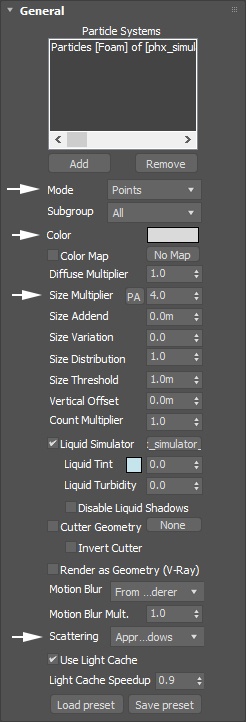
Select the Phoenix Foam Particle Shader and set the Mode to Points. The default option of Bubbles is better suited for close up shots. As the camera is far away from the ship, generating and rendering the bubbles is a waste of resources.
The Color is set to RGB: [181, 181, 181]. This is done so the foam doesn't appear too bright which will kill the detail - you are free to edit this value based on the requirements of your shot.
The Size Multiplier is set to 4. The Size options in the Particle Shader allow you to edit the Foam particle size after a simulation is complete. There is nothing stopping you from keeping this value at 1 and increasing the Foam Size in the Foam rollout of the Liquid Simulator instead, but that would require a re-run of the entire simulation.
If turned on, uncheck Disable Liquid Shadows. This option controls the lighting of the underwater foam particles. When Liquid Shadows are disabled, the foam particles inside the liquid are not tinted by its material's Fog Color. We'd like to get this tinting effect for additional realism.
The Scattering parameter should be set to Approximate+Shadows. The Approximate+Shadows options allows the for the foam to drop shadows over solid geometry in the scene.
The Motion Bur is set to From Renderer. The current renderer's own Motion Blur setting will be used.
You may want to decrease the Light Cache Speedup in case you notice flickering in the rendered animation. In this example, the value is set to 0.9. The Light Cache Speedup can significantly reduce the render times.
Open the Point rollout of the Foam Particle Shader and set the Point Alpha parameter to 0.017.
Set the Point Radius to 0.5. (If using Phoenix 4 or later, please set this value to 0.35).
This change will give a smoother appearance to the foam particles - the lower Alpha value will allow them to blend together and also reveal some of the liquid underneath.
The Motion Blur Step is set to 1. Motion blur in Point mode is calculated by cloning the particle several times and placing those copies along the particle trajectory. This parameter controls the distance between the copies. The smaller the step, the higher the quality, though at the cost of render time. Еxperiment with this option to find the best result for your scene.

Repeat the same changes for the Phoenix Splash Shader.
Because there is a large number of splash particles born at the ship's front, having no Motion Blur may cause the rendered animation to look unnatural.
Consider enabling Motion Blur for the Splash Particles Shader by settings the Rendering → Motion Blur option to Force On. Keep in mind that this will slow V-Ray down a bit.

 Point Alpha: 0.11
The foam appears noisy and rough
 Point Alpha: 0.017
The foam is smoother and blends nicely with the surface underneath
Lighting & V-Ray Render Settings
The provided scene file contains a V-Ray Sun & Sky setup.
You can find the V-Ray Sky texture in the Material Library.
The Intensity multiplier is set to 0.06.
The Sky Model is set to Preetham et al.
The Ground Albedo is set to RGB: [51, 51, 51].
Blend angle set to 5.739.
Turbidity is set to 3.0.
Invisible is enabled so the Sun does not produce noisy specular highlights over the ocean's surface.
The Shadow bias is set to 0.04m.
The Photon emit radius is set to 10.0m.
The sun is positioned relatively low on the horizon to produce yellow-ish illumination that is balanced by the blue lighting provided by the V-Ray Sky texture.

Set the V-Ray Sampler type to Bucket.
Set the Min subdivs to 1 and the Max subdivs to 12.
Set the Noise threshold to 0.01.
Set the Bucked width to 16.

Navigate to the GI tab and enable the Global Illumination.
Set the Light cache Subdivs to 1000.


Without GI
With GI
Multiple Ships Setup
Phoenix has an internal algorithm capable of merging multiple containers into a single infinite ocean. There is no special setup required.
Let's see how we can utilize the cache files of the ship simulation to add another ship into the shot.
- Right Mouse Button click over the Phoenix Liquid Simulator and select Clone. When prompted with the Clone Options dialog, select Copy and hit OK - the copy should now appear below the ship geometry and should be named PhoenixFDLiquid002 (if you kept the original naming).
- Repeat the same step for the ship geometry - the copy should be automatically renamed to ship_geo_002.
- Hide the original ship and the original liquid Simulator (named ship_geo_001 and PhoenixFDLiquid001).
- Use the Select and Link tool at the top left of the 3ds Max UI to link the new Simulator to the new ship - you will know the operation was successful if the copy of the Simulator (PhoenixFDLiquid002) now appears under ship_geo_002 in the Scene Explorer.
- Use the Transform tool to offset the ship (and make sure that you are transforming the ship and not the Phoenix Simulator) - the Simulator should follow it due to the link between them.
- Unhide the original ship (ship_geo_001) and the original Simulator (PhoenixFDLiquid001).
- Feel free to also copy any additional geometry that was linked to ship_geo_001, such as the propellers.

If you hit Render, Phoenix will prompt you with a message stating that the Rendering and Material options of the first Simulator (PhoenixFDLiquid001) will be used when merging your containers. This is referring to the options set in the Rendering tab and the Material assignment.
You will also notice that the Foam and Splash particles for the second Simulator are not rendered. We take care of that in the next step.

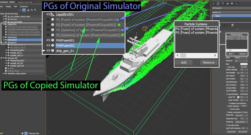
When you copied the Phoenix Liquid Simulator, a couple of new Foam and Splash particle groups were created as well. This is how Phoenix handles secondary effects - the Liquid particles are used to generate the surface while secondary effects like Foam, Mist, Splash, and Drag are separated in their own particle group(PG) nodes.
That way, you can use a single Particle Shader to render multiple particle groups with the same settings.
All you need to do is select a Particle Shader and use the Add button at the top to include a particle group to the Particle Systems list.
So, select PHXFoam001 and check the particle systems list. If the included particle system is called PG [Splashes] of system [PhoenixFDLiquid001], this means that this Particle Shader is used to set the rendering properties for the Splash particles of the Simulator called PhoenixFDLiquid001.
Add the corresponding particle group of PhoenixFDLiquid002 which, by default, should be named PG [Splashes] of system [PhoenixFDLiquid002].
Repeat the same process for PHXFoam002.
Hit Render.
You should now have 2 ships in a single ocean, with all the secondary effects rendered as well. The Phoenix Simulators should be seamlessly merged together.
Artifacts in the shading may pop up if the 2 Simulators overlap each-other. If possible, make sure that the bounds of the Phoenix Simulators do NOT overlap.
As a side note - there is nothing stopping you from using entirely different simulations instead of copying the Simulator and pointing it to the existing cache files. For instance, you could create a small jet boat simulation, make 5 copies of it and place those copies around the ship. You could try making an entire Naval Convoy this way.
