This page provides details on how to use the optimized Bump Material in V-Ray.
Overview
The V-Ray Bump Material gives the ability to add bump map and normal map effects when using any material.
Connect a material into the V-Ray Bump to add additional bump or normal map functionality. Stacking multiple Bump materials together can create a more complex surface material by allowing the use of several bump and/or normal maps together easily.
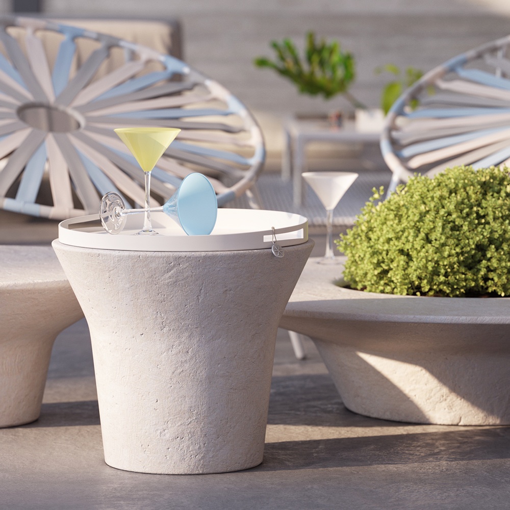
In the example, bump maps are used for the surface of the table. Both V-Ray Material and Bump Material can control the strength of the bump map by using a multiplier.

UI Paths
||V-Ray|| > Bump Material

||Create|| > V-Ray > Bump Material (disabled Separate menu for V-Ray materials)

Parameters
Base Material – Allows the user to select the base material to which the bump/normal effect is added.
Map Type – Allows the user to specify whether a bump map or a normal map effect is added to the base material.
Bump Map
Normal Map in Tangent Space
Normal Map in Object Space
Normal Map in Screen space
Normal Map in World Space
From Texture Bump Output –
Explicit Normal – Sets the normals to adhere to a specific value, rather than being dependent on a face. As a result, any changes made to the position of a face do not affect the normals, which remain unchanged.
For more information on each Map Type, see the Bump and Normal Mapping in V-Ray.
Texture Map – Specifies the bump/normal map that is used.
Bump Multiplier – A multiplier for the bump/normal effect.
Bump Delta Scale – Scale for sampling the bitmap when using bump mapping. The exact value is calculated automatically by V-Ray, but can be scaled here.
Bump Shadows – When enabled, V-Ray considers the bump maps when rendering shadows produced by objects with the bump material applied to them.

Enable Outlines – When enabled, adds outlines to the object the material is applied to. This option is disabled by default. Line Color – Determines the color of the outlines. A Texture can be applied. Line Width – Determines the width of the outlines in pixels. The soft limit is 100. Click on the Opacity – Determines how opaque the lines are. Click on the Outer Overlap Threshold – Determines when outlines are created for overlapping parts of the object. Lower values reduce the outer overlapping lines, while higher values produce more overlapping outer lines. Normal Threshold – Determines at what point lines are created for parts of the object with varying surface normals (for example, at the inside edges of a box). Lower values mean that only sharper normals generate an edge, while a value of 0.5 means that 90 degrees or larger angles generate internal lines. Higher values mean that smoother normals can also generate an edge. Don't set this value to pure 1.0, as this fills curved objects completely. Overlap Threshold – Determines when outlines are created for overlapping parts of the object. Lower values reduce the internal overlapping lines, while higher values produce more overlapping lines. Don't set this value to pure 1.0, as this fills the objects completely. Inner Line Control – When enabled, allows the inner line to be edited further. This option is disabled by default. Inner Line Color – Determines the color of the inner lines. A Texture can be attached Inner Line Width – Determines the width of the inner lines in pixels. Click on the Outlines
![]() arrow to expand. A Texture can be applied.
arrow to expand. A Texture can be applied.![]() arrow to expand. You can attach a Texture for the opacity. The Mix Strength option determines the percentage of blending between the Opacity value and the texture.
arrow to expand. You can attach a Texture for the opacity. The Mix Strength option determines the percentage of blending between the Opacity value and the texture.
Inner Line Control
![]() arrow to expand for the Texture option, where you can attach a texture to serve as the inner line width.
arrow to expand for the Texture option, where you can attach a texture to serve as the inner line width.
Options
MATERIAL ID
Material Id Enabled – Enables the use of Material ID.
Material ID – The color used by the Material ID render element. You can also use a shader here.
Multimatte ID – The integer ID of the material to be used by the Multi Matte render element.
ROUND EDGES
Round Edges Enabled – Enables the round edges effect which uses bump mapping to smooth out the edges of the geometry during render time.
Radius – Specify a radius (in world units) for the round edges effect. Since the actual geometry is not being changed and only the normals of the faces are affected, large values may produce undesirable effects.
Consider Same Object Only – When enabled, the rounded corners are produced only along edges that belong to the object which has the attribute applied. When disabled, rounded corners are also produced along edges formed when the object with the attribute intersects other objects in the scene.
Corners – Choose which edges are considered in the calculation. Possible options are:
Covex and Concave – Considers all edges.
Convex Only – Only applies Round Edges effect to edges with convex angles.
Concave Only – Only applies Round Edges effect to edges with concave angles.

Preview Settings
Override Preferences – When enabled, the parameters in this tab override the global preferences of the scene for the selected material.
Enable Preview – When disabled, the previews of the material in the Viewport and the Material Editor are disabled. The material is displayed in all black. This saves on processing power.
Enable Global Illumination – When disabled, global illumination is not calculated for the current material preview.
Quality – Determines the quality of the material previews. Higher values give more detail but slow down processing.
Editor Map Size – Determines the resolution of the material preview. If you have extra-detailed textures applied to the material, this option allows you to preview those textures in higher resolution at the preview step, without needing to render.
Default
64×64 (16 KB)
128x128 (64 KB)
256x256 (256 KB)
512x512 (1 MB)
1024x1024 (4 MB)
2048x2048 (16 MB)
4096x4096 (64 MB)
