This page provides information about the V-Ray Chaos Scans material.
Overview
The V-Ray Chaos Scans material (formerly known as V-Ray VRscans) allows the rendering of scanned BRDF material data stored in .vrscan files. These files are produced by Chaos's own internal material scanner and accompanying material creator software.
In V-Ray 6 and later, the Scanned Material doesn't require an additional render license.
In V-Ray versions prior to V-Ray 6, rendering Scanned Materials requires a separate license, otherwise images render with a watermark.
Starting with V-Ray 7, Update 1, Chaos Scans materials are available in Chaos Cosmos. They are marked with the Chaos Scans (![]() ) icon to distinguish them from other materials. Imported Chaos Scans materials require a separate Chaos Scans plugin license to be modified. However, they do not require a separate license to be downloaded or rendered.
) icon to distinguish them from other materials. Imported Chaos Scans materials require a separate Chaos Scans plugin license to be modified. However, they do not require a separate license to be downloaded or rendered.
The scanned material renders the captured appearance of an actual physical material sample, that has been scanned with special scanner hardware. The material goes beyond single-point BRDF capture and can faithfully represent the textured appearance of a large number of real-world surfaces using bidirectional texture function (BTF) approximation.
Because the scanned material simply reproduces the way a physical material responds to light, it has no notion of "diffuse" or "reflection" components, "normal" or "bump" maps.
The .vrscan files tend to be quite large as they need to pack a lot of data (they need to describe the BRDF of the material over its entire surface).
For more details on Chaos Scans, please see the Chaos Scans documentation or visit the chaos.com/scans website.

Common Parameters
File – The file name with the data for the scanned material; usually has a .vrscan extension.
Show UV Borders – Displays the borders of the material tile in the viewport on the object(s) that has the material applied to it. This only works with the DirectX viewports.
Tiling Factor – Global multiplier for U and V coordinates. See the Tiling Factor example below.
Two Sided – Forces the back-facing polygons to be shaded in the same way as the front-facing ones. If disabled, the back-facing polygons appear black. This can be useful for objects like curtains. Note that this option is always considered enabled when rendering transparent materials.
No Transparency – Turns off transparent properties of the material.
Use Triplanar Mapping – Ignores the object's default UV mapping and assigns one with U and V axes parallel to the nearest object-space axes.
Random Offset – (active when Use Triplanar Mapping is enabled) Randomizes the UV space offset. When rendering many instances using the same material, with this option enabled, you get variation of the look.
Random Rotation – (active when Use Triplanar Mapping is enabled) Randomizes the material rotation from one object to another. When rendering many instances using the same material, with this option enabled, you get variation of the look.
The Use Triplanar Mapping option is to be used with the Tiling Factor and does not work with the Repeat UV option of ImageFile or UV Channel nodes.

Appearance
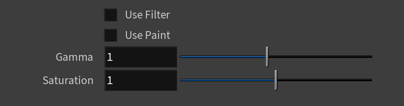
Use Filter – Enables the use of the color filter.
Filter Strength – Multiplies the effect of the filter.
Filter Color – A color multiplier for the material sample and can be used to tint the material (it affects the color of the reflections as well as a post effect).
Use Paint – Enables the use of Paint Color.
Paint Strength – Multiplies the effect of the paint.
Paint Color – Changes the color of the material without loosing the texture or changing the reflection color. For example, changing the color of wood or leather without losing their textures.
Gamma – Adjusts the gamma of the material (including Filter Color and Paint Color if used) as a post effect.
Saturation – Controls the saturation of the material (including Filter Color and Paint Color if used) as a post effect. See the Saturation example below.
Advanced Parameters
Trace Depth – Specifies the number of times a ray can be reflected. Scenes with lots of reflective and refractive surfaces may require higher values to look correct. A value of -1 specifies this option is controlled by the global Render Settings.
Cutoff – Specifies a threshold used to speed up reflections. If the contribution of reflections falls below this threshold, the reflections are not traced. This is similar to the Cutoff threshold of the V-Ray Material.
Bump/Parallax Zone – Determines the point where additional bump and parallax no longer exist and only natural height effects remain. This option is especially useful in side views of the material, where it might appear flat or less detailed. A value of 0 adds no additional bump and parallax. Value of 1 adds additional bump and parallax equally regardless of the view angle. All scanned materials by default have the most suitable value loaded for this parameter to achieve the most realistic look. For full control over the bump and the parallax, set the value to 1 and work with the Parallax and Bump Multipliers.
Parallax Mult – Adjusts additional parallax and edge displacement strength.
Bump Mult – The coat layer has a built-in bump map stored in the material sample file. This controls the strength of that bump.
Sampling Type – Determines which samples are taken around pixels involved in "blurry" effects such as anti-aliasing, depth of field, indirect illumination, area lights, glossy reflections/refractions, translucency, motion blur, etc.
Importance sampling – Bases the number of samples allocated to a value on the importance when it comes to things like distance from the camera or if more samples are needed to render a realistic result.
Uniform sampling – The number of samples is evenly taken over the entire image.
Plain Materials – Provides several interpretation modes for the textures inside the material (if present).
None – Used to view the material as it is with all the maps.
Average BRDF – Averages the BRDF and can be used to speed up the rendering for previews. Because texture details are removed, this also removes any tiling artifacts that might arise if the scanned sample does not tile very well. UV coordinates are still needed because most BRDFs are slightly anisotropic.
Average Isotropic BRDF – Smooth representation of the material with no maps visible.
Displacement – Enables displacement if supported by the material.
No Cached Light – Disables the cached light for the material, ensuring physical accuracy without the need to switch off GI of the entire scene. Disabling this option results in faster, but less physically accurate render.
Fast Volumetric Translucency – (relevant only to V-Ray scanned materials that are volumetric translucent) When enabled, the calculation of the volumetric translucency is fast, but less accurate.
Prevent Color Bleeding – When enabled, prevents the objects/surfaces from being colored by reflection of colored light from nearby surfaces.

Clear Coat
Clear Coat Enable – Enables the tracing of a clear coat layer for the material.
Clear Coat Highlights – Enables highlights from point light sources for the coat layer.
Clear Coat Strength – Specifies the strength of the coat reflections.
Clear Coat IOR – Determines the IOR of the coat layer, and from that controls the strength of the reflections. A value of 1.0 does not produce any reflections and disables the coat layer. Higher values produce stronger clear coat reflections. The .vrscan files typically contain the correct value for this parameter and it is set automatically when the file is loaded.
Clear Coat Bump – The coat layer has a built-in bump map stored into the material sample file. This parameter allows control over the strength of that bump.
Clear Coat – Specifies a clear coat multiplier.
Clear Coat Multiplier – Multiplier for the clear coat.
Clear Coat Coloring – Colors the coat reflections.
![]()
Developer
I know what I am doing – When enabled, opens the options enumerated below.
Scene Scale – Specifies a percentage for the original scene units of the scene.
Subdivs – Controls how many reflection rays are traced for the material. Note that the material does not have a "diffuse" or "reflection" component; everything is considered glossy reflection.
Depth Mult – Specifies a strength multiplier for the depth.
Direct Light Multiplier – Specifies a strength multiplier for the material's direct lighting.
Reflected Light Multiplier – Specifies a strength multiplier for the material reflection.
GI Lighting Multiplier – Specifies a strength multiplier for the material's global illumination.
Transparency Multiplier – Specifies a strength multiplier for the material transparency.
Retrace – Improves the precision of Global Illumination in cases where the light cache produces too large an error. This is especially obvious near corners where light leaks might be possible because of the light cache interpolation.
Don't use GI for Primary Rays – An approximation of Global Illumination for improving rendering speed. Controls whether to use GI for primary (camera) rays.
Dome – Enables or disables dome lighting.
Disable Enlargement – Disables the material from being enlarged.

Example: Tiling Factor
This example shows the effect of the Tiling Factor parameter. The .vrscan material used for the example is Leather.
Tiling Factor = 0.5

Tiling Factor = 0.75

Tiling Factor = 1

Tiling Factor = 1.5
Tiling Factor = 2
Move the slider to see the example renders.
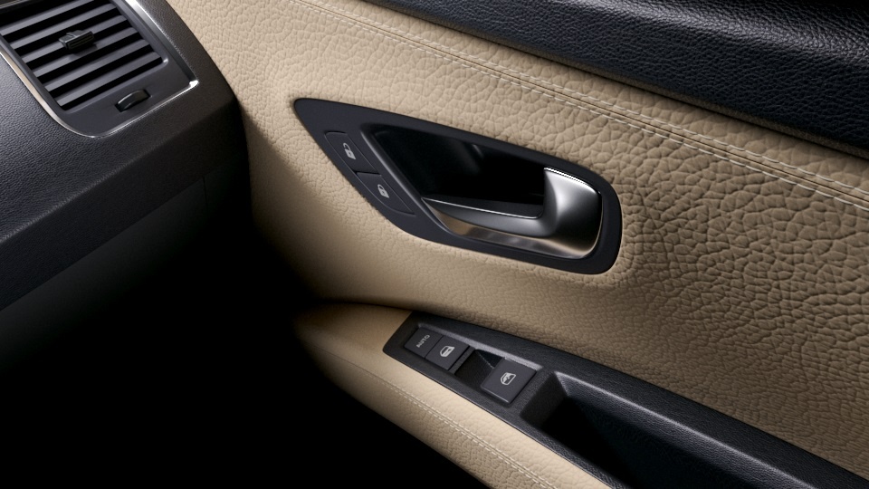
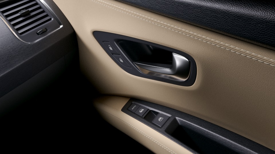
Example: Saturation
This example shows the effect of the Saturation parameter. The .vrscan material used for the example is Leather.

Saturation = 0.5
Saturation = 1
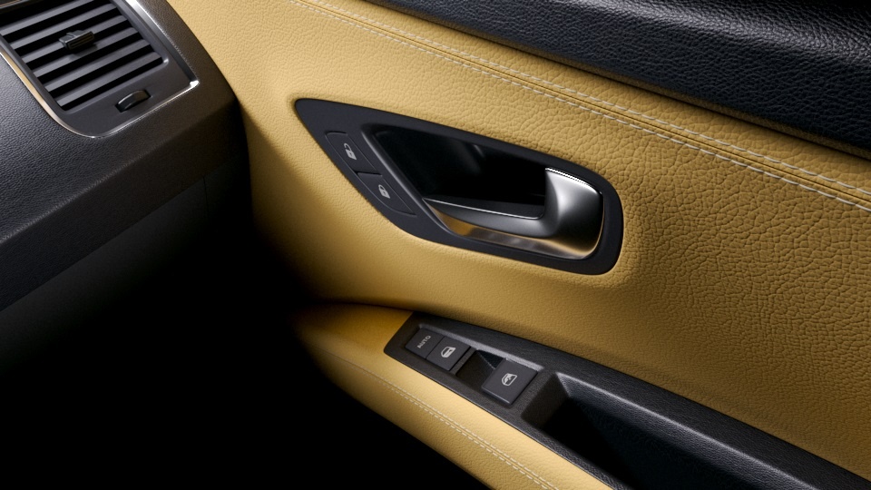
Saturation = 2
Move the slider to see the example renders.