This page provides information about the V-Ray Material node in V-Ray for Cinema 4D.
Overview
Furthermore, with the V-Ray Material, you can apply different texture maps, control the reflections and refractions, add bump and displacement maps, force direct GI calculations, and choose the BRDF for how light interacts with the surface material.
For examples of the different parameters, see the Classic V-Ray Material page.
If you wish to disable the material preview or adjust its quality to save processing power, you can do so from the Material Node.

Diffuse
SHADING MODEL
Mode – Gives the ability to switch between the Open PBR shading model and the V-Ray model. The Open PBR model differs in its structure from the V-Ray model. See more about the V-Ray Material Layers in the Render Theory article.
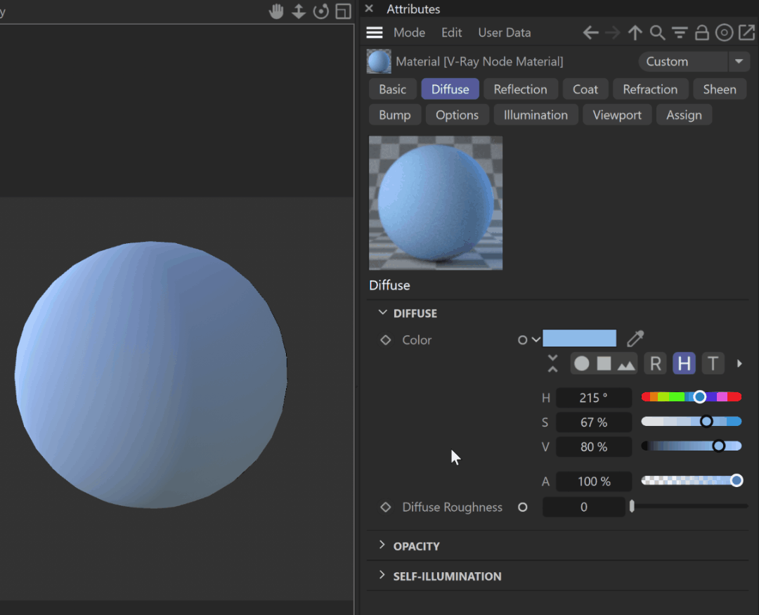
DIFFUSE
Color – The diffuse color of the material. Note: the actual diffuse color of the surface also depends on the reflection and refraction colors.
Diffuse Roughness – Used to simulate rough surfaces or surfaces covered with dust (for example, skin, or the surface of the Moon).
OPACITY
Color — Controls the transparency of the material, where white is opaque and black is fully transparent.
SELF-ILLUMINATION
Color – The self-illumination color of the material.
Self-Illumination Affects GI – When enabled, the self-illumination affects global illumination rays and allows the surface to cast light on nearby objects. Note, however, that it may be more efficient to use Rectangle Lights or the Light node for this effect.
Compensate Camera Exposure – When enabled, the intensity of Self-Illumination is adjusted to compensate the exposure correction from the Physical Camera.

Reflection
BRDF Type – Determines the type of BRDF (the shape of the highlight).
GGX – GGX Microfacet highlights/reflections. Specular highlights have a bright center with a longer falloff.
Phong – Phong highlights/reflections. Specular highlights have a bright center with no falloff.
Blinn – Blinn highlights/reflections. Specular highlights have a bright center with a tight falloff.
Ward – Ward highlights/reflections. SpecularF highlights have a bright center with a falloff broader than Blinn but tighter than Microfacet GTR (GGX).
Color – Specifies the reflection color of the material. Note that the reflection color dims the diffuse surface color.
Glossiness – Controls the sharpness of reflections. A value of 1.0 means perfect mirror-like reflection; lower values produce blurry or glossy reflections.
GGX Tail Falloff – Controls the transition from highlighted areas to non-highlighted areas when the BRDF Type is set to GGX.
Metalness – Controls the reflection model of the material from dielectric (metalness 0.0) to metallic (metalness 1.0). Note that intermediate values between 0.0 and 1.0 do not correspond to any physical material. This parameter can be used with PBR setups coming from other applications. The reflection color should typically be set to white for real-world materials. The metalness amount and its glossiness can be previewed in the viewport; see the example.
GTR Energy Compensation – Compensates GTR lost energy, and an accurate Fresnel formula for conductors is used for metals. This option is enabled by default for all newly created materials and is hidden from the UI. It is also hidden for Cinema 4D S24 and older versions, where it is forcefully enabled. It is visible in all other older scenes.
Use Roughness – This option controls how Glossiness is interpreted. When Use Roughness is selected, the Glossiness inverse value is used. For example, if Glossiness is set to 1.0 and Use Roughness is selected, this results in diffuse shading. Conversely, if Glossiness is set to 0.0 and Use Roughness is selected, this results in sharp reflection highlights.
Fresnel
Fresnel Reflections — When enabled, makes the reflection strength dependent on the viewing angle of the surface. Some materials in nature (glass etc) reflect light in this manner. Note that the Fresnel effect depends on the Index of Refraction as well.
Lock Fresnel IOR – Allows the user to unlock the Fresnel IOR parameter for finer control over the reflections.
Fresnel IOR – The Index of Refraction to use when calculating Fresnel reflections. Normally, this is locked to the Refraction IOR parameter, but you can unlock it for finer control.
Anisotropy
Anisotropy (-1..1) – Determines the shape of the highlight. A value of 0.0 means isotropic highlights. Negative and positive values simulate "brushed" surfaces.
Anisotropy Rotation – Determines the orientation of the anisotropic effect in a float value between 0.0 and 1.0 (where 0.0 is 0 degrees and 1.0 is 360 degrees).
UV Vectors Derivation – Assigns a placement texture node and changes its UV coordinates to control the direction of stretching of the highlights.
Local Object Axis – Uses a local axis for the anisotropy effect.
UV Space – Allows the user to assign a UVW Generator for the anisotropy effect.
Anisotropy Axis – Specifies a local object axis for the anisotropy effect when UV Vectors Derivation is set to Local object axis.
Thin Film
Enable Thin Film – Enables the Thin Film parameter.
Thickness Min (nm) – Determines the minimum thickness of the thin film in nanometers. If no Thickness Blend is applied, only this value is used for the thickness of the thin film.
Thickness Max (nm) – Determines the maximum thickness of the thin film in nanometers. This option is only available when Thickness Blend is applied.
Thickness Blend – Allows a map to be attached that blends the thickness values. If no map is applied, only the Thickness Min (nm) value is used to determine thickness.
Thin Film IOR – Specifies the reflective index of the thin film. A texture can be attached to this slot.
Texture – Specifies a texture file to be used for the Thin Film IOR.
Mix Strength – Specifies the blend amount for the texture file.
Reflection Advanced
Trace Reflections – Select this checkbox to enable reflections for the material.
Max Depth – The number of times a ray can be reflected. Scenes with lots of reflective and refractive surfaces may require higher values to look correct.
Enable Dim Distance – Allows you to stop tracing reflection rays after a certain distance.
Dim Distance – Specifies a distance, after which the reflection rays are not traced.
Dim Fall-off – A fall off radius for the dim distance.
Reflect on Back Side – When disabled, V-Ray calculates reflections for the front side of objects only. Checking it makes V-Ray calculate the reflections for the back sides of objects too.
Soften – Softens the edge of the BRDF at light/shadow transitions.
Affect Channels – Specifies which channels are affected by the reflectivity of the material.
Color Only – The reflectivity affects only the RGB channel of the final render.
Color+alpha – Causes the material to transmit the alpha of the reflected objects, instead of displaying an opaque alpha.
All channels – All channels and render elements are affected by the reflectivity of the material.

Metalness and glossiness viewport preview
When the V-Ray Material Node is attached to a geometry in the scene, and you apply Metalness, the amount of Metalness and its Glossiness or Roughness are displayed in the viewport.
Coat
Coat Color – Determines the color of the coat layer.
Coat Amount – Specifies the blending weight of the coat layer. A value of 0 does not add a coat layer, while higher values blend the coat gradually.
Coat Darkening – The coat is darkened due to multiple reflections within it. This mimics the effect of coats such as varnish, which have this effect on their bases. The darkening effect increases as the Coat IOR increases, and there is no darkening if the base is white.
Coat Glossiness – Controls the sharpness of reflection. A value of 1.0 means perfect glass-like reflection; lower values produce blurry or glossy reflections. If Reflection Use Roughness is enabled, this parameter works as Coat Roughness.
Coat IOR – Specifies the Index of Refraction for the coat layer.
Bump
Coat Bump Lock – When enabled, it prioritizes the base bump map during rendering over the coat bump map. You can use it to temporarily hide the coat bump.
Coat Bump Map – Specifies the bump/normal map used as a coat bump.
Coat Bump Amount – A multiplier for the coat bump effect.
Coat Bump Type – Allows the user to specify whether a bump map or a normal map effect is added.
Bump Map
Normal Map in Tangent Space
Normal Map in Object Space
Normal Map in Screen Space
Normal Map in World Space
From Texture Bump Output
Explicit Normal

Refraction
Refraction Glossiness – Controls the sharpness of refractions. A value of 1.0 means perfect glass-like refraction; lower values produce blurry or glossy refractions.
Refraction IOR – Index of Refraction for the material, which describes the way light bends when crossing the material surface. A value of 1.0 means the light does not change direction.
Affect Shadows – This parameter causes the material to cast transparent shadows to create a simple caustic effect dependent on the refraction color and the fog color. For accurate caustic calculations, disable this parameter and instead enable Caustics. Simultaneous usage of both Caustics and Affects Shadows can be used for artistic purposes but does not produce a physically correct result.
Refract Thin Walled – When enabled, the Fog Scattering mode is set to SSS. It simulates thin translucent surfaces such as soap bubble, leaves, curtains, etc. The SSS Color defines the backside color, while the SSS Amount controls the translucency effect.
Translucency
Translucency Type – Selects the algorithm for calculating translucency (also called sub-surface scattering). Note that refraction must be enabled for this effect to be visible.
None – When selected, the only available parameters are the Fog Color and Fog Depth. Together with the Refraction Color, they determine the attenuation of light as it passes through the material. In this mode, there is no subsurface scattering.
Volumetric – Works together with the Refraction Color to scatter light inside the object. It is useful for liquids and other highly transparent materials. The Refraction Color and Refraction Glossiness determine, respectively, how much of the object's interior is visible and how rays interact with the object’s surface.
SSS – Works independently of the Refraction Color/Glossiness and is useful for skin, wax, marble and other relatively opaque materials.
None
Fog Color – The attenuation of light as it passes through the material. This option helps simulate the fact that thick objects look less transparent than thin objects. Note that the effect of the fog color depends on the absolute size of the objects and is therefore scene-dependent.
Depth (cm) – Controls the strength of the fog effect. Higher values reduce the effect of the fog, making the material more transparent. Smaller values increase the fog effect, making the material more opaque.
Volumetric
SSS Amount – Blends between full scattering and pure refraction.
Scatter Color – Controls the scattering. This parameter can be mapped with a texture.
Fog Color – Controls the absorption of the material. This parameter can be mapped with a texture.
Depth (cm) – Controls the strength of the fog effect. Higher values reduce the effect of the fog, making the material more transparent. Smaller values increase the fog effect, making the material more opaque.
SSS
SSS Amount – Blends between the diffuse color of the material and the SSS effect by reducing the diffuse component of the material and replacing it with the sub-surface scattering effect.
SSS Color – Determines the overall surface appearance. A texture node can be connected.
Scatter Radius – Controls how far each of the red/green/components travels inside the volume. A texture node can be connected.
Scale (cm) – Controls the strength of the SSS effect.
Refraction Advanced
Trace Refractions – Enables refractions for the current material.
Max Depth – The number of times a ray can be refracted. Scenes with lots of refractive and reflective surfaces may require higher values to look correct.
Affect Alpha – Allows the user to specify which channels are going to be affected by the transparency of the material.
Color Only – The transparency affects only the RGB channel of the final render.
Color+alpha – This causes the material to transmit the alpha of the refracted objects, instead of displaying an opaque alpha.
All channels – All channels and render elements are affected by the transparency of the material.
Enable Dispersion – Enables the calculation of true light wavelength dispersion.
Aberration – Allows the user to increase or decrease the dispersion effect. Lowering it widens the dispersion and vice versa.

Sheen
Sheen Color – Specifies the sheen color. Sheen is used for cloth materials. A texture node can be connected.
Sheen Amount – Specifies how much the sheen layer overlays the diffuse color. The higher the amount, the more of the sheen color you get. A Texture can be attached to this slot and blended with this value, using the Mix Strength option.
Sheen Glossiness – Controls the sharpness of reflections. A value of 1.0 means that all of the light reaches the diffuse color, and when the value is smaller, the material looks glossier.

Bump
Bump Amount – A multiplier for the bump map effect.
Bump Type – Determines how the Bump Map parameter is interpreted.
Bump Map – Applies the map as a bump map.
Normal Map in Tangent Space – Applies the map as a normal map in tangent space.
Normal Map in Object Space – Applies the map as a normal map in object space.
Normal Map in Screen Space – Applies the map as a normal map in screen/camera space.
Normal Map in World Space – Applies the map as a normal map in world space.
From Texture Bump Output – The map is applied as determined by map type itself.
Explicit Normal – Applies the map as an explicit normal.

Options
MATERIAL ID
Material Id Enabled – Enables the use of Material ID.
Material ID – The color used by the Material ID render element. You can also use a shader here.
Multimatte ID – The integer ID of the material to be used by the Multi Matte render element.
ROUND EDGES
Round Edges Enabled – Enables the round edges effect, which uses bump mapping to smooth out the edges of the geometry during render time.
Radius – Specify a radius (in world units) for the Round Edges effect. Since the actual geometry is not being changed and only the normals of the faces are affected, large values may produce undesirable effects.
Consider Same Object Only – When enabled, the rounded corners are produced only along edges that belong to the object, which has the attribute applied. When disabled, rounded corners are also produced along edges formed when the object with the attribute intersects other objects in the scene.
Corners – Choose which edges are considered in the calculation. Possible options are:
Convex and Concave – Considers all edges.
Convex Only – Only applies Round Edges effect to edges with convex angles.
Concave Only – Only applies Round Edges effect to edges with concave angles.
Cutoff – A threshold below which reflections/refractions are not traced. V-Ray tries to estimate the contribution of reflections/refractions to the image, and if it is below this threshold, these effects are not computed. Do not set this to 0.0, as it may cause excessively long render times in some cases.
Double-sided – When enabled, V-Ray calculates separately the shading for the back faces of surfaces with this material. When disabled, the back faces are shaded the same as the front faces.
Fix Dark Edges – When enabled, fixes dark edges that sometimes appear on objects with glossy materials.
LPE Label – Allows a label to be assigned, which can be used to reference the material node in a Light Path Expression. This is especially useful when working with the Light Select render element to evaluate custom light contribution in the scene.
