This page provides information on the Grid rollout.
Overview
The Grid rollout lets you set the boundaries, size and resolution quality of the sim. Regarding size, the Phoenix Simulator works best when the scale of the container matches the real-world size of the simulated effect. For example, if you are simulating a campfire, your container should be at most a couple of meters wide.
Note that it does not matter if this is two meters or two thousand millimeters - the way you view the units is irrelevant. Phoenix always converts the units to a common world-size length, so the only important thing is the size of the container. If you are simulating a volcano, for example, the container should be several hundred meters wide, or several hundred thousand millimeters.
If your scene is structured in a way that makes it hard for you to scale the objects to their real-world size, you can use the Scene Scale parameter to tell Phoenix to treat the container as larger / smaller than it actually is when measured in Scene Units. This will influence the dynamics of the simulation, allowing to you achieve the correct behavior for your simulation without the need to tweak the size of the objects in your scene.
Using the parameters on this rollout you can:
- Specify the Size and Resolution of the Simulator
- Enable / Disable Adaptive Grid which is a performance optimization allowing you to keep the size of the Simulator as small as possible thus reducing RAM usage
- Specify which Walls of the Simulator will be considered Open (infinite) or Jammed (ie. as solid obstacles, closed)
- Link multiple Simulators in a Cascade setup - for more information, please check the following article: Transferring fluid between Simulators using a Cascade Connection.
- Specify a Confine Geometry to limit the fluid calculations only to the volume of the specified object
UI Path: ||Select PhoenixFDSim|| > Attribute Editor > Grid rollout
Parameters
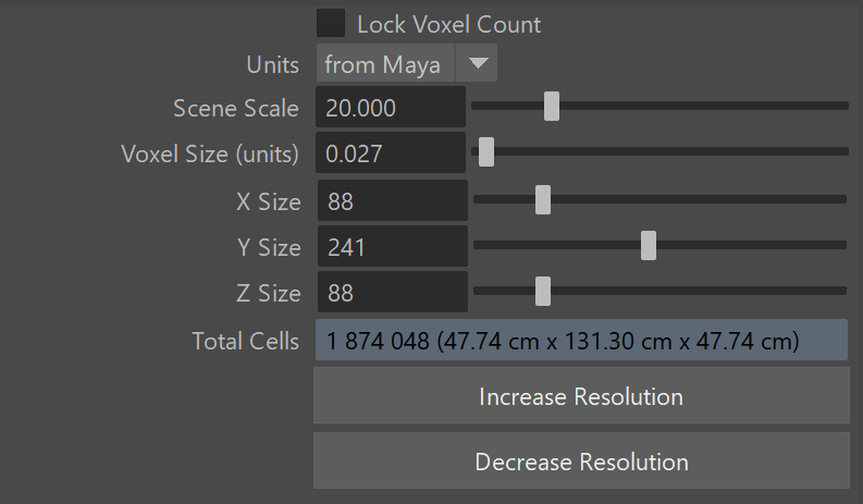
Lock Voxel Count | lockGridRes – When enabled, changing the Voxel Size will adjust the simulator size and preserve the original grid resolution. When disabled, changing the Cell Size will adjust the grid resolution and preserve the simulator size.
Units | metricUnits – Set the scale of the units used by the Phoenix simulation. By default the metric units are taken from Maya, but can be overridden to use certain units.
Scene Scale | unitsScale – Specifies a multiplier for the original units of the scene. Phoenix works best when the container size is close to the real-world size of the desired effect. You can use this parameter to make the fluid solver see the container as bigger or smaller than it actually is in the scene, in case you cannot change the general scene units of Maya. Check the sizes shown in the Total Cells field - this is the size the fluid solver will use. These sizes will change as you change the Scene Scale and should be close to the real world size of the effect you are simulating. It does not matter how you view the units - in meters, centimeters, inches, etc. For example, a candle simulation can be 20 cm tall, or 0.2 m tall - it's the same.
Larger scale would make the fluid move more slowly because it needs to travel a greater distance, while smaller scale makes the fluid move faster and more chaotic. Compared to the effect of the Time Scale option in the Dynamics rollout, Time Scale makes everything slower and things continue to work in the same way (except that more simulation steps will inevitable make the fluid dissipate some velocity and detail). Scene Scale will affect some simulation parameters like gravity, cooling, burning, surface tension, the rate of birth of splashes and mist, and make them behave like this is a much larger or smaller effect. For more information, see the Units (Scene) Scale example.
Voxel Size | cellSize – The size of a single voxel, in Units. When Lock Voxel Count is disabled, these values change the number of cells. When Lock Voxel Count is enabled, these values change the size of the grid without changing the number of cells. For more information on the impact of the Cell Size on your simulations, see the Grid Resolution example below.
X Size, Y Size, Z Size | xSize, ySize, zSize – The grid size in cells. The dimensions shown in the Total Cells info box are the grid size in the scene, multiplied by the Scene Scale parameter - these sizes show how the solver will see the grid box and you can use the Scene Scale to cheat the solver into simulating as if the grid box was larger or smaller. In case you want to see how big the container for the loaded cache is in the scene without accounting for the Scene Scale, see the Container Dimensions in the Simulation rollout. Changing one of the sizes to 1 allows the simulator to perform a 2D Simulation. For more information on how to do this, please see the Setting up a 2D Simulation example below.
Increase/Decrease resolution – Changes the resolution of the grid while maintaining its size.
Example: Scene Scale
The following video provides examples to show the differences of Scene Scale with values of 0.1, 5.0 and 15.0.
Example: Grid Resolution
The following video provides examples to show the differences when the Total cells from the Grid's Resolution is at 570,000, 4,000,000and 16,000,000.
Example: Setting up a 2D Simulation
A 2D Simulation can be performed by adjusting the Grid dimensions such that either X Size, Y Size, or Z Size is set to 1. The main application of this feature is to create very wide fires that would otherwise be time-consuming with a 3D simulation, like the image below.
To keep features like the embedded gravity and pressure decay, it is recommended to leave the Y direction active and set the X or Z size to 1.

Container Walls
X,Y,Z | gridBCX, gridBCY, gridBCZ – Select between different container wall conditions for the simulation grid.
Open – The fluid is allowed to leave the bounding box of the Simulator through this wall. When simulating Liquids, if Fill Up for Ocean is enabled, the Wall is treated as if there is infinite liquid below the Initial Fill Up level.
Jammed(-) – The simulation behaves as if there is a solid boundary in the negative direction. The Adaptive Grid will not expand in this direction.
Jammed(+) – The simulation behaves as if there is a solid boundary in the positive direction. The Adaptive Grid will not expand in this direction.
Jammed Both – The simulation behaves as if there is a solid boundary in both directions. The Adaptive Grid will not expand in this direction.
Wrap – The left and right boundaries are connected (toroidal topology). E.g. Fluid leaving the Simulator from the +X wall will enter it again from the -X wall.

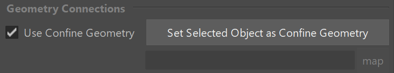
Geometry Connections
Use Confine Geometry | gridUseGizmo – When enabled, constrains the simulation only to the volume of a shape.
Set Selected Object as Confine Geometry – You can specify a closed geometry object with normals pointing outwards, and the simulation will run only inside this object. The rest of the cells will be frozen as if a solid body was covering them. This way you can fill irregular shapes with liquid, or generally speed up your simulation by chopping off empty cells when you have an irregular fluid shape, e.g. a rocket launch.
While using a Confine Geometry can speed up a simulation, it will not reduce RAM usage.
Confine Geometry | gridGizmo – Shows the currently selected Confine Geometry.
Grid Adaptation
Adaptive Grid | adaptive – Enables the adaptive grid option and determines which channel to use (see the Threshold parameter). The grid will then resize to fit the volume occupied by the selected channel. Only channel values above the Threshold will affect the adaptive grid. Note that only the Open Container Walls will expand and contract using the Adaptive Grid.
Either keep Adaptive Grid disabled or set the Container Walls: Y to Jammed Both when simulating Oceans. The Ocean Level parameter in the Rendering rollout depends on the vertical size of your simulator.
Adapt By Particles | adaptby – Specifies the particle system that will be used for the grid adaptation. More than one particle system can be used by using a comma to separate the different systems. For example Liquid, Foam will resize the grid based on the movement of both the liquid and the foam particle systems. Available systems are Liquid, Foam, Splash, Mist, Wetmap. Make sure to enable Particle Velocity from the Output" rollout for all particle systems you want to use for the adaptive grid.
Threshold | gridThreshold – When Adaptive Grid is enabled, the grid expands when the content of a cell near the borders crosses this value. On the contrary, when No Smaller Than Initial Grid is disabled, the grid will contract when there are no cells with content above this value near the borders.
The Threshold value depends on the channel used for adaptation. For Smoke, a value of 0.01 is a good starting point. For Fire, setting the Adaptive Grid Channel to Temperature/Liquid and increasing the Threshold to 800 or more should give you good results.
Extra Margin | adaptMargin – Specifies the number of cells between the end of the grid and the active zone. You can use this to give the fluid a bit more room if the adaptive grid can't keep up with the simulation.
No Smaller Than Initial Grid | nbiGrid – When enabled, the Adaptive Grid can't contract to a smaller size than what is given as the initial X,Y,Z size for the Simulator. Note that this way the initial grid box is always included, even if the fluid has moved farther from it. If this option is disabled, the grid will always encompass only the active fluid and will move together with it if needed.
Expand and Don't Shrink | onlyExpand - When enabled the Adaptive Grid will expand without shrinking. If this option is disabled, the grid may shrink if the content of the tracked channel for a given section of the simulator is below the Threshold value. This option is useful when making very thin smoke simulations which usually will contract the grid when the fluid gets below the Threshold value.
Max Memory % | adapt_maxmem_percent – If memory consumption reaches the specified percentage, the grid won't expand any further.
Preallocate Memory | gridPrellocate – When the grid size is changed, a new grid is allocated and the old content is transferred into the new space. However, during this process, both grids, the new and the old one, exist simultaneously and the RAM usage is doubled. This way you will be able to use only as much as half of your memory. To solve this problem, this option allocates all memory in the beginning of the simulation at once (eventually limited by the Max Memory and Maximum expansion), and simulates only in a part of it, allowing re-size without doubling the memory usage.
Disabled – Allocates the exact amount of memory. If the grid changes its resolution during the simulation, a new piece of memory is allocated for it, and the old one is copied over. This temporarily increases the overall consumed memory. This mode is the easiest to set up but is not recommended for huge grids.
When Adaptive – Preallocates memory when the Adaptive Grid mode is enabled. Limited By and Limited To control how much memory is preallocated at the start of the simulation. No other grid memory allocations are done during the simulation.
Always – Always preallocates memory at the start of the simulation, regardless of grid settings/resizing. Limited by and Limited To control the exact amount. This can be used if the grid is manually resized.

Manual Adaptation Limits
By default, the adaptation algorithm uses the Container Walls to determine if the grid can be extended in a particular direction. If the wall is open, this means that cells in that direction can be added. The maximum grid expansion is only limited by total cells or memory used. This section allows fine control over the grid expansion in each direction.
Enable Limits | adaptLimitEnbl – Enables using manual limits along each axis when adapting the grid.
-/+ X | adaptLimitXp, adaptLimitXn – Specifies the limits along X axis.
-/+ Y | adaptLimitYp, adaptLimitYn – Specifies the limits along Y axis.
-/+ Z | adaptLimitZp, adaptLimitZn – Specifies the limits along Z axis.
Shrink to View | adaptCamera – Species a camera whose frustum will be used to determine the maximum expansion. The Adaptive Grid will not resize beyond the frustum. Note that the algorithm might not handle complicated cases properly. For such cases, the limits must be animated manually.
Set Selected Camera - When a camera and a Phoenix Simulator are selected, the selected camera's frustum will be used to determine the maximum expansion.
When a Shrink to View Camera is provided, the Adaptive Grid will expand no further than the already specified Adaptation Limits.
