This page offers information on Camera clipping, Transformations, and Areas rollouts of Chaos Scatter in Maya.
Camera Clipping
Enable – When enabled, instances are limited to a camera view. The rest are clipped away. This option may improve scene parsing performance and lower memory requirements. It is disabled by default.
The Camera clipping tool is an optimization tool. It is not intended for limiting instances to a certain area and should not be used for that purpose. It is recommended to use other tools for limiting instance spread, such as the Areas rollout.
Clipping Camera – Determines the camera to use when clipping instances.
Current Renderable Camera – Clips the instances based on the active camera view used for rendering. The clipping is visible in the viewport only when the clipping parameters are changed or if Interactive Rendering is running. This is because, otherwise, the clipping would be too intrusive during regular scene work. With a reasonable Extended View value, this mode is recommended for optimizing your scene. It works automatically, so it automatically saves scene parsing time and RAM usage.
front, persp, side, top – Select one of these modes to use the corresponding camera from the scene for clipping. In this case, the clipping is always visible in the viewport.
Extended View – Specifies a uniform extension of the camera view in all directions, in centimeters. Adds an extra zone beyond the camera view and behind the camera, where the instances are not clipped. This is useful for ensuring correct shadows or reflections from instances that would otherwise be clipped.
The Camera Clipping tool could cause some missing shadows and/or reflections. The Extended View option can be used to amend that by allowing some extra space for those details to be included.
Enable Distance Clipping – When enabled, allows using the Near and Far Clipping Planes to control the camera clipping extension. The Near threshold value determines the minimum distance from the camera before which instances are clipped. The Far threshold distance determines the maximum distance away from the camera, after which instances are clipped. This option gives extra control over the clipping. It is disabled by default.

Transformations
Translation
Moves the instances From the given distance To the given distance on the corresponding axis (in scene units) in a randomized way. A Map 1 can be attached. RGB maps can control translations in specific axes (Red = X; Green = Z; Blue = Y). Grayscale maps control all axes proportionally. See the Translation example below for more information.
Map Mode – Determines how the map is interpreted to control the translation.
Map Fixed – Black areas of the map represent the From values. White areas of the map represent the To values. No randomization occurs.
Random Amount – Black areas of the map do not have any randomization applied. In the white areas of the map, full randomization occurs. The From and To values represent the lowest and highest translations allowed for the randomization.
Map Axes – Determines which axes the Map is applied to.
Step – Determines a fixed distance by which all instances translate. If the value is left at zero, instances are translated continuously. Values greater than the difference between To and From result in all instances translating to the value of To. See the Translation example below for more information.
Step Axes – Determines which axes the Step is applied to.
![]()
Example: Translation
This example shows how the randomized translation affects the scattered rocks with and without Step calculated.

X = 0-0; Y = 0-0; Z = 0-0

X = 0-25; Y = 0-0; Z = 0-0

X = 0-100; Y = 0-100; Z = 0-0

X = 50-100; Y = 50-100; Z = 0-0

X = 50-100; Y = 50-100; Z = 0-25

X = 50-100; Y = 50-100; Z = 0-100

X = 50-100; Y = 50-100; Z = 50-100

X = 0-100; Y = 0-100; Z = 0-0; Step = 0

X = 0-100; Y = 0-100; Z = 0-0; Step = 50
Rotation
Map Mode – Determined how the map is interpreted to control the rotation.
Map Fixed – Black areas of the map represent the From values. White areas of the map represent the To values. All values in between are on the grayscale spectrum. No randomization occurs.
Random Amount – Black areas of the map have no randomization applied. In white areas of the map, full randomization occurs. The From and To values specify the lowest and highest rotation for the randomization.
Map Axes – Determines which axes the Map is applied to.
Step – Determines a fixed degree by which all instances rotate for the enabled axes. If the value is set to 0, instances are rotated continuously. Values greater than the difference between To and From result in all instances rotating to the value of To. See the Rotation and Step example below for more information.
Step Axes – Determines which axes the Step is applied to.
Normal Alignment – When a value different than 0 is entered, the instances are aligned according to the world Y axis. A value of 0 means the objects are following the target surfaces curve, and 1 means they are fully upright along Y. This is useful when the Target object is curved, and the Model objects need to remain vertical, not follow the curve of the surface, e.g., trees on a mountain. See the Normal Alignment example below for more information.
Preserve Model Rotation – When enabled, instances preserve the original rotation of the Instanced model object. Otherwise, the original rotation is ignored. This is useful when scattering proxy files. See the Preserve Model Rotation example below for more information.
When working with Cosmos assets (proxy objects), bare in mind the default rotation of the object is -90° on the X axis.

Example: Rotation and Step
This example shows the randomized rotation of the instances within a given axis range. The last three images show the rotation with a set Step size.
Example: Normal Alignment
The trees in this example are scattered on an uneven terrain. By moving the value of the Normal Alignment parameter between 0 and 1, the trees get aligned to the normals under different angles.

X = 0-0; Y = 0-0; Z = 0-360; Step Size = 0

X = 0-0; Y = 0-0; Z = 0-360; Step Size = 30

X = 0-0; Y = 0-0; Z = 0-360; Step Size = 60

X = 0-0; Y = 0-0; Z = 0-360; Step Size = 90

X = 0-0; Y = 0-0; Z = 0-360; Step Size = 180

X = 0-0; Y = 0-0; Z = 0-360; Normal Alignment = 0

X = 0-0; Y = 0-0; Z = 0-360; Normal Alignment = 0.25

X = 0-0; Y = 0-0; Z = 0-360; Normal Alignment = 0.5

X = 0-0; Y = 0-0; Z = 0-360; Normal Alignment = 0.75

X = 0-0; Y = 0-0; Z = 0-360; Normal Alignment = 1.0
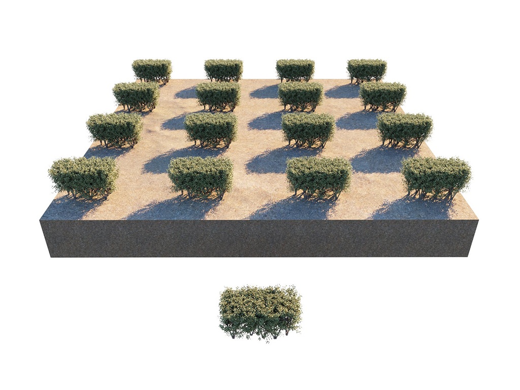
Example: Preserve Model Rotation
This example compares two cases - when the original model is rotated (at 90°) but Preserve Model Rotation is disabled, and when the original model is rotated and the Preserve Model Rotation is used.

Look At
Enable – When enabled, instances in a range get turned towards a specified direction.
Target Object – Picks an object according to which the direction aligns. When a geometry object is picked, each instance gets oriented towards the center of the object’s bounding box. When a camera object is picked, each instance orients towards the camera.
Look Axis – Selects which of the model object's axis turns towards the direction.
Reverse Orientation Axis – When enabled, the reverse of the selected axis gets turned towards the direction.
Horizontal – When enabled, the selected Look Axis turns only within the plane which is perpendicular to the normal.
Falloff Distance – Specifies the range in which instances get affected by the Look At parameters. When non-zero, only the in-range instances get affected; otherwise, all the instances get affected. There is no effect when a sun object is picked.
Falloff Curve - Sets the strength of the Look Axis option.
![]()
Example: Look At
In this example, the sunflower objects are scattered along a plane and the Look At option is enabled. The VRaySun is assigned as the Target object, and it is moved along the sky as if it was setting over the horizon. The Horizontal option is enabled, allowing the sunflowers to rotate more realistically. Slide through the images to see the movement of the sunflowers.


Scale
Scales the instances From the given value To the given value continuously with randomized results. When Uniform Scaling is enabled, the X-axis values are applied on the whole Distribute-on target object. A Map 1 can be applied. RGB maps can scale axes individually ( Red = X; Green = Z; Blue = Y). Grayscale maps control the scale of all axes proportionally. See the Scale example below for more information on the Step, Uniform Scaling, and Preserve Model Scale.
Map Mode – Determines how the map is interpreted to control the scale.
Map Fixed – Black areas of the map represent the From values. White areas of the map represent the To values. All values in between are on the grayscale spectrum. No randomization is applied.
Random Amount – Black areas of the map have no randomization applied. In white areas of the map, full randomization occurs. The From and To values represent the lowest and highest scale allowed for the randomization.
Map Axes – Determines which axes the Map is applied to.
Step – Determines a value for scaling that is applied to all instances. Values greater than the difference between To and From result in all instances scaling to the value of To.
Step Axes – Determines which axes the Step is applied to.
Uniform Scaling – When enabled, all instances in all axes are scaled according to the values of the X-axis.
Preserve Model Scale – When enabled, instances preserve the original scale of the Models object.

Example: Scale
This example shows how the instanced flower objects are scaled using Uniform Scaling and without using it. In addition, the Step and Preserve Model Scale parameters are demonstrated.

X = 1-1; Uniform Scaling = On

X = 0-2; Uniform Scaling = On

X = 1-1; Y = 1-1; Z = 1-1.5; Uniform Scaling = Off

X = 0.75-0.75; Y = 0.75-0.75; Z = 1-1.5; Uniform Scaling = Off

X = 0-1.5; Uniform Scaling = On; Step = 0

X = 0-1.5; Uniform Scaling = On; Step = 0.75

X = 1-1; Uniform Scaling = On; Preserve Model Scaling = On

X = 1-1; Uniform Scaling = On; Preserve Model Scaling = Off

X = 1-1; Uniform Scaling = On; Preserve Model Scaling = On
Areas
Include – Scatters the models only inside the curve or mesh objects included in this list. The curves cannot be the same as the Target objects. See the example below for more information.
Exclude – Scatters the models everywhere on the Target objects, except in the areas where the curves or meshes from the list are located. The curves/meshes cannot be the same as the Target objects. This option is useful, for instance, for removing instances of grass/trees from areas where a house needs to be located. See the example below for more information.
Near/Far – This option is only active when a curve or mesh from either list is selected. Determines the falloff distance from the selected curve/mesh to the selected axis plane. If the selected curve/mesh is from the Include list, instances within the falloff distance are included. If the selected curve/mesh is from the Exclude list, instances within the falloff distance are excluded. See the Falloff example below for more visual information.
If an open curve is used (start and end points are not connected), the value of the Far parameter needs to be higher than 0.
Scale – The scale factor further affects the instances between the near and the far falloff. See the Scale example below for more visual information.
Density – The density factor further affects the instances between the near and the far falloff.
Proj. Axis – Indicates on which axis the include or exclude object(s) affects the scattered model. Note that this option affects scattered models in both directions of the axis. See the Proj. Axis example below for more visual information.
See the animated example below for more information on how Areas can be used in an animation.

Example: Include and Exclude
In this example, a cylinder is used as an object in either the list of included or excluded objects.
Example: Proj. Axis
This example shows how the cylinder creates a different scatter patch on the ground depending on the alignment with the three axes.

The Object is a cylinder.

The object is in the Include list.

The object is in the Exclude list.

Axis = X

Axis = Y

Axis = Z
Example: Falloff
For this example, an include list is used. Notice how the grass spreads around the object depending on the near and far falloff.
Example: Scale
For this example, the object is in an exclude list. Depending on the scale of the falloff, the grass can be more spread out or cut off.

Falloff Near = 0; Falloff Far = 0

Falloff Near = 0; Falloff Far = 60

Falloff Near = 15; Falloff Far = 15

Falloff Near = 15; Falloff Far = 60

Falloff Near = 5; Falloff Far = 40; Scale = 1

Falloff Near = 5; Falloff Far = 40; Scale = 0.5

Falloff Near = 5; Falloff Far = 40; Scale = 0
Example: Include Curves Animation
Chaos Scatter parameters can be animated. In this example, the Include Curves list is animated. Using the Near and Far parameters, you can create effects like growing a forest.
