The Reflection rollout is part of the VRayMtl parameters.
Parameters
The BRDF parameter determines the type of the highlights and glossy reflections for the material. This parameter has an effect only if the reflection color is different from black and reflection glossiness is different from 1.0.
BRDF Type – Determines the type of BRDF (the shape of the highlight). For more information, see The BRDF Type example below.
Phong – Phong highlight/reflections. Specular highlights have a bright center with no falloff.
Blinn – Blinn highlight/reflections. Specular highlights have a bright center with a tight falloff.
Ward – Ward highlight/reflections. Specular highlights have a bright center with a falloff broader than Blinn, but tighter than Microfacet GTR (GGX).
GGX – GGX Microfacet highlight/reflections. Specular highlights have a bright center with a longer falloff.
GGX is the most modern and flexible BRDF type and is able to better represent a broad range of materials thanks to its ability to control the shape of the specular lobe.
There currently isn't any particular performance difference between models and there is little reason to choose any of the other types.
Reflection Color – Reflection color. Note that the reflection color dims the diffuse surface color. For more information, see The Reflection Color Parameter example below.
Amount – A multiplier for the reflection color.
Reflection glossiness – Controls the sharpness of reflections. A value of 1.0 means perfect mirror-like reflection; lower values produce blurry or glossy reflections. For more information, see The Reflection Glossiness Parameter example below.
Use Fresnel – When enabled, makes the reflection strength dependent on the viewing angle of the surface. Some materials in nature (glass etc) reflect light in this manner. Note that the Fresnel effect depends on the index of refraction as well.
Lock Fresnel IOR To Refraction IOR – Allows the user to unlock the Fresnel IOR parameter for finer control over the reflections.
Fresnel IOR – The IOR to use when calculating Fresnel reflections. Normally this is locked to the Refraction IOR parameter, but you can unlock it for finer control. Note that the Fresnel IOR for metals (materials with Metalness value of 1.0) does not depend on the IOR control, but is calculated from the diffuse and reflection colors. For more information, see The Use Fresnel Option example below.
GGX tail falloff – Controls the transition from highlighted areas to non-highlighted areas when the BRDF Type is set to GGX.
Metalness – Controls the reflection model of the material from dielectric (metalness 0.0) to metallic (metalness 1.0). Note that intermediate values between 0.0 and 1.0 do not correspond to any physical material. This parameter can be used with PBR setups coming from other applications. For more information, see Understanding Metalness blog post and "Artist Friendly Metallic Fresnel" article by Ole Gulbrandsen. For real-world metal examples and how to set them, see the Metal Shaders page.
Use roughness – This option controls how Reflection glossiness is interpreted. When Use roughness is selected, the Reflection glossiness inverse value is used. For example, if Reflection glossiness is set to 1.0 and Use roughness is selected, this will result in diffuse shading. Conversely, if Reflection glossiness is set to 0.0 and Use roughness is selected, this will result in sharp reflection highlights.

V-Ray Shading Model
When the Shading Model is set to OpenPBR, the material is always set to GGX, so the Brdf Type and GGX tail falloff properties are hidden. The roughness is enabled by default in this model, so the Use roughness property is also hidden.
To find out why this is, read the OpenPBR article.

OpenPBR Shading Model
Example: BRDF Type
The following examples demonstrate the different Types of BDRF.

Type: Microfacet GTR (GGX)
Modern versatile BRDF type suitable for all kinds of materials.

Type: Phong
Best used for plastic surfaces.

Type: Blinn
Multi-purpose BDRF suitable for many common materials.

Type: Ward
Useful for cloth materials and chalk-like surfaces.
Slide to change BRDF type.
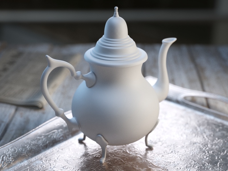
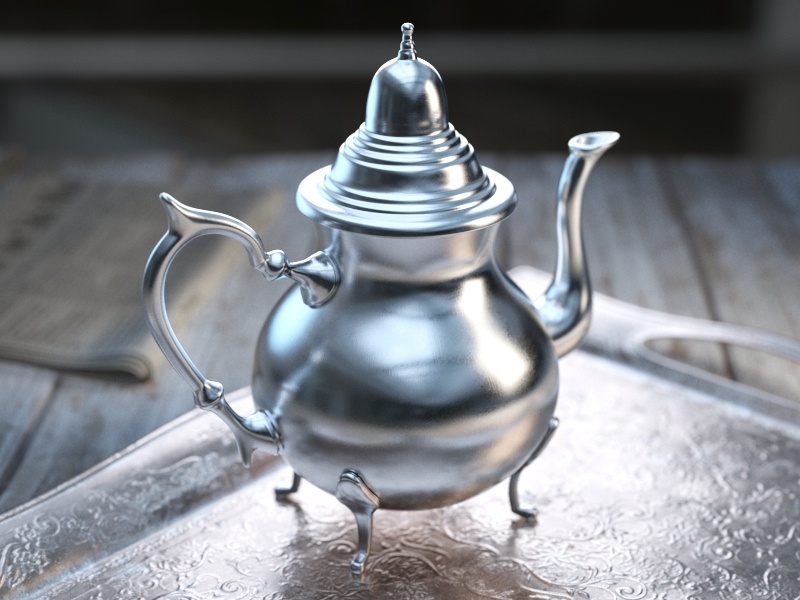
Example: Reflection Color
This example demonstrates how the Reflect color parameter controls the reflectivity of the material. Note that this color also acts as a filter for the Diffuse color (e.g. stronger reflections dim the diffuse component).
Example: Fresnel Option
This example demonstrates the effect of the Fresnel reflections option. Note how the strength of the reflection varies with the Fresnel IOR of the material. For this example, the Reflect color is pure white (255, 255, 255).

Reflect = 0, 0, 0

Reflect = 51, 51, 51

Reflect = 102, 102, 102

Reflect = 153, 153, 153

Reflect = 204, 204, 204

Reflect = 255, 255, 255

Fresnel IOR = 1.6

Fresnel IOR = 2.2

Fresnel IOR = 2.8

Fresnel IOR = 3.4

Fresnel IOR = 4.0

Fresnel IOR = 4.6

Fresnel IOR = 5.2

Fresnel IOR = 5.8

Fresnel IOR = 6.4

Fresnel IOR = 7.0

Fresnel IOR = 7.6
Example: Reflection Glossiness
This example demonstrates how the Glossiness parameter controls the highlights and reflection blurriness of the material. Fresnel IOR = 3.5.
Example: Reflection Depth
This example demonstrates the effect of the reflection Max depth parameter.

Glossiness = 0.0

Glossiness = 0.1

Glossiness = 0.2

Glossiness = 0.3
Glossiness = 0.4

Glossiness = 0.5

Glossiness = 0.6

Glossiness = 0.7

Glossiness = 0.8

Glossiness = 0.9

Glossiness = 1.0

Reflection Max Depth = 1

Reflection Max Depth = 3

Reflection Max Depth = 5

Reflection Max Depth = 8

Reflection Max Depth = 10
Anisotropy
Anisotropy – Determines the shape of the highlight. A value of 0.0 means isotropic highlights. Negative and positive values simulate "brushed" surfaces. The accepted values are in the range from 0.999 to -0.999. For more information, see The Anisotropy Parameter example below.
Anisotropy Rotation – Determines the orientation of the anisotropic effect in a float value between 0.0 and 1.0 (where 0.0 is 0 degrees and 1.0 is 360 degrees). For more information, see The Anisotropy Rotation Parameter example below.
UV Vectors Derivation – Specifies the method for deriving anisotropy axes:
Local object axis – Uses a local axis for the anisotropy effect.
Specified UVW generator – Allows the user to assign a UVW Generator for the anisotropy effect.
Local Axis – Specifies a local object axis for the anisotropy effect when UV Vectors Derivation is set to Local object axis.
Anisotropy UV Coords – Allows the user to assign a placement Texture node and change its UV coordinates to control the direction of stretching of the highlights.
To adjust the orientation of the anisotropic highlight based on the object’s local X, Y or Z create a place3dTexture node. Connect place3dTexture.worldInverseMatrix to VRayMtl.anisotropyUVWGen. Then you can rotate the place3dTexture by 90 degrees on X, Y or Z.

When the Shading Model is set to OpenPBR, the Local Axis is set to Y by default. This is due to the structure of the OpenPBR model.
Read more in the OpenPBR article and compare it to the V-Ray material structure.

Example: The Anisotropy and Rotation Parameters
This example demonstrates the effect of the Anisotropy and Rotation parameters, which determines the shape of the highlight. For the examples below the Type was set to Microfacet GTR (GGX).

Anisotropy = -0.8

Anisotropy = -0.6

Anisotropy = -0.4

Anisotropy = -0.2

Anisotropy = 0.0
Anisotropy = 0.2

Anisotropy = 0.4

Anisotropy = 0.6

Anisotropy = 0.8

Rotation = 0

Rotation = 18

Rotation = 36

Rotation = 54

Rotation = 72

Rotation = 90

Rotation = 108

Rotation = 126

Rotation = 144

Rotation = 162

Rotation = 180
Thin Film
Thin Film recreates the effect of thin film interference on a surface making the material iridescent. Some common uses are soap bubbles and reflective car paint layering.
Enable Thin Film – Enables the Thin Film effect.
Min Thickness (nm) – Determines the minimum thickness of the thin film. If no Thickness Blend is applied, only this value is used for the thickness of the thin film. See the Thickness example below for more information.
Max Thickness (nm) – Determines the maximum thickness of the thin film, when a Thickness Blend is applied.
Thickness Blend – Allows a map to be attached that blends the thickness values. If no map is applied, only the Min Thickness value is used to determine thickness.
IOR – Specifies the reflective index of the thin film. A map can be attached to this slot.

Example: Thin Film Min Thickness
This example shows how the Min Thickness parameter affects the specular properties of the V-Ray material, when no Thickness Blend is applied. The Thin Film IOR is set to 1.4.

Min Thickness = 0

Min Thickness = 300

Min Thickness = 450

Min Thickness = 600
Example: Creating iridescent materials with Thin Film layer
Watch this video to learn how you can use the new Thin Film option inside the V-Ray Material to create realistic soap bubbles, oil spills, and much more.
Reflection - advanced
Trace Reflections – Check this option to enable reflections for the material.
Max depth – The number of times a ray can be reflected. Scenes with lots of reflective and refractive surfaces may require higher values to look correct. See the Reflection Depth example above for illustration.
Dim distance On – Enables the Dim distance parameter which allows you to stop tracing reflection rays after a certain distance.
Dim distance – Specifies a distance after which the reflection rays will not be traced.
Dim fall off – A fall off radius for the dim distance.
Reflect On Back Side – When disabled, V-Ray will calculate reflections for the front side of objects only. Checking it will make V-Ray calculate the reflections for the back sides of objects too.
Affect Channels – Allows the user to specify which channels are going to be affected by the reflectivity of the material.
Color Only – The reflectivity will affect only the RGB channel of the final render.
Color+alpha – Causes the material to transmit the alpha of the reflected objects, instead of displaying an opaque alpha.
All channels – All channels and render elements will be affected by the reflectivity of the material. This option is useful to get Matte render elements (e.g. Cryptomatte, Matte ID, etc.) in the reflections.
When selecting the Affect All channels option, be aware that the information of the respective component affects all render elements, therefore the Back to Beauty composition will not match the RGB result from the renderer.
