This page provides information on the Camera tab of the V-Ray Renderer parameters.
Overview
The camera options control the way the scene geometry is projected onto the image, therefore changing how the render looks. These attributes override the following:
- The type of camera used for rendering
- Enable Depth of Field
- Enable motion blur effects for the standard cameras in Houdini
If you use the VRayPhysicalCamera in your scene, the parameters in this section of the Render Settings are ignored, except for the motion blur parameters: prepass samples and geometry samples.
When CUDA/RTX is chosen as a rendering engine, all unsupported options are disabled from the parameters.
Auto Corrections
Auto Exposure – Automatically determines an appropriate exposure value for the render. This option requires Light Cache in Single frame mode. Note that the Auto Exposure does not take into account pixels with zero Alpha value.
Auto White Balance – Automatically determines a suitable white balance value for the image. This option requires Light Cache in Single frame mode. Note that the Auto White Balance does not take into account pixels with zero Alpha value.
Disabled – No white balance is used, only color correction.
RGB
Temperature
Auto Corrections Mode – Specifies which camera and/or views to use the automatic exposure and white balance setting. This option is available only if Auto Exposure/Auto White Balance are enabled.
All Cameras – Applies Auto Exposure and Auto White Balance to all cameras, regardless of their local exposure settings.
Cameras Without Exposure – Applies Auto Exposure and Auto White Balance only to cameras with no local exposure settings.

Camera
The cameras in V-Ray generally define the rays that are cast into the scene, which essentially is how the scene is then projected onto the viewing screen. V-Ray supports several camera types described below with sample renders in the next section.
The parameters in this rollout are ignored if you are rendering using the V-Ray Physical Camera. Exception applies for the Overscan, Motion blur parameters: prepass samples and geometry samples, Auto Exposure and Auto White Balance.
Overscan Mode – Uses the Screen Window Size parameter's values on the Houdini camera. Please note that non-uniform values for the Window Size X and Y are not supported.
Outside – The image resolution is increased proportional to the Window Size parameter's value while keeping the camera field of view.
Inside – The image resolution is preserved while keeping the camera field of view.
Type – Types of cameras available in V-Ray. You may set your scene camera to be overridden by selecting one of the following: (For more information, see the Camera Types example or the Camera Types Explained example below)
Default – Allows for the current scene camera to be used (usually a pinhole camera).
Spherical – A camera with a spherically shaped lens.
Cylindrical (Point) – This camera casts all rays from the center of a cylinder. In the vertical direction, the camera acts as a pinhole camera, and in the horizontal direction, the camera acts as a spherical camera.
Cylindrical (Ortho) – This camera casts all rays are cast from the center of a cylinder. In the vertical direction, the camera acts as an orthographic view, and in the horizontal direction, the camera acts as a spherical camera.
Box – Six standard cameras placed on the sides of a box. This type of camera is excellent for generation of environment maps for cube mapping and generates a vertical cross format image. It can also be used for generating irradiance maps for GI: First you would calculate the irradiance map with a Box camera, then save it to a file and finally reuse it with a Default camera that can be pointed in any direction.
Fish-Eye – This special type of camera captures the scene as if it is a pinhole camera pointed at a 100% reflective sphere that reflects the scene back into the camera's shutter, as with using a light probe in HDRI photography. You can use the Distance and Fov settings to control which part of the sphere is captured by the camera. Note that the virtual reflective sphere has always a radius of 1.0.
Warped Spherical (Old-Style) – A spherical camera with slightly different mapping formula than the Spherical camera.
Orthogonal – An orthographic camera enabling flat, non-perspective views.
Pinhole – Overrides the scene camera to force it to be a pinhole camera.
Spherical Panorama – Spherical camera with independent horizontal and vertical FOV selection that is useful for generating latlong images for spherical VR use.
Cube 6x1 – A variant of the Box camera with the cube sides arranged in a single row. Unlike the Box camera's output, Cube 6x1 does not produce an empty space in the output image and is quite useful in generating cubic VR output.
Override Field Of View – Overrides Houdini's camera FOV (field-of-view) angle. Some V-Ray camera types can take FOV ranges from 0 to 360 degrees, whereas the cameras in Houdini are limited to 180 degrees.
Field of View – The FOV (field-of-view) value to override the Houdini camera's own FOV setting.
Auto White Balance Samples Accumulation Mode –

Example: Renders of Camera Types
The images below show the difference between the different camera types used in rendering:

Default camera

Spherical camera

Cylindrical (Point) camera

Cylindrical (Ortho) Camera

Box camera

Fish-Eye camera
Example: Camera Types Explained
This example shows how the rays for different camera types are generated. The red arcs in the diagrams correspond to the FOV angles.

Default
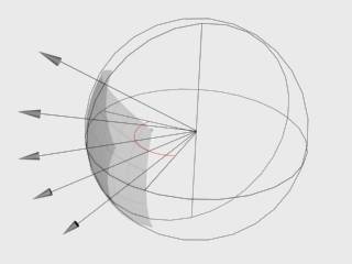 Spherical
 Cylindrical (Point)
 Cylindrical (Ortho)
 Box
Box

Fish-Eye
Depth of Field
These parameters control the depth of field (DOF) effect when rendering with a standard Houdini camera. The parameters are ignored if you render with a V-Ray Physical Camera.
Note: Depth of field is supported only for the Default camera type. Other camera types do not produce depth of field effect at this time.
Enable – Toggles on or off the Depth-of-field effect and its related parameters.
Aperture – The size of the virtual camera aperture, in world units. Small aperture sizes reduce the DOF effect.
Center Bias – Determines the uniformity of the DOF effect. A value of 0.0 means that light passes uniformly through the aperture. Positive values mean that light is concentrated towards the rim of the aperture, while negative values concentrate light at the center.
Get Focus Distance From Camera – When enabled, the Focus Distance is determined from the camera target.
Focus Distance – Determines the distance from the camera at which objects is in perfect focus. Objects closer or farther than this distance are blurred.
Anisotropy – Stretches the bokeh effect horizontally or vertically. Positive values stretch the effect in the vertical direction, while negative values stretch the effect in the horizontal direction.
Sides – Enables simulation of the polygonal shape of the aperture of real-world cameras. When disabled, the shape used in calculations is perfectly circular.
Number Of Sides – Sets the number of sides for the polygonal shape of the aperture.
Rotation – Specifies the orientation of the aperture shape.

Motion Blur Parameters
When rendering Alembic file sequences (e.g. file.$F4.abc), V-Ray expects a velocity attribute for creating the Motion Blur effect. To generate the "v" attribute prior to export, use a Trail SOP. The "Geometry Velocity Blur" option has to be set to "Velocity Blur" under the Render → Sampling tab of the Geometry node.
This limitation is not present when rendering a sequence stored in a single Alembic file (e.g. file.abc). V-Ray is able to interpolate between the neighboring geometry samples, provided that the topology/point count of the contained geometry does not change.
These parameters set values for calculations of the Motion Blur effect. For more information, see the Motion Blur example below.
Enable Motion Blur – Toggles on or off the Motion Blur effect and its related parameters.
Geometry Samples – Determines the number of geometry segments used to approximate motion blur. Objects are assumed to move linearly between geometry samples. For objects rotating at high speed, increase this parameter to get correct motion blur. Note that higher values increase memory consumption since more geometry copies are kept in memory. For more information, see the Geometry Samples example below.
Camera Motion Blur – Enables the calculation of motion blur caused by the movement of the camera.
Duration (Frames) – Specifies the duration, in frames, during which the camera shutter is open. For more information, see the Duration example below.
Interval Center – Specifies the middle of the motion blur interval with respect to the frame. A value of 0.5 means that the middle of the motion blur interval is halfway between the frames. A value of 0.0 means that the middle of the interval is at the exact frame position. For more information, see the Interval Center example below.
Bias – Controls the bias of light for the motion blur effect. A value of 0.0 means that the light passes uniformly during the whole motion blur interval. Positive values mean that light is concentrated towards the end of the interval, while negative values concentrate light towards the beginning.
Shutter Efficiency – In real world cameras, the shutter requires some time to open and close which in turn affects the way motion blur looks. This is especially true for lenses with large apertures. To simulate this effect, this parameter controls how the motion blur samples are distributed in the time interval of the shot. A value of 1.000 means that the samples are evenly distributed, as if the shutter opens and closes instantly. Lower values produce more realistic results by placing more samples toward the middle of the time interval.
Sampling Type – Specifies the type of motion blur sampling.
Normal – Motion blur is sampled normally.
Sample only shutter open – Motion blur sampling occurs when the shutter opens.
Sample only shutter middle – Motion blur sampling occurs in the middle of the duration when the shutter is open.

Example: Motion Blur
This example demonstrates the various parameters for motion blur.

Motion blur is Off

Motion blur is On
Example: Geometry Samples
The following images demonstrate the Geometry samples parameter using the scene from the Duration example. In all the following renderings, the Duration (frames) parameter is set to 2. All other parameters are the same as for the previous images. The higher the value for Geometry Samples, the more accurate the estimated object motion. However, excessive increase of this value results in long rendering times.

Geometry Samples = 2

Geometry Samples = 8
The geometry samples parameter is useful when creating motion blur for complex motions, for example fast-rotating objects. Here is an example with an accelerating airplane propeller with a blue and yellow pattern:

Geometry Samples = 2

Geometry Samples = 3

Geometry Samples = 6

Geometry Samples = 10
Example: Duration
The following scene consists of three-frame animation of a moving cube. The cube's position on each frame:
Frame 0: Left side
Frame 1: Near box
Frame 2: Right side

The following images show frame 1 rendered with different duration values:

Duration = 0.5 (frames)

Duration = 2.0 (frames)
Example: Interval Center
This example demonstrates the effect of the Interval Center parameter. The scene is a moving sphere. Here are three sequential frames without motion blur:


 Here is the middle frame, rendered with motion blur and three different values for the interval center; the motion blur duration is one frame.
 Interval Center = 0.0; the middle of the motion blur interval matches the sphere position at the second frame

Interval Center = 0.5; the middle of the interval is halfway between the second and the third frame
 Interval Center = 1.0; the middle of the interval matches the sphere position at the third frame
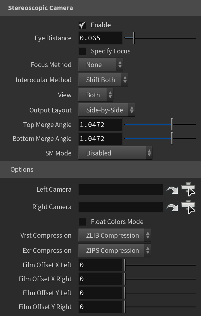
Stereoscopic Camera
Enable – Enables the Stereoscopic camera effect.
Eye Distance – Specifies the eye distance for which the stereoscopic image is rendered.
Specify Focus – When enabled, allows a point of focus to be defined.
Focus Distance – Defines the point of focus when Specify Focus is enabled.
Focus Method – Specifies the focus method for the two views. Possible values are:
None – Both cameras have their focus points directly in front of them
Rotation – Achieves the stereoscopic effect by rotating the left and right views so that their focus points coincide at the distance from the eyes where the lines of sight for each eye converge (known as fusion distance).
Shear – The orientation of both views remains the same, but each eye's view is sheared along the Z axis so that the two frustums converge at the fusion distance.
Interocular Method – Specifies how the two virtual cameras are placed in relation to the real camera in the scene.
Shift Both – Both virtual cameras are shifted in opposite directions at a distance equal to half of the eye distance.
Shift Left – The virtual cameras are shifted to the left so that the right camera takes the position of the original camera. The left camera is shifted to the left at a distance equal to the eye distance.
Shift Right – The virtual cameras are shifted to the right so that the left camera takes the position of the original camera. The right camera is shifted to the right at a distance equal to the eye distance.
View – Specifies which of the stereoscopic views are rendered.
Both – Both views are rendered side by side.
Left – Only the left view is rendered.
Right – Only the right view is rendered.
Output Layout – Specifies the format in which the Stereoscopic renders are output.
Top Merge Angle – Determines the panoramic pole merging (from what angle near the top the stereo effect starts to fade when rendering with a spherical panorama camera).
Bottom Merge Angle – Determines the panoramic pole merging (from what angle near the bottom the stereo effect starts to fade when rendering with a spherical panorama camera).
Sm Mode – Specifies the mode of operation for the shade map.
Disabled – No shade map is used during rendering.
Render shade map – A Shade Map is created and saved in the file specified in the shade map file field.
Use shade map – Uses information from the file specified in the shade map file field.
Reuse Threshold – The reuse threshold. This value affects the rendering with shade maps. Lower values make V-Ray use less of the shade map and more real shading. This slows down the whole rendering but may be required if rendering with the default value produces artifacts. When using a relatively large DOF effect, increasing this may help to speed things up.
Shademap File – Specifies the name of the file in which the shade map information is stored.
Left Camera – A camera plugin for the left eye; if not specified, the left camera is computed based on the scene camera.
Right Camera – A camera plugin for the right eye; if not specified, the right camera is computed based on the scene camera.
Float Colors Mode – If enabled, color data is stored in full 32-bit in the shade map file; otherwise it is stored as 16-bit half-float per color component (red/green/blue).
Vrst Compression – Specifies the compression type for the .vrst files. You can choose between No Compression and ZLIB Compression.
Exr Compression – Specifies the compression type for the .exr files. You can choose between No Compression, RLE Compression, and ZIPS Compression.
Film Offset X Left – Specifies the horizontal film offset for the left camera.
Film Offset X Right – Specifies the horizontal film offset for the right camera.
Film Offset Y Left – Specifies the vertical film offset for the left camera.
Film Offset Y Right – Specifies the vertical film offset for the right camera.