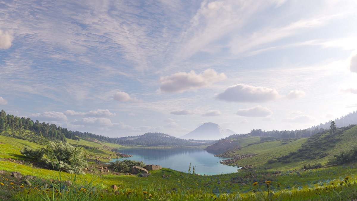
This page provides details on using the Sun system available in V-Ray for Revit.
Overview
The V-Ray Sun uses data from Revit to place the sun and render the image.
V-Ray supports all Revit sun position capabilities:
Still solar study: uses the location of the project in conjunction with the time of day/year to accurately place the sun in the sky.
Single Day: for more information, see Render Solar Study page.
Multi-Day: for more information, see Render Solar Study page.
Lighting solar study: simple azimuth and altitude settings.
More information is available on the Lighting Enhancements page of our Revit courseware.
UI Path
||Revit Ribbon|| > V-Ray tab > Lighting panel > V-Ray Sun
Parameters
Intensity – The intensity multiplier for the VRaySun. Since the sun is very bright by default, you can use this parameter to reduce its effect.
Sun Size – Controls the visible size of the sun. This affects the appearance of the sun disc as seen by the camera and reflections, as well as the blurriness of the sun shadows.
Sun Filter – Shifts the hue of the Sun Light system towards the color specified in the field.
Show Sun Disk – Controls the visibility of the sun disk.
Sky
Sky Model – Specifies the procedural model that is used to generate V-Ray Sky texture.
Preetham et al. – V-Ray Sky procedural texture is generated based on the Preetham et al. method.
CIE Clear – V-Ray Sky procedural texture is generated based on the CIE method for clear sky.
CIE Overcast – V-Ray Sky procedural texture is generated based on the CIE method for cloudy sky.
Hosek et al. – V-Ray Sky procedural texture is generated based on the Hosek et al. method.
PRG Clear Sky – V-Ray Sky procedural texture is generated based on the Improved method which has enhanced sunrise and sunset sky.
Horizontal Illum. – Specifies the intensity (in lx) of the illumination on horizontal surfaces coming from the sky.
Turbidity – Determines the amount of dust in the air and affects the color of the sun and sky. Smaller values produce a clear, blue sky and sun as seen in rural areas, while larger values make them yellow and orange as seen in big cities.
Ozone – Affects the color of the light. Values closer to 0.0 make the sunlight yellow, and values closer to 1.0 make it blue.
Ground Albedo
Albedo Color – Sets the ground color of the V-Ray Sun and Sky system.
Blend Angle – Specifies the angle in degrees where blending occurs between the horizon line and sky. Values close to 0.0 produce a sharper horizon line, while larger values produce a softer horizon line.
Horizon Line – Allows you to manually lower the horizon line.
Clouds
Enables the Cloud system.
Ground Shadows – Enables the clouds shadows, best suited for larger scenes. Note that it is recommended to use a Dome light with a Sky texture for high quality shadows. When disabled, a single shadow is cast over the entire scene depending on whether the sunlight reaching the camera position is blocked by a cloud. Disabling ground shadows is recommended for smaller scenes and may speed up the render process. See the Clouds Shadows example below.
Match with Enscape – When enabled, the Enscape cloud system position and orientation are used, so that the clouds are rendered matching in both Enscape and V-Ray. When disabled, the V-Ray cloud system position and orientation are used. More information about this option can be found in Render Enscape procedural clouds with V-Ray.
The Match with Enscape option is shown in the V-Ray Sun panel only if there is an Enscape Settings preset(s) in the project.
Density – Controls the density of the clouds. Higher values result in more clouds. See the Clouds Density example below.
Variety – Controls the clouds variety in space and shape. See the Clouds Variety example below.
Cirrus Amount – Controls the amount of high-altitude cirrus clouds. A value of 0 results in no cirrus clouds. See the Cirrus Amount example below.
Latitude – Moves the clouds left and right by latitude.
Longitude – Moves the clouds back and forth by longitude.
Height – Controls the clouds position in height. See the Clouds Height example below.
Thickness – Controls the clouds thickness. Low values result in thin and sheer/lucent clouds. Higher values result in full and heavy clouds. See the Clouds Thickness example below.
Example: Clouds Density
The Density parameter controls the amount of clouds in the sky. The higher the value, the higher the amount of clouds appearing in the render.
Example: Clouds Variety
This example shows the effect of the Variety parameter on the clouds' distribution and look.
Example: Clouds Shadows
This examples shows the effect of the Ground Shadows option.
Example: Cirrus Amount
This example shows how increasing the Cirrus Amount increases the appearance of the cirrus clouds in the render.
Example: Clouds Height
This example shows how the clouds change their position in the sky with increasing the Height value.
Example: Clouds Thickness
The Thickness parameter specifies how full the clouds are. Smaller values make them thinner and sheerer, while higher values make them look heavy.
Contrails
When enabled, plane contrails are simulated in the sky.
Number – Determines the number of contrails generated. See the Contrails Number example below.
Strength – Determines the opacity of the contrails. Lower values create less opaque trails, which look older. See the Contrails Strength example below.
Distortion – Determines the amount of distortion in the contrails. See the Contrails Distortion example below.
Offset H – Offsets the contrails horizontally. See the Contrails Offset example below.
Offset V – Offsets the contrails vertically.
Contrails Time – Determines how far the contrails progress along the sky. See the Contrails Time example below.
Example: Number of Contrails
Note that the contrails are spread randomly across the sky. In most cases, the camera does not capture all of the contrails.
Example: Contrails Strength
This example shows how the strength parameter makes the contrails more visible and prominent in the sky.
Example: Contrails Distortion
The Contrails distortion parameter is used to achieve some variety in the trace line. Move the slider to see the example renders.
Example: Contrails Offset
The Contrails offset option introduces an offset along the X or Y direction in the sky. Move the slider to see the example renders.
Example: Contrails Time
The frames in this animation show the Contrails time parameter with values ranging between 0 and 2.0, with a step of 0.2.
Dynamic Clouds
When enabled, automatically animates the clouds movement when rendering a solar study.
Wind Direction – Specifies the direction of clouds movement measured in degrees according to the horizontal plane. A value of 0 means that the clouds will move in the positive X direction. Higher values horizontally rotate the clouds movement direction clockwise.
Wind Speed – Specifies the clouds movement speed measured in meters per second.
Phase Velocity – Specifies the clouds phase change measured in percent of the cycle per second. A value of 1 means that the phase will loop to its initial state every 100 seconds. Smaller values result in slower changes and a longer phase loop.
Background
Background – You can choose between None, Custom, and Revit.
Brightness – Controls the brightness (color intensity) of the background.
Solid Color – Specifies a solid color to be used as background.
Image – Allows you to use an image file as background and makes the following parameters available:
Placement – You can choose between Spherical and Screen placement.
Rotate H and Offset V are available for the Spherical placement.
Rotate H – Specifies the rotation of the image in degrees.
Offset V – Specifies the vertical offset of the image.
Offset X, Offset Y, Scale X, and Scale Y are available for the Screen placement.
Offset X & Offset Y – Offset the image in a coordinate system manner where X is the horizontal direction and Y the vertical one .
Scale X & Scale Y – Scale the image. The lock icon locks the proportions of the image so that it is not distorted during scale.
Background Image Preview – Previews the image. The arrows at the right corner allow you to flip the image.


