This page provides information on the V-Ray Material.
Overview
VRayMtl is a very versatile material that allows for better physically correct illumination (energy distribution) in the scene, faster rendering, and more convenient reflection and refraction parameters. This material can be easily set up to simulate a huge variety of surfaces from plastics to metals to glass and more by adjusting a handful of parameters.
Furthermore, with the VRayMtl you can apply different texture maps, control the reflections and refractions, add bump and displacement maps, force direct GI calculations, and choose the BRDF for how light interacts with the surface material.

UI Path
||Material Editor window|| > Material/Map Browser > Materials > V-Ray > VRayMtl
||V-Ray Toolbar|| > V-Ray Material button
Basic Parameters Rollout
Diffuse – Specifies the diffuse color of the material. Note the actual diffuse color of the surface also depends on the Reflect and Refract colors. This parameter can be mapped with a texture in the Maps rollout. See the Energy preservation parameter below.
Roughness – Used to simulate rough surfaces or surfaces covered with dust (for example, skin, or the surface of the moon). This parameter can be mapped with a texture in the Maps rollout. For more information, see the Roughness Parameter below. This parameter is not available when the renderer is set to GPU.
Preset – A drop-down menu with preset values for commonly used materials. See the VRayMtl Presets example below for more information.
Example: Roughness
This example demonstrates the effect of the Roughness parameter. Note how, as the Roughness increases, the material appears more "flat" and dusty.

Roughness = 0.0

Roughness = 0.1

Roughness = 0.2

Roughness = 0.3

Roughness = 0.4

Roughness = 0.5
Roughness = 0.6

Roughness = 0.7

Roughness = 0.8

Roughness = 0.9

Roughness = 1.0
Example: VRayMtl Presets
Aluminium
Aluminum (Brushed)
Aluminum (Rough)
Chrome
Copper
Copper Rough
Gold
Gold (Rough)
Iron
Lead
Silver
Silver (Rough)
Diamond
Glass
Glass (Frosted)
Glass (Tinted)
Water
Chocolate
Ceramic
Plastic
Rubber
Non-realistic materials, such as Chocolate, Plastic, Ceramic, and Rubber are ‘quick’ compared to their realistic (SSS-enabled) counterparts. They can be used for generic plastic for the plastic backs of computer monitors or laptops in a meeting room, or for the car tires in a scene where the cars are somewhere in the distance, etc.
Reflection
Reflect – Specifies the amount of reflection and the reflection color. Note that the reflection color dims the diffuse surface color based on the Energy preservation mode option. This parameter can be mapped with a texture in the Maps rollout. For more information, see the Reflection Color example below.
Glossiness – Reflection glossiness. Controls the sharpness of reflections. A value of 1.0 means perfect mirror-like reflection; lower values produce blurry or glossy reflections. Use the Subdivs parameter below to control the quality of glossy reflections. This parameter can be mapped with a texture in the Maps rollout. For more information, see the Reflection Glossiness example below.
Fresnel reflections – When enabled, the reflection strength becomes dependent on the viewing angle of the surface. Some materials in nature (glass, etc.) reflect light in this manner. Note that the Fresnel effect depends on the index of refraction as well.
Fresnel IOR – Specifies the IOR to use when calculating Fresnel reflections. Normally this is locked to the Refraction IOR parameter, but it can be unlocked for finer control. This parameter can be mapped with a texture in the Maps rollout. For more information, see the Fresnel Option example below.
Metalness – Controls the reflection model of the material from dielectric (metalness 0.0) to metallic (metalness 1.0). Note that intermediate values between 0.0 and 1.0 do not correspond to any physical material. This parameter can be used with PBR setups coming from other applications. The reflection color should typically be set to white for real world materials.
Max depth – Specifies the number of times a ray can be reflected. Scenes with lots of reflective and refractive surfaces may require higher values to look right. For more information, see the Reflection Depth example below.
Reflect on back side – When enabled, reflections are computed for back-facing surfaces too. Note that this affects total internal reflections too (when refractions are computed).
Dim distance – Specifies the distance after which the reflection rays are not traced.
Dim fall off – Specifies the fall off radius for the dim distance.
Subdivs – Controls the quality of glossy reflections. Lower values render faster, but the result is noisier. Higher values take longer but produce smoother results. Note that this parameter is available for changing only when Use local subdivs is enabled in the Global DMC Settings. This parameter is not available when the renderer is set to GPU.
Affect channels – Allows the user to specify which channels are affected by the reflection of the material.
Color only – The reflection affects only the RGB channel of the final render.
Color+alpha – The material transmits the alpha of the reflected objects instead of displaying an opaque alpha.
All channels – All channels and render elements are affected by the reflections of the material.
Example: Reflection Color
This example demonstrates how the Reflect color parameter controls the reflectivity of the material. Note that this color also acts as a filter for the Diffuse color (e.g. stronger reflections dim the diffuse component).
Example: Fresnel Option
This example demonstrates the effect of the Fresnel reflections option. Note how the strength of the reflection varies with the Fresnel IOR of the material. For this example, the Reflect color is pure white (255, 255, 255).
Reflect = 0, 0, 0
Reflect = 26, 26, 26
Reflect = 51, 51, 51
Reflect = 77, 77, 77
Reflect = 102, 102, 102
Reflect = 128, 128, 128
Reflect = 153, 153, 153
Reflect = 179, 179, 179
Reflect = 204, 204, 204
Reflect = 230, 230, 230
Reflect = 255, 255, 255
Fresnel IOR = 1.6
Fresnel IOR = 2.2
Fresnel IOR = 2.8
Fresnel IOR = 3.4
Fresnel IOR = 4.0
Fresnel IOR = 4.6
Fresnel IOR = 5.2
Fresnel IOR = 5.8
Fresnel IOR = 6.4
Fresnel IOR = 7.0
Fresnel IOR = 7.6
Example: Reflection Glossiness
This example demonstrates how the Glossiness parameter controls the highlights and reflection blurriness of the material. Fresnel IOR = 3.5.
Example: Reflection Depth
This example demonstrates the effect of the reflection Max depth parameter.
Glossiness = 0.0
Glossiness = 0.1
Glossiness = 0.2
Glossiness = 0.3
Glossiness = 0.4
Glossiness = 0.5
Glossiness = 0.6
Glossiness = 0.7
Glossiness = 0.8
Glossiness = 0.9
Glossiness = 1.0

Reflection Max depth = 1

Reflection Max depth = 2

Reflection Max depth = 3

Reflection Max depth = 4

Reflection Max depth = 5

Reflection Max depth = 10
Refraction
Refract – Specifies the amount of refraction and the refraction color. Any value above zero enables refraction. Note that the actual refraction color depends on the Reflect color as well. This parameter can be mapped with a texture in the Maps rollout. For more information, see the Refraction Color example below.
Glossiness – Controls the sharpness of refractions. A value of 1.0 means perfect glass-like refraction; lower values produce blurry or glossy refractions. Use the Subdivs parameter below to control the quality of glossy refractions. This parameter can be mapped with a texture in the Maps rollout. For more information, see the Refraction Glossiness example below.
IOR – Specifies the index of refraction for the material, which describes the way light bends when crossing the material surface. A value of 1.0 means the light does not change direction. This parameter can be mapped with a texture in the Maps rollout. For more information, see the Refraction IOR example below.
Abbe number – Increases or decreases the dispersion effect. Enabling this option and lowering the value widens the dispersion and vice versa. For more information, see the Abbe Number example below.
Affect Channels – Specifies which channels are affected by the transparency of the material.
Color Only – The transparency affects only the RGB channel of the final render.
Color+alpha – The material transmits the alpha of the refracted objects instead of displaying an opaque alpha. Note that currently, this works only with clear (non-glossy) refractions.
All channels – All channels and render elements are affected by the transparency of the material.
Subdivs – Controls the quality of glossy refractions. Lower values render faster, but the result is noisier. Higher values take longer but produce smoother results. This parameter also controls the quality of the translucent effect, if on (see below). This parameter is not available when the renderer is set to GPU.
Max depth – Specifies the number of times a ray can be refracted. Scenes with lots of refractive and reflective surfaces may require higher values to look right. For more information, see the Refraction Depth example below.
Affect shadows – When enabled, this parameter causes the material to cast transparent shadows to create a simple caustic effect dependent on the refraction color and the fog color. For accurate caustic calculations, disable this parameter and instead enable Caustics in the GI tab. Simultaneous usage of both Caustics and Affects Shadows can be used for artistic purposes but do not produce a physically correct result.This only works with V-Ray shadows and lights.
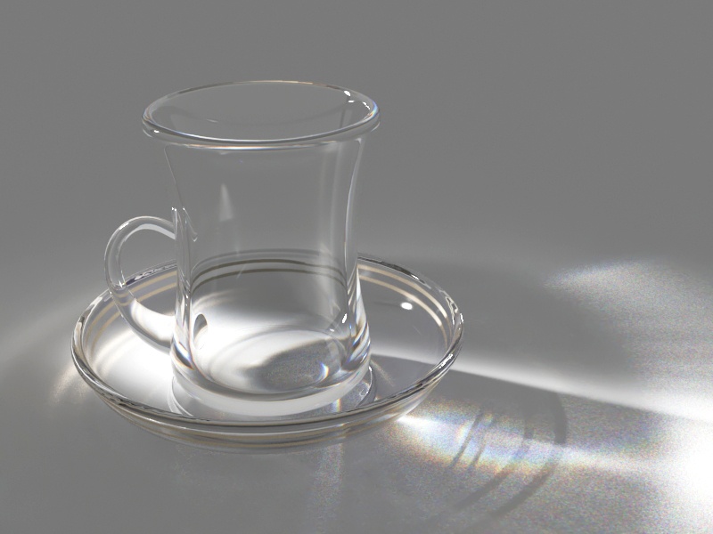
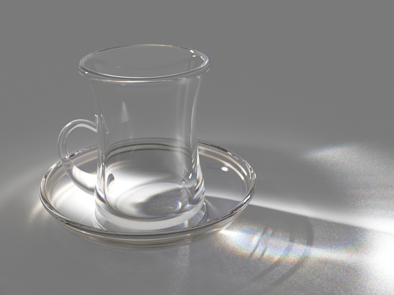
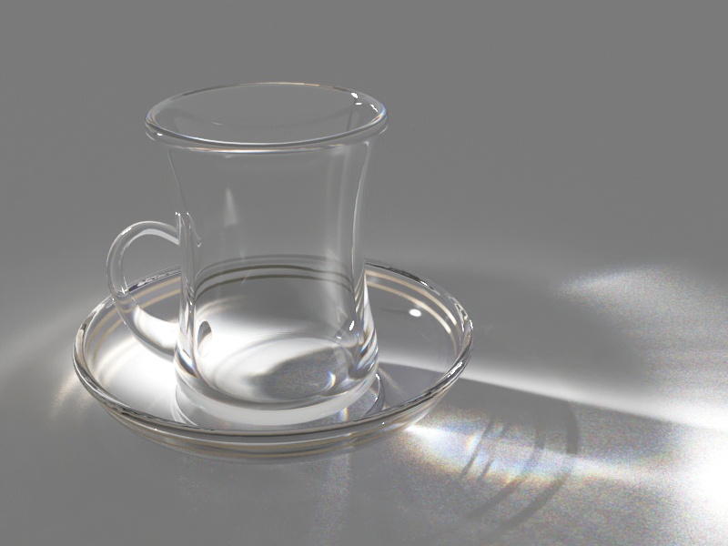
Example: Refraction Color
This example demonstrates the effect of the Refract color parameter to produce glass materials. For the images in this example, the material has a gray Diffuse color, white Reflect color, and the Fresnel Reflections option is enabled.
Example: Refraction IOR
This example demonstrates the effect of the Refraction IOR parameter. Note how light bends more as the IOR deviates from 1.0. When the index of refraction (IOR) is 1.0, the render produces a transparent object. Note, however, that in the case of transparent objects, it might be better to assign an opacity map to the material rather than use refraction.
Refraction Color = 0, 0, 0
Refraction Color = 26, 26, 26
Refraction Color = 51, 51, 51
Refraction Color = 77, 77, 77

Refraction Color = 102, 102, 102

Refraction Color = 128, 128, 128
Refraction Color = 153, 153, 153
Refraction Color = 179, 179, 179

Refraction Color = 204, 204, 204
Refraction Color = 230, 230, 230

Refraction Color = 255, 255, 255

Refraction IOR =0.80

Refraction IOR = 1.00
Refraction IOR = 1.20

Refraction IOR = 1.40

Refraction IOR = 1.60

Refraction IOR = 1.80

Refraction IOR = 2.00

Refraction IOR = 2.20
Refraction IOR = 2.40
Refraction IOR = 2.60
Refraction IOR = 2.80
Example: Refraction Glossiness
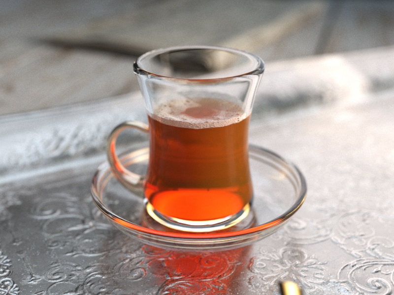
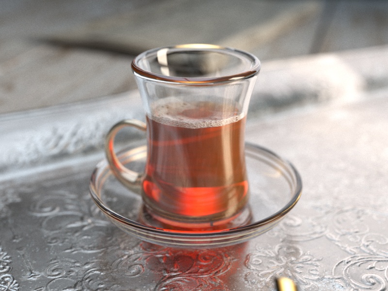
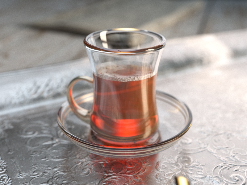
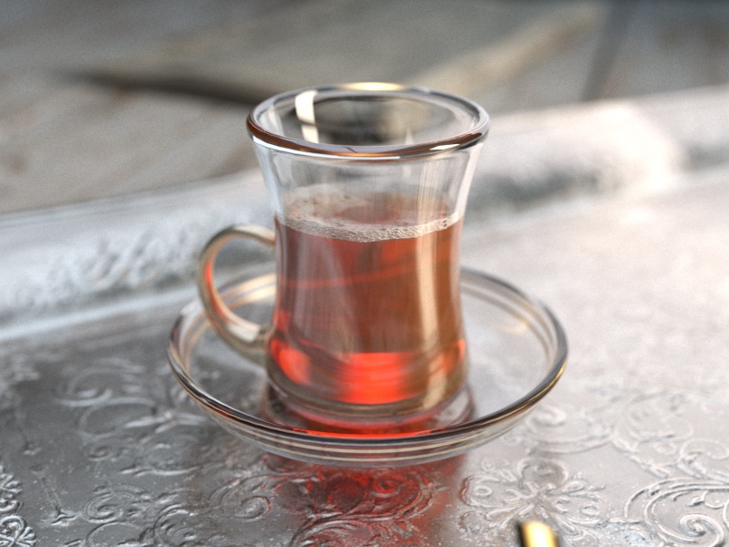
This example demonstrates the effect of the refraction Glossiness parameter. Note how lower refraction Glossiness values blur the refractions and cause the material to appear as frosted glass.
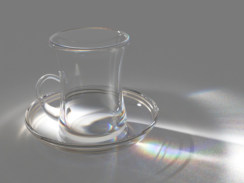
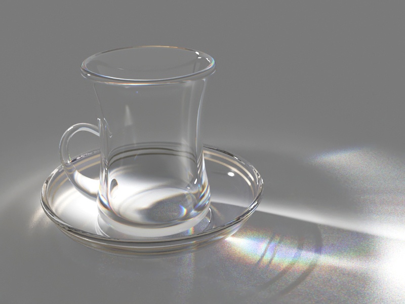
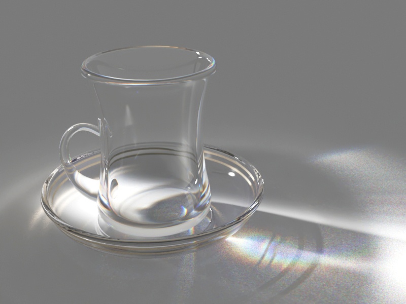
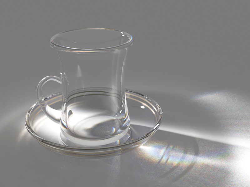
Example: Refraction Depth
This example demonstrates the effect of the refraction Max depth parameter. Note how too low of a refraction depth produces incorrect results. Also, in the last two examples, note how areas with total internal reflection are also affected by the Reflection Max depth.
Refraction Glossiness = 0.0

Refraction Glossiness = 0.1

Refraction Glossiness = 0.2

Refraction Glossiness = 0.3
Refraction Glossiness = 0.4

Refraction Glossiness = 0.5
Refraction Glossiness = 0.6

Refraction Glossiness = 0.7
Refraction Glossiness = 0.8

Refraction Glossiness = 0.9

Refraction Glossiness = 1.0
Refraction Max depth = 1

Refraction Max depth = 2

Refraction Max depth = 3

Refraction Max depth = 4

Refraction Max depth = 5
Refraction Max depth = 10
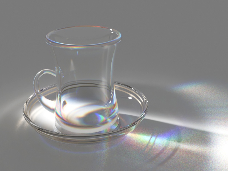
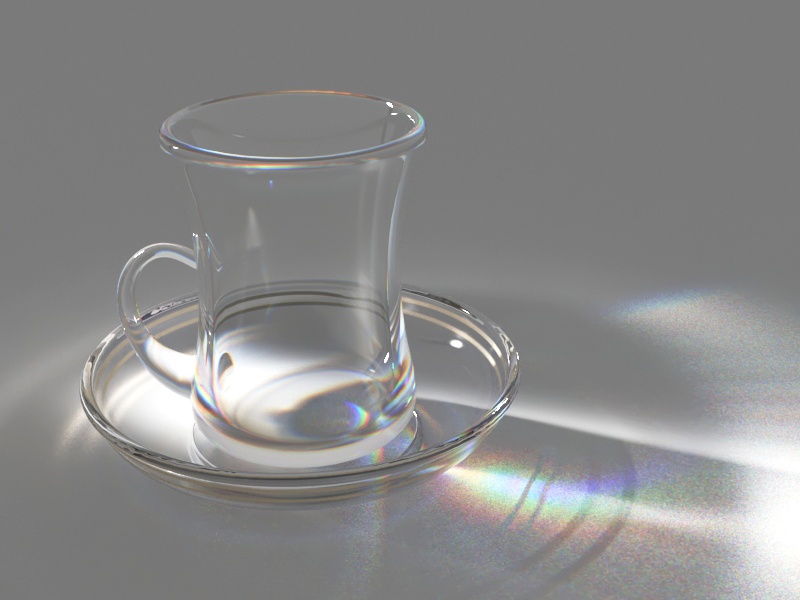
Example: Abbe Number
This example demonstrates the dispersion capabilities of the V-Ray material and the effect of the Abbe number parameter.
Abbe Number = 1
Abbe Number = 2
Abbe Number = 3
Abbe Number = 4
Abbe Number = 5

Abbe Number = 6
Abbe Number = 7
Abbe Number = 8
Abbe Number = 9
Abbe Number = 10
Fog
Fog color – Specifies the attenuation of light as it passes through the material. This option allows the user to simulate the fact that thick objects look less transparent than thin objects. Note that the effect of the fog color depends on the absolute size of the objects and is therefore scene-dependent unless the Fog system units scaling is enabled. This parameter also determines the look of the object when using translucency. This parameter can be mapped with a texture in the Maps rollout. It is recommended that you use a 3D texture for the purpose. For more information, see the Fog Color example below.
Fog multiplier – Controls the strength of the fog effect. Smaller values reduce the effect of the fog, making the material more transparent. Larger values increase the fog effect, making the material more opaque. In more precise terms, this is the inverse of the distance at which a ray inside the object is attenuated with an amount equal to the Fog color. For more information, see the Fog Multiplier example below.
Fog bias – Changes the way the fog color is applied. Negative values make the thin parts of the objects more transparent and the thicker parts more opaque and vice-versa (positive numbers make thinner parts more opaque and thicker parts more transparent).
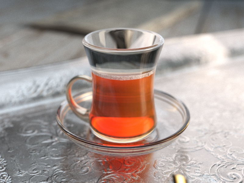
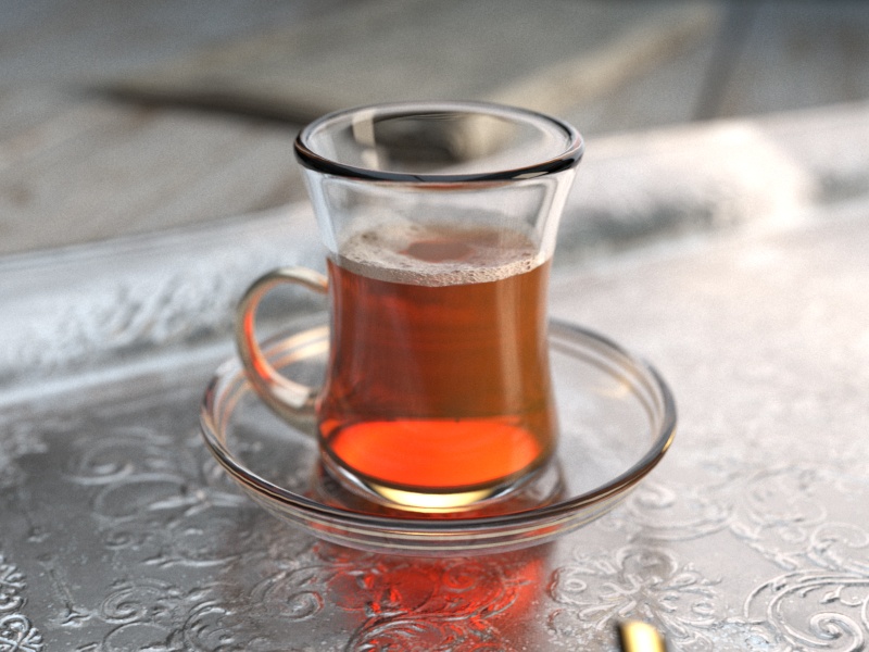
Example: Fog Color
This example demonstrates the effect of the Fog color parameter. Notice that we are changing the hue value of the Fog color.
Example: Fog Multiplier
This example demonstrates the effect of the Fog multiplier parameter. Smaller values cause less light absorption because of the fog; while higher values increase the absorption effect.
Fog color (HSV) Hue = 0
Fog color (HSV) Hue = 36
Fog color (HSV) Hue = 72
Fog color (HSV) Hue = 108
Fog color (HSV) Hue = 144
Fog color (HSV) Hue = 180
Fog color (HSV) Hue = 216
Fog color (HSV) Hue = 252
Fog color (HSV) Hue = 288
Fog color (HSV) Hue = 324
Fog color (HSV) Hue = 360
Fog multiplier = 0.3
Fog multiplier = 0.6
Fog multiplier = 0.9
Fog multiplier = 1.2
Fog multiplier = 1.5
Fog multiplier = 1.8
Fog multiplier = 2.1
Fog multiplier = 2.4
Fog multiplier = 2.7
Fog multiplier = 3.0
Fog multiplier = 3.3
Translucency
Translucency – Selects the algorithm for calculating translucency (also called sub-surface scattering). Note that refraction must be enabled for this effect to be visible. Currently, only single-bounce scattering is supported. For more information, see the Translucency example below.
None – No translucency is calculated for the material;
Hard (wax) model – This model is specifically suited for hard materials like marble;
Soft (water) model – This model is mostly for compatibility with older V-Ray versions (1.09.x);
Hybrid model – This is the most realistic sss model and is suitable for simulating skin, milk, fruit juice and other translucent materials.
Scatter coeff – Specifies the amount of scattering inside the object. A value of 0.0 means rays are scattered in all directions; A value of 1.0 means a ray cannot change its direction inside the sub-surface volume.
Fwd/bck coeff – Controls the direction of scattering for a ray. A value of 0.0 means a ray can only go forward (away from the surface, inside the object); 0.5 means that a ray has an equal chance of going forward or backward; 1.0 means a ray is scattered backward (towards the surface, to the outside of the object).
Thickness – Limits the rays that are traced below the surface. This is useful if the whole sub-surface volume does not need to be traced. For more information, see the Thickness example below.
Back-side color – Normally the color of the sub-surface scattering effect depends on the Fog color; this parameter allows you to additionally tint the SSS effect.
Light multiplier – Specifies a multiplier that controls the strength of the translucent effect.
The Translucency rollout is not available in V-Ray GPU Next.
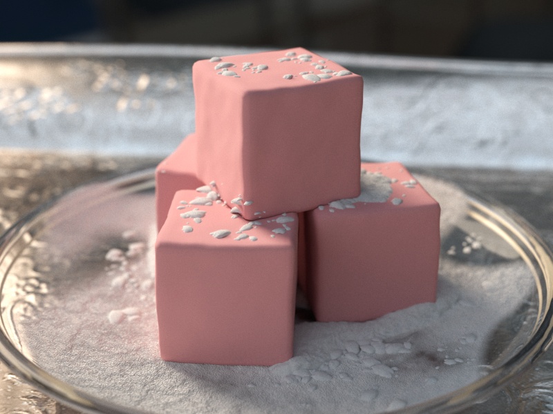
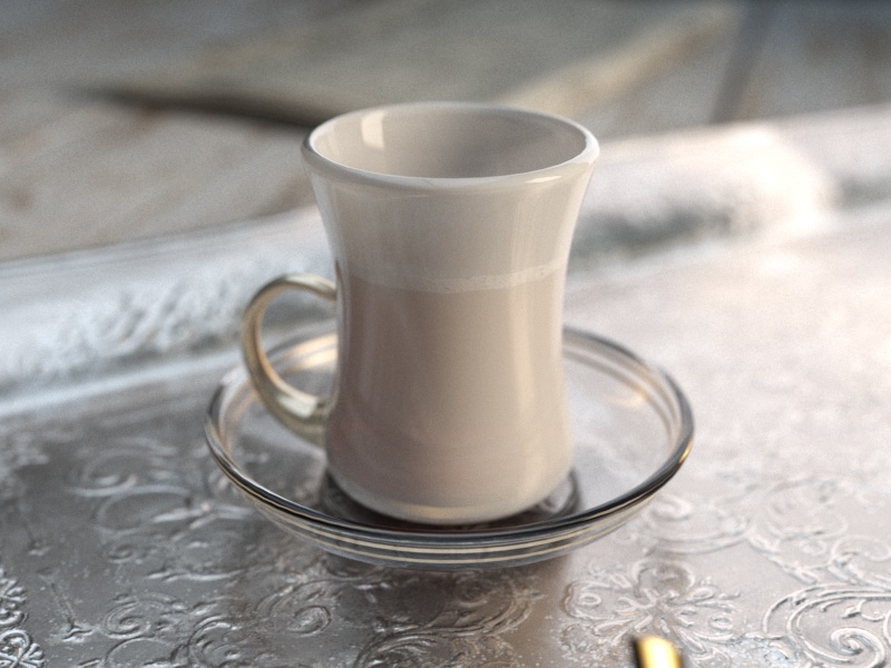
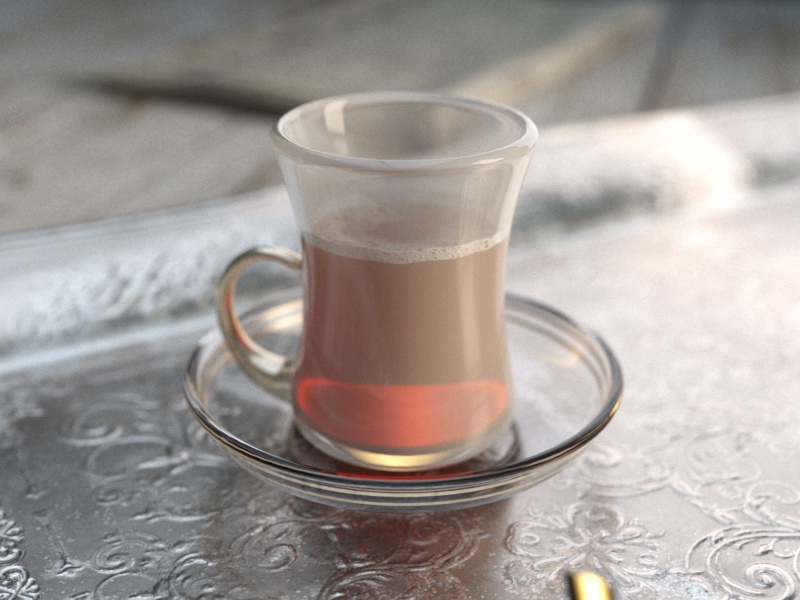
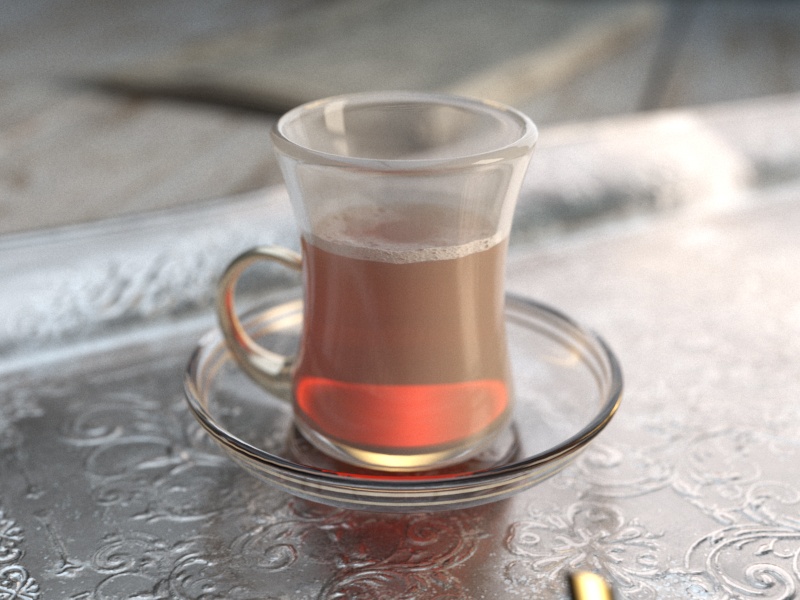
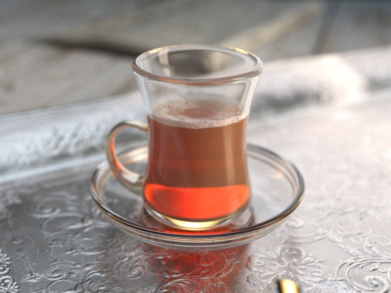
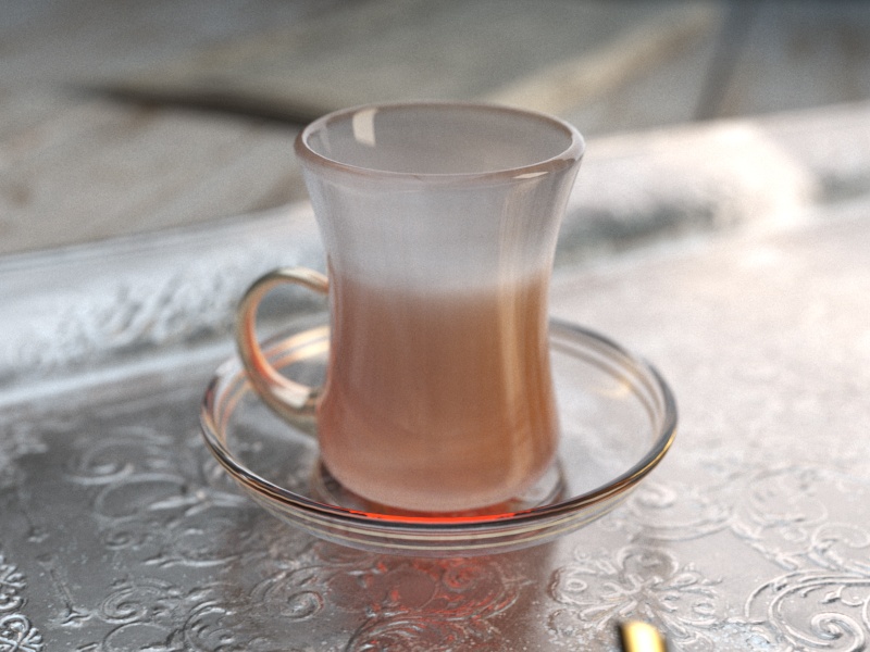
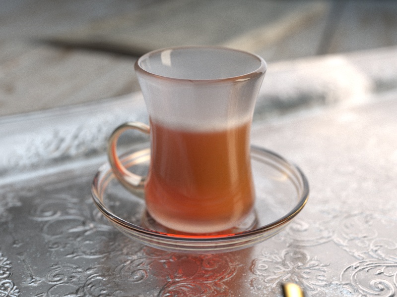
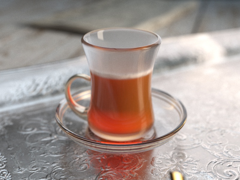
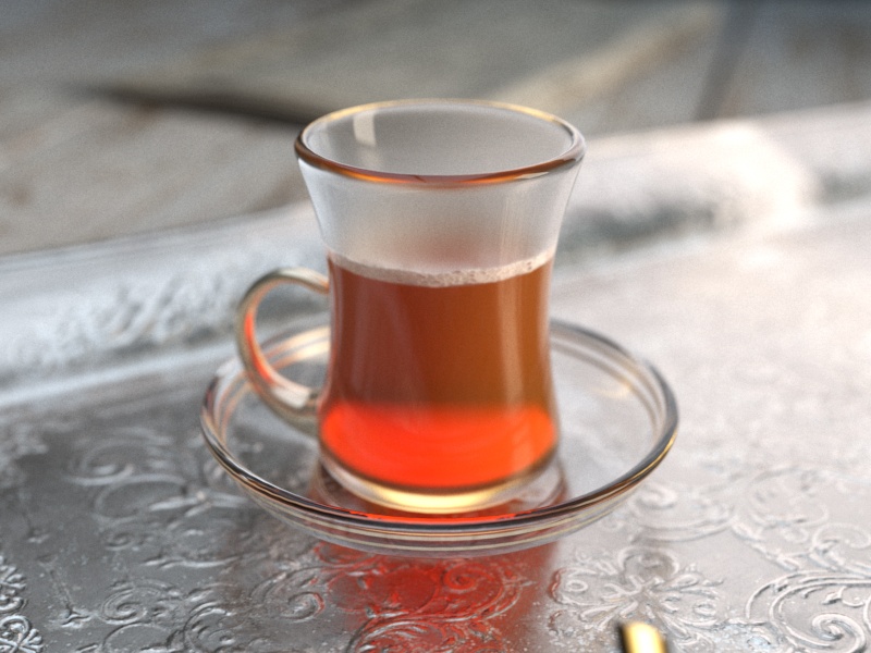
Example: Translucency
This example demonstrates the effect of the Translucency parameter. Note that refraction must be enabled for this effect to be visible. Currently, only single-bounce scattering is supported.
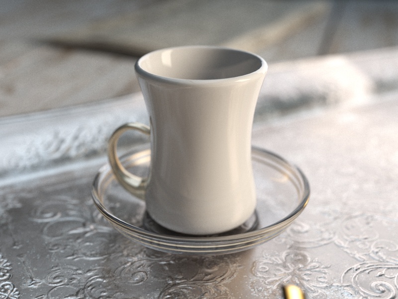
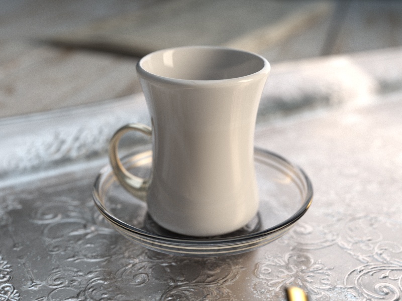
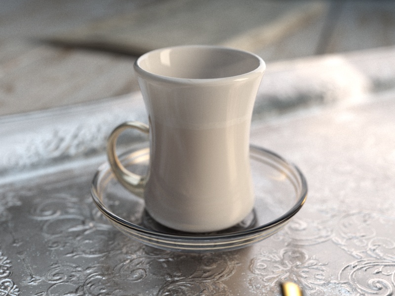
Example: Thickness
This example demonstrates the effect of the Thickness parameter which limits the rays that will be traced below the surface. This is useful if the whole sub-surface volume does not need to be traced.
Translucency = None
Translucency = Hard (wax)
Translucency = Soft (water)
Translucency = Hybrid
Slide to change the Translucency model.
Translucency thickness = 1 cm
Translucency thickness = 2 cm
Translucency thickness = 3 cm
Translucency thickness = 4 cm
Translucency thickness = 5 cm
Translucency thickness = 10 cm
Translucency thickness = 15 cm
Translucency thickness = 20 cm
Self-Illumination
Self-Illumination – Controls the emission of the surface. This parameter can be mapped with a texture in the Maps rollout.
GI – When enabled, the self-illumination affects global illumination rays and allows the surface to cast light on nearby objects. Note, however, that it may be more efficient to use area lights or VRayLightMtl material for this effect.
Mult – Specifies a multiplier for the self-illumination effect. This is useful for boosting the self-illumination values so that the surface produces stronger illumination with GI.
Compensate camera exposure – When enabled, the intensity of the Self-Illumination is adjusted to compensate the exposure correction from the physical camera.
BRDF Rollout
BRDF parameters determine the type of the highlights and glossy reflections for the material. The parameters have an effect only if the reflection color is different from black and reflection glossiness is different than 1.0.
Type – Determines the type of BRDF (the shape of the highlight). For more information, see the BRDF Type Example below.
Phong – Phong highlight/reflections. Specular highlights have a bright center with no falloff.
Blinn – Blinn highlight/reflections. Specular highlights have a bright center with a tight falloff.
Ward – Ward highlight/reflections. Specular highlights have a bright center with a falloff broader than Blinn, but tighter than Microfacet GTR (GGX).
Microfacet GTR (GGX) – GGX highlight/reflections. Specular highlights have a bright center with a longer falloff.
GGX is the most modern and flexible BRDF type and is able to better represent a broad range of materials thanks to its ability to control the shape of the specular lobe.
There currently isn't any particular performance difference between models and there is little reason to choose any of the other types.
Use glossiness / Use roughness – These options control how Reflection Glossiness is interpreted. When Use glossiness is selected, the Glossiness value is used as is, and a high Glossiness value (such as 1.0) results in sharp reflection highlights. When Use roughness is selected, the Reflection Glossiness inverse value is used. For example, if Reflection Glossiness is set to 1.0 and Use roughness is selected, this results in diffuse shading. Conversely, if Glossiness is set to 0.0 and Use roughness is selected, this results in sharp reflection highlights. Note that the Roughness parameter itself has no bearing on the results of this option.
GTR tail falloff – Controls the transition from highlighted areas to non-highlighted areas when the BRDF type is set to Microfacet GTR (GGX).
Anisotropy – Determines the shape of the highlight. A value of 0.0 means isotropic highlights. Negative and positive values simulate "brushed" surfaces. For more information, see the Anisotropy example below.
Rotation – Determines the orientation of the anisotropic effect in degrees. For more information, see the Anisotropy example below.
Local axis – When enabled, the orientation of the anisotropic highlight is based on the object's local X, Y, or Z axis.
Map channel – When enabled, the orientation of the anisotropic highlight is based on the specified map channel.
Example: BRDF Type
The following examples demonstrate the different Types of BDRF.
Type: Microfacet GTR (GGX)
Modern versatile BRDF type suitable for all kinds of materials.
Type: Phong
Best used for plastic surfaces.
Type: Blinn
Multi-purpose BDRF suitable for many common materials.
Type: Ward
Useful for cloth materials and chalk-like surfaces.
Slide to change BRDF type.
Example: Anisotropy
This example demonstrates the effect of the Anisotropy and Rotation parameters, which determines the shape of the highlight. For the examples below the Type was set to Microfacet GTR (GGX).
Anisotropy = -0.8
Anisotropy = -0.6
Anisotropy = -0.4
Anisotropy = -0.2
Anisotropy = 0.0
Anisotropy = 0.2
Anisotropy = 0.4
Anisotropy = 0.6
Anisotropy = 0.8
Rotation = 0
Rotation = 18
Rotation = 36
Rotation = 54
Rotation = 72
Rotation = 90
Rotation = 108
Rotation = 126
Rotation = 144
Rotation = 162
Rotation = 180
Options Rollout
Trace reflections – When disabled, reflections are not traced even if the reflection color is greater than black. This can be disabled to produce only highlights. Note that when disabling this parameter the diffuse color is not dimmed by the reflection color, as would happen normally.
Trace refractions – When disabled, refractions are not traced even if the refraction color is greater than black.
Cutoff – Specifies a threshold below which reflections/refractions are not traced. V-Ray tries to estimate the contribution of reflections/refractions to the image, and if it is below this threshold, these effects are not computed. Do not set this to 0.0 as it may cause excessively long render times in some cases. This parameter is not available when the renderer is set to GPU.
Env. priority – Determines the environment to use if a reflected or refracted ray goes through several materials, each of which has an environment override.
Double-sided – When enabled, V-Ray also shades the back-facing surfaces with this material. Otherwise, the lighting on the outer side of the material is always computed. This can be used to achieve a fake translucent effect for thin objects like paper.
Use irradiance map – When enabled, the irradiance map is used to approximate diffuse indirect illumination for the material. When disabled, brute force GI is used in which case the quality of the brute force GI is determined by the Subdivs parameter of the Irradiance Map. This can be used for objects in the scene which have small details and are not approximated very well by the irradiance map. This parameter is not available when the renderer is set to GPU.
Fog system units scaling – When enabled, the fog color attenuation becomes dependent on the current system units. For more information, see the Fog System Units Scaling example below.
Effect ID – When enabled, specifies input values for Material ID for the override material effect.
Glossy Fresnel – When enabled, uses glossy fresnel to interpolate glossy reflections and refractions. It takes the Fresnel equation into account for each "microfacet" of the glossy reflections, rather than just the angle between the viewing ray and the surface normal. The most apparent effect is less brightening of the grazing edges as the glossiness is decreased. With the regular Fresnel, objects with low glossiness may appear to be unnaturally bright and "glowing" at the edges. The glossy Fresnel calculations make this effect more natural.
Preserve energy – Determines how the diffuse, reflection, and refraction color affect each other. V-Ray tries to keep the total amount of light reflected off a surface to be less than or equal to the light falling on the surface (as this happens in the real life). For this purpose, the following rule is applied: the reflection level dims the diffuse and refraction levels (a pure white reflection will remove any diffuse and refraction effects), and the refraction level dims the diffuse level (a pure white refraction color will remove any diffuse effects). This parameter determines whether the dimming happens separately for the RGB components or is based on the intensity. For more information, see the Energy Preservation Mode example below.
RGB – Causes dimming to be performed separately on the RGB components. For example, a pure white diffuse color and pure red reflection color give a surface with cyan diffuse color (because the red component is already taken by the reflection).
Monochrome – Causes dimming to be performed based on the intensity of the diffuse/reflection/refraction levels.
Opacity mode – Controls how opacity is sampled. For more information, see the Opacity mode parameter example below. This parameter is not available when the renderer is set to GPU.
Normal – (Legacy) The opacity map is evaluated as normal: the surface lighting is computed and the ray is continued for the transparent effect. The opacity texture is filtered as normal.
Clip – (Very fast) The opacity texture is not filtered and it is clipped to either fully opaque or fully transparent based on the mid-point value. Useful when there are many transparent surfaces one behind the other like leaves.
Stochastic – (Optimal) The opacity texture is filtered and the surface is randomly shaded as either fully opaque or fully transparent for a correct average appearance.
Currently, setting the Opacity mode to Clip also disables bump mapping within the material. A workaround is to load the opacity map through a VRayHDRI texture map and the bump mapping will render properly.
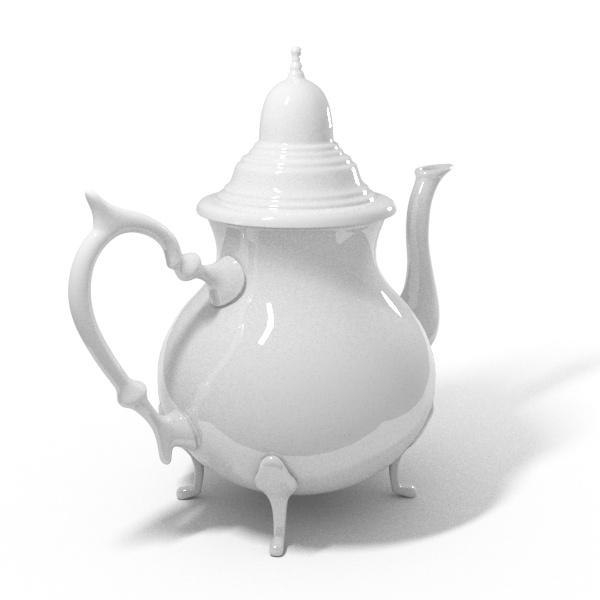
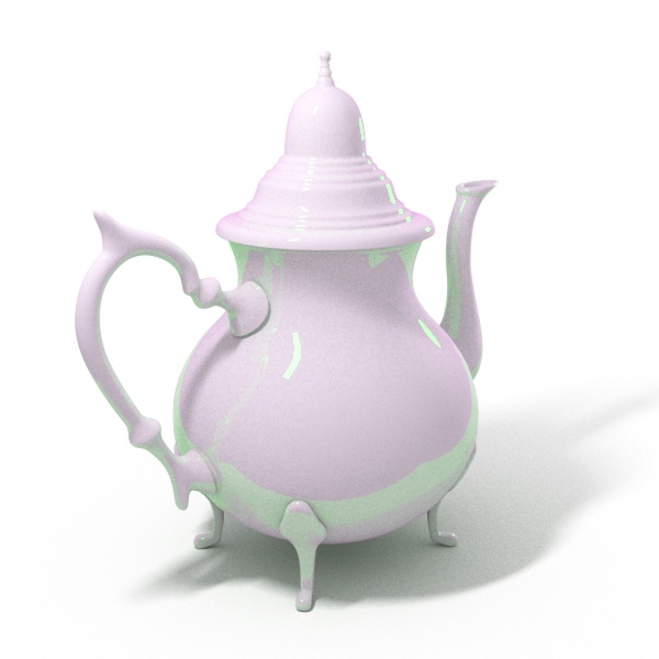
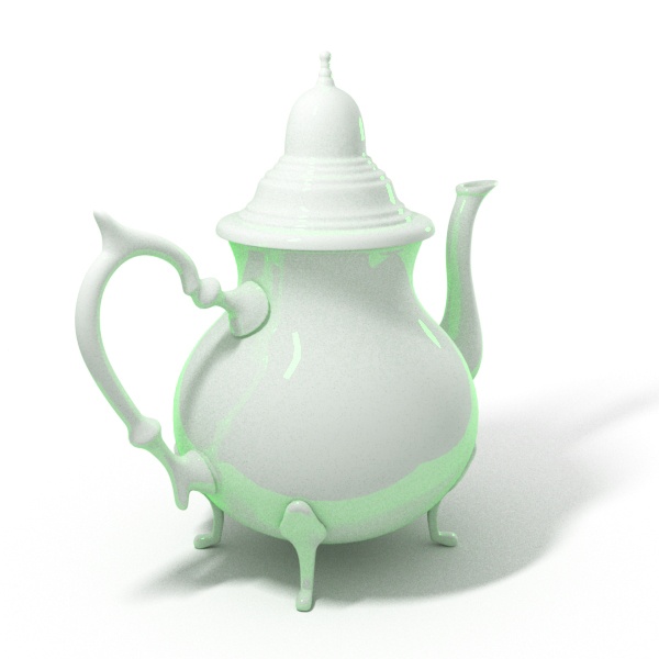
Example: Fog System Units Scaling
This example demonstrates the usage of the Fog system units scaling check box. The teapot in the scene has a radius of four meters. When the Fog system units scaling is disabled we can see through the teapot. However when we enable the Fog system units scaling, the real size of the object is taken into consideration, and we can see that the light is absorbed to a much greater extent.


Example: Energy Preservation Mode
This example demonstrates how the Energy preservation mode controls the way reflections dim the diffuse color.

Reflect = Medium Gray.
(128, 128, 128)
Reflect= Medium Green.
(0, 128, 0)
Example: Opacity mode
The renders below show a close-up of the tree to better show the effect of the different modes. Note that in the first two renders the opacity is blurry because of the texture filtering.

Opacity mode = Normal
The opacity texture is filtered and the result is nice and smooth but very slow.
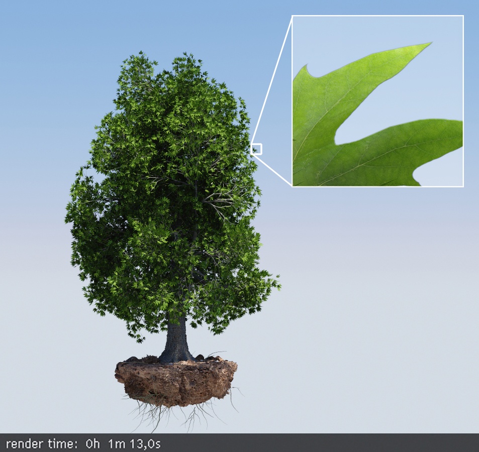
Opacity mode = Stochastic
The texture is still filtered, so the result is smooth but render times are greatly improved.

Opacity mode = Clip
The texture is forced to black or white; the render is very fast, but the result is sharper and may increase flickering in animation.
Slide to change the Opacity mode.
Maps Rollout
The settings on the Maps rollout determine the various texture maps used by the material.
Most of the parameters in this rollout pertain directly to parameters in the VRayMtl, and their definitions can be found in the Basic parameters and BRDF rollouts. The following parameters might not have such obvious definitions.
Reflect – This map slot sets the degree of reflectivity for the material. This functionality differs from the Reflection map slot for a Standard material, where a bitmap image can be set as the environment to reflect. To set an environment image to be reflected, use the Environment slot.
An. Rotation – The Rotation parameter in the BRDF rollout.
Translucent – Sets the degree of translucency when the Translucency option in the BRDF rollout is set to a selection other than None.
Environment – Specifies an environment map to use for reflections instead of the environment map for the scene. This is similar to placing a map in the Reflection slot of a Standard 3ds Max material.
Notes
Use the VRayMtl whenever possible in your scenes. This material is specifically optimized for V-Ray and often GI and lighting is computed much faster for V-Ray materials than for standard 3ds Max materials. Many V-Ray features (e.g. Light Cache, render elements ) are guaranteed to work properly only with VRayMtl and other V-Ray compliant materials.
VRayMtl can produce reflections/refractions for matte objects – see VRayMtlWrapper.
There's currently a known issue with setting the Opacity mode to Clip and bump mapping not rendering properly on a material. A workaround is to load the opacity map through a VRayHDRI texture map.
t allows you to create V-Ray Materials with preset values for commonly used situations.
Aluminum (Rough)